Instrucciones de instalación y servicio Installation and Operating instructions
|
|
|
- Εἰρήνη Γιαννόπουλος
- 8 χρόνια πριν
- Προβολές:
Transcript
1 Wilo-IL/-DL/-BL D Einbau- und Betriebsanleitung E Instrucciones de instalación y servicio GB Installation and Operating instructions I Istruzioni di montaggio, uso e manutenzione F Notice de montage et de mise en service GR Οδηγίες εγκατάστασης και λειτουργία Ed.03/ DDD

2 15 kw Fig. 1: IL Fig. 2: DL Fig. 3: BL Fig. 4

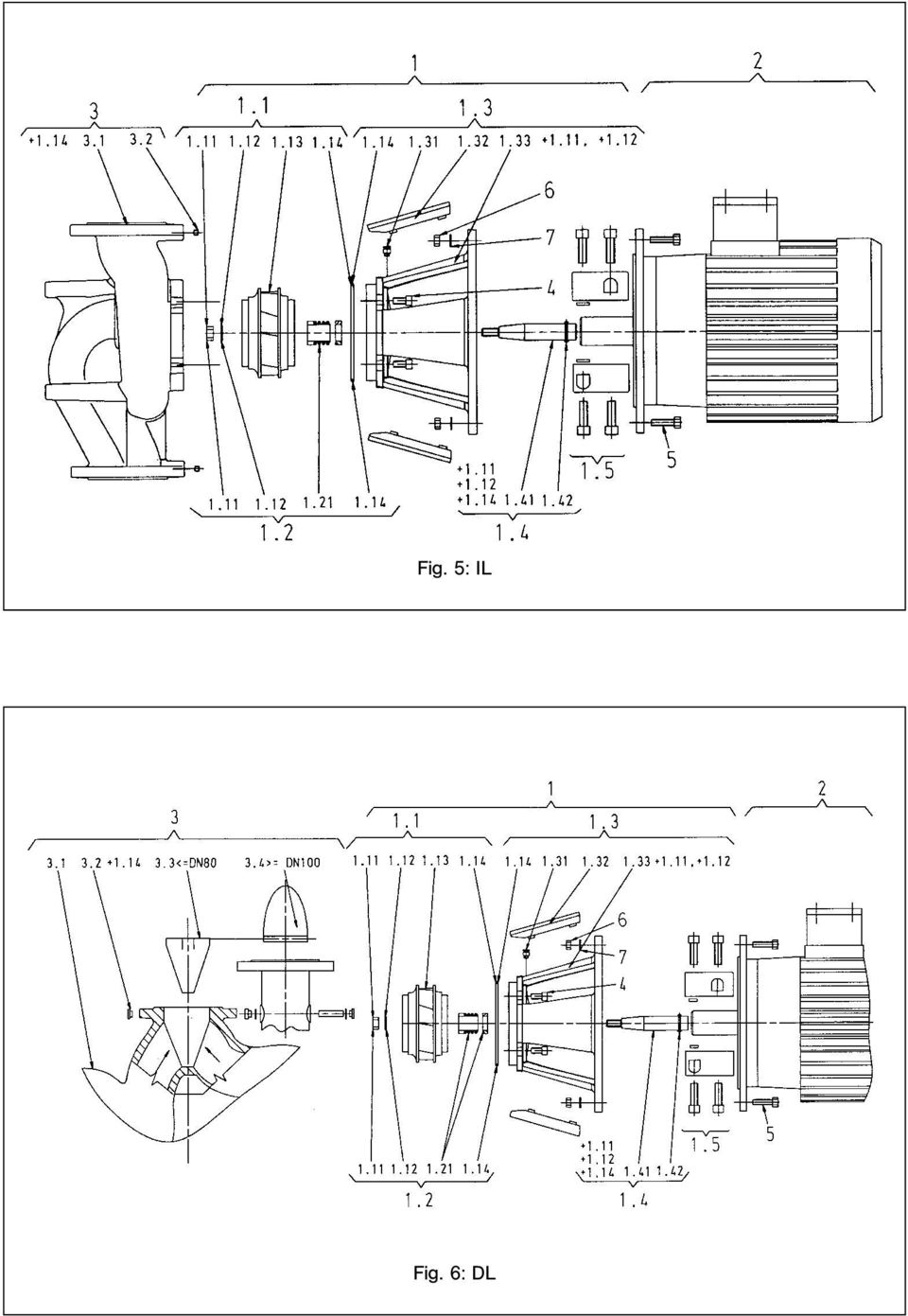
3 Fig. 5: IL Fig. 6: DL
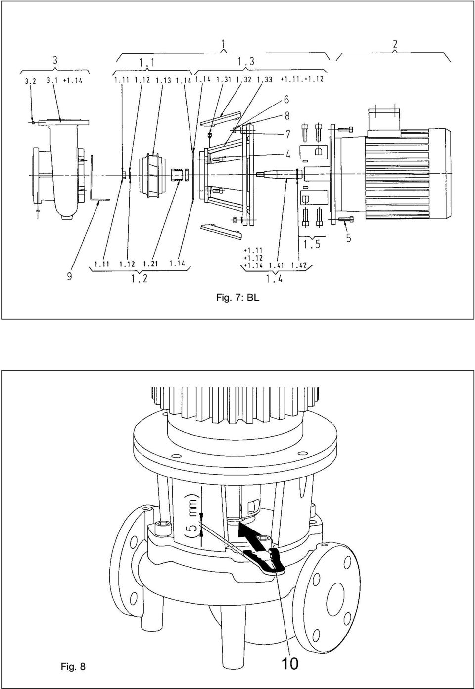
4 Fig. 8 Fig. 7: BL
5 D CE-Konformitätserklärung Allgemeines Sicherheit Transport und Zwischenlagerung Beschreibung von Erzeugnis und Zubehör 3 5. Aufstellung/Einbau Inbetriebnahme Wartung Störungen, Ursachen und Beseitigung Ersatzteile F Déclaration de conformité CE Généralités Sécurité Transport et stockage avant utilisation Description du produit et de ses accessoires Installation/Montage Mise en service Entretien Pannes, causes et remèdes rechange Pièces de rechange GB CE declaration of conformity General Safety rules Transport and intermediate storage Description of product and accessories Siting/Installation Commissioning Maintenance Faults, causes and remedies Spare parts E Declaración CE de conformidad Generalidades Seguridad Transporte y almacenaje Descripción del producto y sus accesorios Montaje/Instalación Puesta en marcha Mantenimiento Averías, causas y soluciones Repuestos I Dechiarazione CE di conformità Generalità Sicurezza Trasporto e magazzinaggio Descrizione del prodotto e accessori Montaggio/Installazione Messa in servizio Manutenzione Disfunzioni, cause e rimedi Parti di ricambio GR Πίνακας περιεχοµένων Γενικά Ασφάλεια Μεταφορά και προσωρινή αποθήκευση Περιγραφή του προϊόντος και προαιρετικά εξαρτήµατα Τοποθέτηση / Εγκατάσταση Θέση σε λειτουργία Συντήρηση Βλάβες, αίτια αποκατάσταση Ανταλλακτικά

6 DEUTSCH 1 Allgemeines Einbau und Inbetriebnahme nur durch Fachpersonal 1.1 Verwendungszweck Die Trockenläuferpumpen der Baureihen IL (Inline), DL (Doppel) und BL (Block) werden als Umwälzpumpen in der Gebäudetechnik eingesetzt in: Warmwasser-Heizungssystemen, Kühl- und Kaltwasserkreisläufen, Brauchwassersystemen, Industriellen Umwälzsystemen, Wärmeträgerkreisläufen. 1.2 Angaben über die Erzeugnisse Typenschlüssel IL 50 / 170-7,5 / 2 IL = Inline-Pumpe DL = Doppel-Pumpe BL = Block-Pumpe Nennweite des Rohranschlusses (bei BL: Druckseite) [mm] Nenndurchmesser des Laufrades [mm] Nennleistung des Motors in kw 2-poliger Motor Anschluß- und Leistungsdaten Drehzahlen: IL, DL, BL 2900, /min Nennweiten DN: IL DL BL (Druckseite) Zulässige Temperatur min./max. 20 C bis C Höchstzul. Umgebungstemp. 40 C Max. zulässiger Betriebsdruck Isolationsklasse 16 bar F Schutzart IP 55 Rohr- und Druckmessanschlüsse Flansche PN 16 nach DIN EN mit Druckmessanschlüsssen Rp 1 /8 nach DIN 3858 Zulässige Fördermedien Heizungswasser gem. VDI 2035 x Brauchwasser x Kühl-/Kaltwasser x Wasser/Glykol-Gemisch bis 40% Vol.-Anteil Glykol x Wärmeträgeröl X Andere Medien auf Anfrage X Elektrischer Anschluß 3 ~ 400 V, 50 Hz x 3 ~ 230 V, 50 Hz, bis 3 kw einschl. Y 3 ~ 230 V, 50 Hz, ab 4 kw X 3 ~ 415 /440 /500 V, 50 /60 Hz X Kaltleiterfühler X Drehzahlumschaltung, Drehzahl- Pol-Umschaltung X regelung Regelgeräte (Wilo-CR-System) x Motor-Sonderausführung Sonderspannung/-frequenz X (auf Anfrage) Explosionsschutz (EEx e, EEx de) X x Standardausführung X Sonderausführung bzw. Zusatzausrüstung (gegen Mehrpreis) Y Alternativanwendung der Standardausführung (ohne Mehrpreis) 1

7 DEUTSCH Bei Ersatzteilbestellungen sind sämtliche Daten des Pumpen- und Motortypenschildes anzugeben. Fördermedien: Werden Wasser/Glykol-Gemische im Mischungsverhältnis bis 40 % Glykolanteil (oder Fördermedien mit anderer Viskosität als reines Wasser) eingesetzt, so sind die Förderdaten der Pumpe entsprechend der höheren Viskosität, abhängig vom prozentualen Mischungsverhältnis und von der Mediumstemperatur zu korrigieren. Zusätzlich ist die Motorleistung bei Bedarf anzupassen. Nur Markenware mit Korrosionsschutz-Inhibitoren verwenden, Herstellerangaben beachten. Das Fördermedium muß sedimentfrei sein. 2 Sicherheit Diese Betriebsanleitung enthält grundlegende Hinweise, die bei Aufstellung und Betrieb zu beachten sind. Daher ist diese Betriebsanleitung unbedingt vor Montage und Inbetriebnahme vom Monteur sowie dem zuständigen Betreiber zu lesen. Es sind nicht nur die unter diesem Hauptpunkt Sicherheit aufgeführten allgemeinen Sicherheitshinweise zu beachten, sondern auch die unter den folgenden Hauptpunkten eingefügten, speziellen Sicherheitshinweise. 2.1 Kennzeichnung von Hinweisen in der Betriebsanleitung Die in dieser Betriebsanleitung enthaltenen Sicherheitshinweise, die bei Nichtbeachtung Gefährdungen für Personen hervorrufen können, sind mit dem allgemeinen Gefahrensymbol bei Warnung vor elektrischer Spannung mit besonders gekennzeichnet. Bei Sicherheitshinweisen, deren Nichtbeachtung Gefahren für die Pumpe/Anlage und deren Funktion hervorrufen können, ist das Wort ACHTUNG! eingefügt. 2.2 Personalqualifikation Das Personal für die Montage muß die entsprechende Qualifikation für diese Arbeiten aufweisen. 2.3 Gefahren bei Nichtbeachtung der Sicherheitshinweise Die Nichtbeachtung der Sicherheitshinweise kann eine Gefährdung für Personen und Pumpe/Anlage zur Folge haben. Die Nichtbeachtung der Sicherheitshinweise kann zum Verlust jeglicher Schadenersatzansprüche führen. Im einzelnen kann Nichtbeachtung beispielsweise folgende Gefährdungen nach sich ziehen: Versagen wichtiger Funktionen der Pumpe/Anlage, Gefährdungen von Personen durch elektrische und mechanische Einwirkungen. 2.4 Sicherheitshinweise für den Betreiber Die bestehenden Vorschriften zur Unfallverhütung sind zu beachten. Gefährdungen durch elektrische Energie sind auszuschließen. Vorschriften des VDE und der örtlichen Energieversorgungsunternehmen beachten. 2.5 Sicherheitshinweise für Inspektions- und Montagearbeiten Der Betreiber hat dafür zu sorgen, daß alle Inspektions- und Montagearbeiten von autorisiertem und qualifiziertem Fachpersonal ausgeführt werden, das sich durch eingehendes Studium der Betriebsanleitung ausreichend informiert hat. Grundsätzlich dürfen Arbeiten an der Pumpe/ Anlage nur im Stillstand durchgeführt werden. 2.6 Eigenmächtiger Umbau und Ersatzteilherstellung Veränderungen der Pumpe/Anlage sind nur nach Absprache mit dem Hersteller zulässig. Originalersatzteile dienen der Sicherheit. Die Verwendung anderer Teile hebt die Haftung für die daraus entstehenden Folgen auf. 2.7 Unzulässige Betriebsweisen Die Betriebssicherheit der gelieferten Anlage ist nur bei bestimmungsmäßiger Verwendung entsprechend Abschnitt 1 der Betriebsanleitung gewährleistet. Die im Katalog/Datenblatt angegebenen Grenzwerte dürfen auf keinen Fall über- bzw. unterschritten werden. 3 Transport und Zwischenlagerung ACHTUNG! Die Pumpe ist bei Transport und Zwischenlagerung gegen Feuchtigkeit und mechanische Beschädigung zu schützen. 2

8 DEUTSCH Der Transport der Pumpe ist mittels zugelassener Lastaufnahmemittel durchzuführen. Sie sind an den Pumpenflanschen und gegebenenfalls am Motor-Außendurchmesser (Sicherung gegen Abrutschen erforderlich!) anzuschlagen. Die Transportösen am Motor dienen dabei nur zur Führung bei Lastaufnahme. Die Transportösen am Motor sind nur zum Transport des Motors, nicht aber der ganzen Pumpe zugelassen. 4 Beschreibung von Erzeugnis und Zubehör 4.1 Beschreibung der Pumpen Alle hier beschriebenen Pumpen sind einstufige Niederdruck-Kreiselpumpen in Kompaktbauweise mit angekuppeltem Motor. Die Gleitringdichtung ist wartungsfrei. Die Pumpen können sowohl als Rohreinbaupumpe direkt in eine ausreichend verankerte Rohrleitung montiert oder auf einen Fundamentsockel gestellt werden. In Verbindung mit einem Regelgerät (Wilo-CR- System) kann die Leistung der Pumpen stufenlos geregelt werden. Dies ermöglicht eine optimale Anpassung der Pumpenleistung an den Bedarf des Systems und einen wirtschaftlichen Pumpenbetrieb. IL: Das Pumpengehäuse ist in INLINE-Bauart ausgeführt, d. h. saug- und druckseitige Flansche liegen in einer Mittellinie (Bild 1). Alle Pumpengehäuse sind mit Pumpenfüßen versehen. Die Montage auf einen Fundamentsockel wird ab Motornennleistung 5,5 kw und größer empfohlen. DL: Zwei Pumpen sind in einem gemeinsamen Gehäuse angeordnet (Doppelpumpe). Das Pumpengehäuse ist in INLINE-Bauart ausgeführt (Bild 2). Alle Pumpengehäuse sind mit Pumpenfüßen versehen. Die Montage auf einen Fundamentsockel wird ab Motornennleistung 4 kw und größer empfohlen. In Verbindung mit einem Regelgerät wird nur die Grundlastpumpe im Regelbetrieb gefahren. Für den Vollastbetrieb steht die zweite Pumpe als Spitzenlastaggregat zur Verfügung. Außerdem kann die zweite Pumpe die Reservefunktion im Störfall übernehmen. BL: Spiralgehäusepumpe mit Flanschabmessungen nach DIN EN 733 (Bild 3). Pumpe mit angeschraubten Standsockel bis Motorleistung 4 kw. Ab Motorleistung 5,5 kw Motoren mit angegossenen bzw. angeschraubten Füßen. 4.2 Lieferumfang IL: Inline-Pumpe Einbau- und Betriebsanleitung DL: Doppelpumpe Einbau- und Betriebsanleitung BL: Block-Pumpe Einbau- und Betriebsanleitung 4.3 Zubehör Zubehör muß gesondert bestellt werden Kaltleiterauslösegerät für Schaltschrankeinbau IL und DL: 3 Konsolen mit Befestigungsmaterial für Fundamentaufbau DL: Blindflansch für Reparatureinsätze 3

9 DEUTSCH 4.4 Geräuscherwartungswerte als Orientierung 1 ) Räumlicher Mittelwert von Motorleistung Schall-Druckpegel pa [db] 1 ) Schalldruckpegeln auf einer quaderförmigen Meßfläche in 1 m Abstand von der PN Pumpe mit Motor Motoroberfläche. [kw] 1450 min min Zulässige Kräfte und Momente an den Pumpenflanschen (nur BL-Pumpen) Pumpe Saugflansch Druckflansch Kräfte [kn] Momente [knm] BL DN [mm] DN [mm] F Vmax F Hmax M tmax 40 / ,4 1,7 0,55 40 / ,4 1,7 0,52 40 / ,4 1,7 0,50 40 / ,5 1,8 0,62 50 / ,4 1,7 0,55 50 / ,4 1,7 0,52 50 / ,4 1,7 0,50 50 / ,5 1,8 0,62 65 / ,6 1,8 0,7 65 / ,6 1,8 0,7 65 / ,6 1,8 0,7 65 / ,6 1,8 0,7 65 / ,6 1,8 0,7 80 / ,3 2,4 1,1 80 / ,3 2,4 1,1 80 / ,3 2,4 1,1 80 / ,3 2,4 1,1 4 < 0, , , , , , , ,
![Pumpe mit Motor Motoroberfläche. [kw] 1450 min -1 2900 min -1 4.](/docs-images/46/11253499/images/page_9.jpg "5 Zulässige Kräfte und Momente an den Pumpenflanschen (nur BL-Pumpen) Pumpe Saugflansch Druckflansch Kräfte [kn] Momente [knm] BL DN [mm] DN [mm] F Vmax F Hmax M tmax 40 /... 65 40 2,4 1,7 0,55 40 /.")
10 DEUTSCH Folgende Bedingung muß erfüllt sein: (F V ) (F Vmax ) 2 + (F H ) (F Hmax ) 2 + (M t ) (M tmax ) 2 1 (F V ), (F H ) und (M t ) sind die Summen der absoluten Beträge der entsprechenden an den Stutzen angreifenden Lasten. Bei diesen Summen wird weder die Richtung der Lasten noch ihre Aufteilung auf die Stutzen berücksichtigt. 5 Aufstellung/Einbau 5.1 Montage Einbau erst nach Abschluß aller Schweiß- und Lötarbeiten und der ggf. erforderlichen Spülung des Rohrsystems vornehmen. Schmutz kann die Pumpe funktionsunfähig machen. Die Standardpumpen müssen witterungsgeschützt in einer frost/staubfreien, gut belüfteten und nicht explosionsgefährdeten Umgebung installiert werden. Die Pumpe an gut zugänglicher Stelle montieren, so daß eine spätere Überprüfung oder ein Austausch leicht möglich ist. Senkrecht über der Pumpe ist ein Haken oder eine Öse mit entsprechender Tragfähigkeit (Gesamtgewicht der Pumpe: siehe Katalog/ Datenblatt) anzubringen, woran bei Wartung oder Reparatur der Pumpe Hebezeug oder ähnliche Hilfsmittel angeschlagen werden können. Die Pumpe ist mittels zugelassener Lastaufnahmemittel zu heben (siehe Absatz 3). Axialer Mindestabstand zwischen einer Wand und der Lüfterhaube des Motors: Freies Ausbaumaß von min. 200 mm + l der Lüfterhaube. Absperreinrichtungen sind grundsätzlich vor und hinter der Pumpe einzubauen, um bei Überprüfung oder Austausch der Pumpe ein Entleeren der gesamten Anlage zu vermeiden. Rohrleitungen und Pumpe spannungsfrei montieren. Die Rohrleitungen sind so zu befestigen, daß die Pumpe nicht das Gewicht der Rohre trägt. Entlüftungsventil (Bild 5, 6, 7, Pos. 1.31) muß immer nach oben zeigen Bei Einsatz der Pumpe in Klima- oder Kälteanlagen kann das in der Laterne anfallende Kondensat gezielt über vorhandene Bohrungen abgeführt werden. Jede Einbaulage außer Motor nach unten ist zulässig. Die Einbaulage mit waagerechter Motorwelle ist bei den Baureihen IL und DL nur bis zu einer Motorleistung von 15 kw zulässig. Eine Motorabstützung ist nicht erforderlich. Bei einer Motorleistung > 15 kw ist nur die Einbaulage mit senkrechter Motorwelle vorzusehen. Blockpumpen der Baureihe BL sind auf ausreichenden Fundamenten bzw. Konsolen aufzustellen. Einbaulagen: IL siehe Bild 1 DL siehe Bild 2 BL siehe Bild 3 Der Motorklemmenkasten darf nicht nach unten zeigen. Im Bedarfsfall kann der Motor bzw. Einstecksatz nach Lösen der Sechskantschrauben gedreht werden. ACHTUNG! ACHTUNG! ACHTUNG! Beim Verdrehen die Gehäuse-O- Ringdichtung nicht beschädigen. Beim Fördern aus einem Behälter ist für ein stets ausreichendes Flüssigkeitsniveau über dem Saugstutzen der Pumpe zu sorgen, damit die Pumpe keinesfalls trocken läuft. Der Mindest-Zulaufdruck muß eingehalten werden. Bei Anlagen, die isoliert werden, darf nur das Pumpengehäuse einisoliert werden, nicht Laterne und Motor (Bild 5, 6, 7, Pos. 1.3 bis 2). 5.2 Elektrischer Anschluß Der elektrische Anschluß ist von einem beim örtlichen EVU zugelassenen Elektroinstallateur und entsprechend den geltenden VDE-Vorschriften auszuführen. Der elektrische Anschluß muß nach VDE 0730/Teil 1 über eine feste Anschlußleitung erfolgen, die mit einer Steckvorrichtung oder einem allpoligen Schalter mit mindestens 3 mm Kontaktöffnungsweite versehen ist. 5

11 DEUTSCH Um den Tropfwasserschutz und die Zugentlastung der PG-Verschraubung sicherzustellen, ist eine Anschlußleitung mit ausreichendem Außendurchmesser zu verwenden. Es ist durch entsprechende Positionierung der PG-Verschraubung oder durch entsprechende Kabelverlegung sicherzustellen, daß kein Tropfwasser in den Klemmenkasten laufen kann. Bei Einsatz der Pumpen in Anlagen mit Wassertemperaturen über 90 C muß eine entsprechend wärmebeständige Anschlußleitung verwendet werden. Die Anschlußleitung ist so zu verlegen, daß in keinem Fall die Rohrleitung und/oder das Pumpen- und Motorgehäuse berührt werden. Stromart und Spannung des Netzanschlusses überprüfen. Typenschilddaten des Motors beachten. Netzseitige Absicherung: abhängig vom Motornennstrom. Erdung beachten. Das Anschlußschema für den Elektroanschluß befindet sich im Klemmenkastendeckel (s. auch Bild 4). Der Motor muß gegen Überlast durch einen Motorschutzschalter oder durch das Kaltleiterauslösegerät abgesichert werden. 6 Inbetriebnahme Pumpe, Saug- und Zulaufleitung müssen gefüllt und entlüftet sein. ACHTUNG! Die Pumpe darf nicht trocken laufen. Trockenlauf zerstört die Gleitringdichtung! Um Kavitationsgeräusche und -schäden zu vermeiden, muß ein Mindest-Zulaufdruck am Saugstutzen der Pumpe gewährleistet werden. Dieser Mindest-Zulaufdruck ist abhängig von der Betriebssituation und dem Betriebspunkt der 6 Einstellung des Motorschutzschalters: Direktanlauf: Einstellung auf Motornennstrom nach Angaben des Motortypenschildes, Y-V-Anlauf: Ist der Motorschutzschalter in die Zuleitung zur Y-V-Schützkombination geschaltet, so erfolgt die Einstellung wie bei Direktanlauf. Ist der Motorschutzschalter in einen Strang der Motorzuleitung (U1/V1/W1 oder U2/V2/W2) geschaltet, so ist der Motorschutzschalter auf den Wert 0,58 x Motornennstrom einzustellen. In Sonderausführung ist der Motor mit Kaltleiterfühlern ausgestattet. Kaltleiterfühler am Kaltleiterauslösegerät anschließen. ACHTUNG! An die Klemmen Kaltleiterfühler darf nur eine max. Spannung von 7,5V angelegt werden, höhere Spannung zerstört die Kaltleiterfühler. Der Netzanschluß an das Klemmenbrett ist abhängig von der Motorleistung P2, von der Netzspannung und von der Einschaltart. Die erforderliche Schaltung der Verbindungsbrücken imklemmenkasten ist folgender Tabelle und Bild 4 zu entnehmen: Motorleistung Motorleistung Einschaltart P2 3 kw P2 4 kw Netzspannung Netzspannung 3 ~ 230 V 3 ~ 400 V 3 ~ 400 V Direkt V-Schaltung (4a) Y-Schaltung (4b) V-Schaltung (4a) Y-V-Anlauf Verbindungsbrücken nicht möglich Verbindungsbrücken entfernen (4c) entfernen (4c) Bei Anschluß von automatisch arbeitenden Schaltgeräten die entsprechende Einbau- und Betriebsanleitung beachten. Pumpe und muß dementsprechend festgelegt werden. Wesentliche Parameter zur Festlegung des Mindest-Zulaufdruckes sind der NPSH-Wert der Pumpe in ihrem Betriebspunkt und der Dampfdruck des Fördermediums. Pumpen durch Lösen der Entlüftungsschrauben (Bild 5, 6, 7, Pos. 1.31) entlüften. Je nach Temperatur des Fördermediums und Systemdruck kann beim vollständigen Öffnen der Entlüftungsschraube heißes Fördermedium in

12 DEUTSCH flüssigem oder dampfförmigem Zustand austreten bzw. unter hohem Druck herausschießen. Es besteht Verbrühungsgefahr! Durch kurzzeitiges Einschalten überprüfen, ob die Drehrichtung mit dem Pfeil auf dem Motor übereinstimmt. Bei falscher Drehrichtung ist wie folgt zu verfahren: Bei direktem Anlauf: 2 Phasen am Klemmenbrett des Motors vertauschen (z.b. L1 gegen L2), Bei Y-V-Anlauf: Am Klemmenbrett des Motors von 2 Wicklungen jeweils Wicklungsanfang und Wicklungsende vertauschen (z.b. V1 gegen V2 und W1 gegen W2). 7 Wartung Vor Wartung- oder Instandsetzungsarbeiten Anlage spannungsfrei schalten und gegen unbefugtes Wiedereinschalten sichern. Bei hohen Wassertemperaturen und Systemdrücken Pumpe vorher abkühlen lassen. Verbrühungsgefahr! 7.1 Gleitringdichtung Die Gleitringdichtung ist wartungsfrei. Während der Einlaufzeit können geringfügige Tropfleckagen auftreten. Es ist jedoch von Zeit zu Zeit eine Sichtkontrolle erforderlich. Bei deutlich erkennbarer Leckage ist ein Dichtungswechsel vorzunehmen. Wilo bietet ein Reparatur-Set an, das die für einen Wechsel notwendigen Teile enthält. Wechsel der Gleitringdichtung (Bild 5, 6, 7): Anlage spannungsfrei schalten und gegen unbefugtes Wiedereinschalten sichern. Absperrarmaturen vor und hinter der Pumpe schließen. Pumpe durch Öffnen der Entlüftungsschraube (Pos. 1.31) drucklos machen. Bei heißen Fördermedien Verbrühungsgefahr! Motor abklemmen, falls Kabel für die Demontage des Motors zu kurz ist. Kupplungsschutz (Pos ) demontieren. Kupplungsschrauben der Kupplungseinheit (Pos. 1.5) lockern. Motorbefestigungsschrauben (Pos. 5) am Motorflansch lösen und Motor mit geeignetem Hebezeug von der Pumpe abheben. Bei BL-Pumpen löst sich der Adapterring (Bild 7, Pos. 8) mit. Durch Lösen der Laternenbefestigungsschrauben (Pos. 4), Laterneneinheit mit Kupplung, Welle, Gleitringdichtung und Laufrad vom Pumpengehäuse demontieren. Laufradbefestigungsmutter (Pos. 1.11) lösen, darunterliegende Unterlegscheibe (Pos. 1.12) abnehmen und Laufrad (Pos. 1.13) von Pumpenwelle abziehen. Gleitringdichtung (Pos. 1.21) von der Welle abziehen. Kupplung (Pos. 1.5) mit Pumpenwelle aus Laterne ziehen. Paß-/Sitzflächen der Welle sorgfältig säubern. Falls die Welle beschädigt ist, muß auch diese gewechselt werden. Gegenring der Gleitringdichtung mit Dichtmanschette aus dem Laternenflansch sowie den O-Ring (Pos. 1.14) entfernen und die Dichtungssitze säubern. Neuen Gegenring der Gleitringdichtung mit Dichtmanschette in den Dichtungssitz des Laternenflansches eindrücken. Als Schmiermittel kann handelsübliches Geschirrspül-mittel verwendet werden. Neuen O-Ring in die Nut des O-Ringsitzes der Laterne montieren. Kupplungspassflächen kontrollieren, ggf. reinigen und leicht ölen. Kupplungsschalen mit zwischengelegten Distanzscheiben auf der Pumpenwelle vormontieren und die vormontierte Kupplungs-Wellen- Einheit vorsichtig in Laterne einführen. Neue Gleitringdichtung auf die Welle ziehen. Als Schmiermittel kann handelsübliches Geschirrspülmittel verwendet werden. Laufrad mit Unterlegscheibe und Mutter montieren, dabei am Laufradaußendurchmesser kontern. Beschädigungen der Gleitringdichtung durch Verkanten vermeiden. ACHTUNG! Vorgeschriebenes Schraubenanzugsmoment beachten (siehe 7.3) Vormontierte Laterneneinheit vorsichtig in das Pumpengehäuse einführen und verschrauben. Dabei die rotierenden Teile an der Kupplung festhalten, um Beschädigungen der Gleitringdichtung zu vermeiden. ACHTUNG! Vorgeschriebenes Schraubenanzugsmoment beachten (siehe 7.3) Kupplungsschrauben leicht lösen, vormontierte Kupplung leicht öffnen. Motor mit geeignetem Hebezeug montieren und die Verbindung Laterne-Motor (und Adapterring bei BL-Pumpen) verschrauben. 7
, Bei Y-V-Anlauf: Am Klemmenbrett des Motors von 2 Wicklungen jeweils Wicklungsanfang und Wicklungsende vertauschen (z.b. V1 gegen V2 und W1 gegen W2).")
13 DEUTSCH ACHTUNG! Vorgeschriebenes Schraubenanzugsmoment beachten (siehe 7.3) Montagegabel (Bild 8, Pos. 10) zwischen Laterne und Kupplung schieben. Die Montagegabel muß spielfrei sitzen. Kupplungsschrauben zuerst leicht anziehen, bis die Kupplungshalbschalen an den Distanzscheiben anliegen. Anschließend Kupplung gleichmäßig verschrauben. Dabei wird der vorgeschriebene Abstand zwischen Laterne und Kupplung von 5mm über die Montagegabel automatisch eingestellt. ACHTUNG! Vorgeschriebenes Schraubenanzugsmoment beachten (siehe 7.3) Montagegabel demontieren. Kupplungsschutz montieren. Motorkabel anklemmen. 7.2 Motor Die Motorlager sind wartungsfrei. Erhöhte Lagergeräusche und ungewöhnliche Vibrationen zeigen einen Lagerverschleiß an. Das Lager bzw. der Motor muß dann gewechselt werden. Wechsel des Motors (Bild 5, 6, 7): Anlage spannungsfrei schalten und gegen unbefugtes Wiedereinschalten sichern. Absperrarmaturen vor und hinter der Pumpe schließen. Pumpe durch öffnen der Entlüftungsschraube (Pos. 1.31) drucklos machen. Bei heißen Fördermedien Verbrühungsgefahr! Motoranschlussleitungen entfernen. Kupplungsschutz (Pos ) demontieren. Kupplung (Pos. 1.5) demontieren. Motorbefestigungsschrauben (Pos. 5) am Motorflansch lösen und Motor mit geeignetem Hebezeug von der Pumpe abheben. Bei BL-Pumpen löst sich der Adapterring (Bild 7, Pos. 8) mit. Neuen Motor mit geeignetem Hebezeug montieren und die Verbindung Laterne-Motor (und Adapterring bei BL-Pumpen) verschrauben. ACHTUNG! Vorgeschriebenes Schraubenanzugsmoment beachten (siehe 7.3) Kupplungspassflächen und Wellenpassflächen kontrollieren, ggf. reinigen und leicht ölen. Kupplungsschalen mit zwischengelegten Distanzscheiben auf den Wellen vormontieren. Montagegabel (Bild 8, Pos. 10) zwischen Laterne und Kupplung schieben. Die Montagegabel muß spielfrei sitzen. Kupplungsschrauben zuerst leicht anziehen, bis die Kupplungshalbschalen an den Distanzscheiben anliegen. Anschließend Kupplung gleichmäßig verschrauben. Dabei wird der vorgeschriebene Abstand zwischen Laterne und Kupplung von 5mm über die Montagegabel automatisch eingestellt. ACHTUNG! Vorgeschriebenes Schraubenanzugsmoment beachten (siehe 7.3) Montagegabel demontieren. Kupplungsschutz montieren. Motorkabel anklemmen. 7.3 Schraubenanzugsmomente 8 Schraubenverbindung Anzugsdrehmoment Nm ± 10% Montageanweisungen M10 30 Laufrad-Welle M12 60 M Pumpengehäuse-Laterne M gleichmäßig über Kreuz anziehen M10 35 Laterne-Motor M12 60 M Kupplung M Paßflächen leicht ölen, M Schrauben gleichmäßig M anziehen, M Spalte beidseitig gleich halten. M
 Montagegabel demontieren. Kupplungsschutz montieren. Motorkabel anklemmen. 7.2 Motor Die Motorlager sind wartungsfrei.")
14 DEUTSCH 8 Störungen, Ursachen und Beseitigung Störung Mögliche Ursache Behebung Pumpe läuft nicht an Pumpe blockiert Motor spannungsfrei schalten, Ursache der oder setzt aus Blockierung entfernen; falls Motor blockiert, Motor / Stecksatz überholen / tauschen Kabelklemme lose Sicherungen defekt Motor schadhaft Motorschutzschalter hat ausgelöst Motorschutzschalter falsch eingestellt Motorschutzschalter durch zu hohe Umgebungstemperatur beeinflußt Kaltleiterauslösegerät hat ausgelöst alle Klemmenschrauben anziehen Sicherungen prüfen, defekte Sicherungen auswechseln Kundendienst einschalten Pumpe druckseitig auf Nennvolumenstrom eindrosseln Motorschutzschalter auf den richtigen Nennstrom des Typenschildes einstellen. Motorschutzschalter versetzen oder durch Wärmeisolierung schützen Motor und Lüfterhaube auf Verunreinigungen prüfen und ggfs. säubern, Umgebungstemperatur prüfen und ggfs. durch Zwangsbelüftung Umgebungstemperatur 40 C sicherstellen Pumpe läuft mit Falsche Drehrichtung Drehrichtung prüfen, evtl. ändern verringerter Leistung Druckseitiges Absperr- Absperrventil langsam öffnen ventil gedrosselt Drehzahl zu gering falsche Klemmenbrückung (Y anstatt V) beheben Luft in Saugleitung Undichtheiten an Flanschen beheben, entlüften Pumpe macht Unzureichender Vordruck erhöhen, Mindestdruck am Saugstutzen Geräusche Vordruck beachten, saugseitigen Schieber und Filter überprüfen und ggfs. reinigen Motor hat Pumpe durch WILO-Kundendienst oder Lagerschaden Fachbetrieb überprüfen und ggfs. instandsetzen lassen Laufrad schleift an Planflächen und Zentrierungen zwischen Laterne und Motor sowie zwischen Laterne und Pumpengehäuse überprüfen und ggfs. säubern. Kupplungspassflächen und Wellenpassflächen kontrollieren, ggfs. säubern und leicht ölen. Läßt sich die Betriebsstörung nicht beheben, wenden Sie sich bitte an Ihren Sanitär- und Heizungsfachhandwerker oder an den Wilo-Kundendienst. 9

15 DEUTSCH 9 Ersatzteile Lieferbare Ersatzteile (siehe Bild 5, 6, 7): 1 Austauschsatz komplett 1.1 Bausatz Laufrad mit 1.11 Mutter 1.12 Unterlegscheibe 1.13 Laufrad 1.14 O-Ring 1.2 Bausatz Gleitringdichtung mit 1.11 Mutter 1.12 Unterlegscheibe 1.14 O-Ring 1.21 Gleitringdichtung kpl. 1.3 Bausatz Laterne mit 1.11 Mutter 1.12 Unterlegscheibe 1.14 O-Ring 1.31 Entlüftungsschraube 1.32 Kupplungsschutz 1.33 Laterne 1.4 Bausatz Welle mit 1.11 Mutter 1.12 Unterlegscheibe 1.14 O-Ring 1.41 Welle 1.42 Sprengring 1.5 Kupplung komplett 2 Motor 3 Pumpengehäuse komplett mit 1.14 O-Ring 3.1 Pumpengehäuse (IL, DL, BL) 3.2 Stopfen für Druckmessanschlüsse 3.3 Umschaltklappe DN 80 (nur DL-Pumpen) 3.4 Umschaltklappe DN 100 (nur DL-Pumpen) 4 Befestigungsschrauben für Laterne / Pumpengehäuse 5 Befestigungsschrauben für Motor/Laterne 6 Mutter für Motor / Laterne -Befestigung 7 Unterlegscheiben für Motor/Laterne- Befestigung 8 Adapterring (nur BL-Pumpen) 9 Pumpenstützfuß für Motorgröße 4kW (nur BL-Pumpen) 10 Bild 8: Montagegabel (einzeln lieferbar) ACHTUNG! Bei allen Montagearbeiten ist, zum Einstellen der korrekten Laufradposition im Pumpengehäuse, die Montagegabel (Bild 8, Pos 10) dringend erforderlich! Eine einwandfreie Funktion der Pumpe kann nur gewährleistet werden, wenn Wilo-Originalersatzteile verwendet werden. Bei Ersatzteilbestellungen bitte o.g. Ersatzteilnummern und -bezeichnungen sowie sämtliche Daten des Pumpen- und Motortypenschildes angeben. Technische Änderungen vorbehalten! 10
 3.2 Stopfen für Druckmessanschlüsse 3.3 Umschaltklappe DN 80 (nur DL-Pumpen) 3.")
16 ENGLISH 1 General Installation and service by qualified personnel only. 1.1 Fields of applications Series IL (Inline), DL (Dual) and BL (Block endsuction) glanded pumps are used for circulating duties in mechanical building services to serve: Central hot water heating systems Chilled and condenser water systems Water service circulating systems Closed industrial circulating systems Heat transfer systems. 1.2 Product information Serial codes IL = Inline-pump DL = Double-pumpe BL = Block end suction pump Pump connection size (BL: pressure flange) [mm] Nominal impeller diameter [mm] Rated motor power kw 2-pole motor IL 50 / 170-7,5 / Technical data Motor speeds: IL, DL, BL 2900, /min Connection sizes DN: IL DL BL (pressure flange) Permissible temperature min./max. 20 C to C Maximum ambient temperature 40 C Maximum working pressure Insulation class 16 bar F Enclosure rating IP 55 Pipe and gauge connections Flanges PN 16 to DIN EN with gauge tappings 1 /8HH BSP Permissible fluids Heating water to VDI 2035 x Service water x Chilled/condenser water x Water/Glycol-mixtures up to 40% glycol content x Heat transfer oil X Other media on request X Electrical wiring connections 3 ~ 400 V, 50 Hz x 3 ~ 230 V, 50 Hz: up to 3 kw Y 3 ~ 230 V, 50 Hz: 4 kw and above X 3 ~ 415 /440 /500 V, 50 /60 Hz X Thermal resistor sensor X Variable speed control Pol change multi-speed motors X Automatic control gear (Wilo-CR-System) x Special motor designs Special voltage/frequency X (on request) Explosion-proof motors (EEx e, EEx de) X x Standard design X Special design or additional Equipment at extra cost Y Alternative application of standard design (no additonal costs) 11

17 ENGLISH When ordering spare parts, all data of pump and motor name plate must be stated. Permissible fluids: When using water/glycol mixtures of a mixing ratio up to 40% glycol (or fluids of viscosities other than water) it will be necessary to correct the hydraulic pump data according to the higher viscosity, depending on the mixing ratio and the fluid temperature. Only approved makes of additives with corrosion inhibitors in strict compliance with manufacturers` instructions must be used. The fluid must be free of sediments. 2 Safety rules These instructions contain basic rules on safety aspects which must be strictly adhered to for installation and operation. It is therefore imperative for Installers and Operators to study these instructions prior to installation and commissioning. Not only the safety references under this main heading need attention but also those added and specifically marked under the ensuing headers. 2.1 Symbols marking safety reference in these instructions Safety precautions in these operating instructions which, if not followed, could cause personal injury are indicated by the symbol: Safety precautions warning of danger due to electricity are indicated by the symbol: In detail, non-compliance may e.g. cause the following danger situations: Failure of important pump or machinery functions Injury resulting from electrical or mechanical factors 2.4 Safety reference for the operator Ruling local regulations on the prevention of accidents must be observed. Danger from electrical energy must be excluded (conforming to local and general regulations). 2.5 Safety reference for inspections and installation It is the operators responsibility to ensure that all inspection and installation work is carried out by authorized and qualified personnel only, after having made them-selves fully conversant with these instructions. On principle, work must be carried out only with the pump/plant switched off and at complete standstill. 2.6 Arbitary alterations and spare parts procurement Any alterations to the pump/plant are only permitted if authorized by the manufacturers. Original spare parts ensure safety and reliability. The use of unauthorized parts could invalidate any claims for consequential damages. 2.7 Inadmissible operating conditions Operational safety of the plant is only ensured if used in strict accordance with chapter 1 of these instructions. Limits stated in catalogue/data sheet must not be exceeded under any circumstances. The following symbol is used to indicate that by ignoring the relevant safety instructions, damage could be caused to the pump/machinery and its functions: ATTENTION! 2.2 Trade qualifications Only suitably qualified personnel may work on this equipment. 2.3 Dangers from non-observance of safety rules Non-observance of safety reference may cause harm to persons and pump or installation. Failure to comply with safety reference could invalidate all warrantly/damage claims. 3 Transport and intermediate storage ATTENTION! The pump must be protected from moisture and mechanical damage at all times during transport and intermediate storage.it must be carefully handled by means of authorized lifting gear. The lifting gear has to be fitted on the pumpflanges and perhaps on the outer diameter of the motor (Attention: the lifting gear has to be fixed against slide slip!). The lifting eyebolts on the motor are only suitable for fixing the position of the lifting gear. 12

18 ENGLISH The lifting eyebolts of the motor are suitable for the weight of the motor. It s not allowed to carry the complete pump on the lifting eyebolts of the motor. 4 Description of product and accessories 4.1 Description of the pumps All pumps dealt with herein are single-stage, lowpressure centrifugal pumps of monoblock design driven by coupled motor. The mechanical seal is maintenance-free. The pumps can be installed either pipe-supported in sufficiently anchored pipework or base-mounted on a plinth. Its capacity can be infinitely varied if used in conjunction with the respective control gear (Wilo-CR- System). This will enable an optimum adaptation of pump performance to actual load demands and an economical pump operation. IL: The pump housing is of the inline design with suction and discharge connection axially in line (Fig.1). All pump housings are designed with the possibility of base mounting on a plinth. Pumps with a power 5,5 kw and above to be based mounted. DL: Two pumps heads mounted in a common housing (double-pump), the pump housing is being of inline design (Fig. 2). All pump housings are designed with the possibility of base mounting on a plinth. Pumps with a power 4 kw and above to be based mounted. When used in conjunction with an automatic variable speed controller only the base-duty pump is operated variably. The second pump remains available for parallel operation to cover peakload demand and additionally, for standby duty to take over under fault conditions. BL: Pump with cast iron spiral pump housing and flangedimensions to DIN EN 733 (Fig.3). Pump with mounted fixing brace up to motor power 4 kw, 5,5kW and above with foot-mounted motor. 4.2 Scope of supply IL: Single pump Installation and operating instructions. DL: Double pump Installation and operating instructions. BL: Block end suction pump Installation and operating instructions. 4.3 Accessories Accessories must be ordered separately. PTC trip relay for switchboard mounting. IL and DL: 3 support feet and sundries for base mounting. DL: Blind flange for repair purpose 4.4 Expected noise values as guideline power of motor Sound pressure level pa [db] 1 ) P Pump with Motor N [kw] 1450 min min -1 < 0, , , , , , , , ) Average area sound pressure level value measured in a cubic area at a distance of 1 m to the motor surface. 13
.")
19 ENGLISH 4.5 Permissible forces and moments at the pump flanges (BL-pumps only) Pump Suction flange Pressure flange Forces [kn] Moments [knm] BL DN [mm] DN [mm] F Vmax F Hmax M tmax 40 / ,4 1,7 0,55 40 / ,4 1,7 0,52 40 / ,4 1,7 0,50 40 / ,5 1,8 0,62 50 / ,4 1,7 0,55 50 / ,4 1,7 0,52 50 / ,4 1,7 0,50 50 / ,5 1,8 0,62 65 / ,6 1,8 0,7 65 / ,6 1,8 0,7 65 / ,6 1,8 0,7 65 / ,6 1,8 0,7 65 / ,6 1,8 0,7 80 / ,3 2,4 1,1 80 / ,3 2,4 1,1 80 / ,3 2,4 1,1 80 / ,3 2,4 1,1 The following condition must be satisfied: (F V ) (F Vmax ) 2 + (F H ) (F Hmax ) 2 + (M t ) (M tmax ) 2 1 (F V ), (F H ) and (M t ) are the sums of the absolute amounts of the corresponding loads applied to the supports. Neither the direction of the loads nor their distribution across the supports are taken into account in these sums. 5 Siting/Installation 5.1 Installation Installation only after all welding/soldering on the pipework is completed and the pipe system has been flushed out. Foreign matter and impurities may cause damage to the pump. Standard design pumps must be installed in a frost- and dustfree, well-ventilated and non potential explosive environment. Mount the pump in an easily accessible position in order to facilitate later inspections or exchange. Provide and place a hook or eyebolt of respective load bearing capacity (total weight of pump: see catalogue/data sheet) vertically above the pump, suitable for taking lifting gear or other mechanical aids capable of handling the pump for maintenance or repairs. The pump must be carefully handled by means of authorized lifting gear (see chap. 3). Minimum axial clearance between a wall and the motor fan cover: clearance required for removal to min. 200 mm + l of fan cover. Isolating valves must be provided and installed on suction and discharge ports in order to avoid 14

20 ENGLISH draining the whole pipe system when servicing or exchanging the pump. Pump must be mounted free of stress from the pipework. The pipes must be attached in such way that the pump does not bear the weight of the pipes. The venting valve always must face upwards (Fig 5, 6, 7, pos. 1.31). When pumps are used in airconditioning/cooling systems, it is possible to drain off the condensation of the lantern through drilled holes. Any mounting position except motor downwards is allowed. The mounting position with horizontal motor shaft of the IL and DL range is only permissible for pumps with 15 kw motor power. An additionally motor support is not necessary. For pumps with motor power > 15 kw only the mounting position with vertical motor shaft must be planned. Block end suction pumps of the BL range must be installed on sufficient base or brackets. Mounting positions: IL see Fig. 1 DL see Fig. 2 BL see Fig. 3 The motor terminal box must not face downwards. If necessary, the motor or the motor impeller unit can be turned after removing the screws. ATTENTION! When turning, take care not to damage the housing o-ring. ATTENTION! When sucking from tank make sure that the level of liquid is always above the pump suction port to avoid dry-running of the pump.the minimum inlet pressure must be maintained. ATTENTION! For units which are be insulated, only the pump housing may be insulated, not the lantern and the motor (Fig. 5, 6, 7, pos. 1.3 to 2) 5.2 Electrical wiring All electrical wiring to be carried out by qualified and licensed electricians in strict conformity to ruling local regulations. All wiring and external gear must comply with ruling regulations (use of cables, all-pole switches, air gaps, etc. in accordance with the latest edition of IEE wiring regulations). For protection against drip water and to ensure a firm gland grip the mains supply cable must be of sufficiently large size. The position of the cableentrance in electrical connection box of the motor or the cableposition has to protect the electrical connection box against drip water. Heat-resistant power cable must be used for pumps in systems with water temperatures above 90 C. The power cable must be routed in such a way to avoid any contact with pipework and/or pump/motor housings. Check available mains power supply and voltage. Observe motor name plate data. Mains power supply fuses: depending on motor full-load current. Observe earthing regulations. The power wiring diagramm is inside the terminal box cover (see also Fig. 4). Secure the motor with a motor-protection or thermal relays. Setting the thermal relays: DOL-Starting: Set to FLC-level according to motor name plate data. Y-V-Starting: If the overload controller is wired into the input side to the Y-V-contactor combination the setting is done as for DOL-starting. If the overload controller is wired into one of the leads to the motor (U1/V1/W1 or U2/V2/W2) its setting must be adjusted to 0.58 x FLC. Special motors can be supplied with PTC thermal sensor, which must be connected to the PTC trip relay. ATTENTION! Terminals must not be connected to a voltage over 7.5V, a higher voltage will damage the PTC-sensors. Mains power supply to the terminal depends on rated motor power P2, the supply voltage and the starting method. For the required terminal bridge connections refer to table below and Fig

21 ENGLISH Motor power rating Motor power rating Starting arrangement P2 3 kw P2 4 kw Mains power Mains power 3 ~ 230 V 3 ~ 400 V 3 ~ 400 V DOL-Starting V-connections (4a) Y-connections (4b) V-connections (4a) Y-V-Starting Remove terminal Not possible Remove terminal bridges (4c) bridges (4c) Comply with respective installation and operating instructions when wiring to automatic pump control gear 6 Commissioning Pump body, suction and inlet piping must be filled and properly vented. ATTENTION! The pump must not run dry. Dryrunning will damage the mechanical seal! In order to avoid noise and damage due to cavitation a minimum inlet pressure must be ensured at the pump suction port. This minimum inlet pressure depends on the operating conditions and the duty point of the pump and must be accordingly calculated. Significant criteria for calculating the minimum required inlet pressure are the NPSH-level of the pump at its operating point and the vapour pressure of the liquid. Vent pumps by unscrewing its air vent plugs (Fig. 5, 6, 7, pos. 1.31). Depending on the fluid temperature and the system pressure, if the vent screw is completely loosened hot liquid or gas can escape or even shoot out at higth pressure. Beware of sclading! Check the direction of rotation by briefly switching on the pump and make sure that rotation coresponds with the arrow on the motor. If necessary, correct as follows: DOL-Starting: Change any 2 phase wires at the motor terminals (e.g. L1 and L2). Y-V-Starting: At the motor terminals change winding start and end terminal connections respectively of 2 windings (e.g. V1 with V2 and W1 with W2). 7 Maintenance Before starting service or repair work switch off the plant and secure against unauthorized switching. In the event of high temperatures and high system pressure, the pumps should be allowed to cool down. Beware of sclading! 7.1 Mechanical seal The mechanical seal does not require any special maintenance. Slight may occur during the runningin period. Visual leakage checks are however required from time to time. Distinctly visible leakage will require an exchange of the seal. WILO offers a repair set containing all parts required for an exchange. Exchange of the mechanical seal (Fig. 5, 6, 7): Switch off power supply and secure against unauthorized switching. Close isolating valves at both pump ports. Lower the pressure of the pump by opening the air vent plugs (pos. 1.31). In the event of hot liquids. Beware of sclading! Disconnect wires from motor terminals if cable length is too short for dismantling the motor. Remove protection cap (pos ) of the coupling. Unlock partly coupling screws of the couplingunit (pos. 1.5). Unscrew the motor fixing-screws (pos. 5) at motorflange and lift the motor off pumphousing by means of suitable lifting gear. The adapter-ring for BL-pumps is hereby loosened (Fig. 7, pos. 8). Unscrew the lanternen fixing-screws (pos. 4), disassemble the lantern-unit with coupling, pumpshaft, mechanical seal and impeller from the pump housing. Unscrew the impeller fixing-nut (pos. 1.11) together with the plain washer (pos. 1.12) and pull off the impeller (pos. 1.13) from the pumpshaft. 16
22 ENGLISH Remove mechanical seal (pos. 1.21)from shaft. Pull out the coupling (pos. 1.5) with pumpshaft, of the lantern. Carefully clean fitting/seat area of shaft. If the shaft is damaged it must also be replaced. Remove the stationary ring of the mechanical seal with seal collar from its seat in the lantern flange, remove the o-ring (pos. 1.14) and clean the seat areas. Press the new stationary ring of the mechanical seal with seal collar on its seat in the lantern flange. Use ordinary liquid soap for lubrication. Insert new o-ring into the groove on its seat of the lantern. Controll the fitting surface of the coupling, clean and oil it, if necessary. Pre-assemble the two halfs of the coupling with the distancerings on the pumpshaft. Feed the pre-assembled coupling-shaft-unit carefully in to the lantern. Push new mechanical seal right onto shaft. Use ordinary liquid soap for lubrication. Refit impeller with plain washer and nut, fix by the outer impellerdiameter. Handle carefully to save the mechanical seal. ATTENTION! Observe screw tightening torque regulations (see 7.3). Feed the pre-assembled lantern-unit in to the pumphousing and secure with bolts. Near by, to avoid demages of the mechanical seal secure the rotating parts at the coupling. ATTENTION! Observe screw tightening torque regulations (see 7.3). Unlock partly coupling screws and open the preassembled coupling slightly. Remount the motor by means of suitable lifting gear and secure the lantern-motor (and adapterring for BL-pumps) connection with bolts. ATTENTION! Observe screw tightening torque regulations (see 7.3). Fit the forked spacer (Fig 8, pos. 10) between coupling and lantern. The spacer must to be mounted without any distance between lantern, spacer and coupling. Tighten the coupling screws slightly until getting contact between the halfs of the coupling and the distancerings inbetween. Afterwards screw down the coupling equally. The distance between coupling and lantern of 5mm will be automatically adjusted by the forked spacer. ATTENTION! Observe screw tightening torque regulations (see 7.3). - Remove the forked spacer. - Remount protection cap of the coupling. - Rewire power leads to motor terminals. 7.2 Motor The motor bearing does not require any maintenance. Increasing bearing noise and undue vibrations indicate a worn bearing. The bearing or the complete motor then needs replacing. Exchange of the motor (Fig. 5, 6, 7): Switch off power supply and secure against unauthorized switching. Close isolating valves at both pump ports. Lower the pressure of the pump by opening the air vent plugs (pos. 1.31). In the event of hot liquids, Beware of sclading! Disconnect wires from motor terminals Remove protection cap (pos ) of the coupling. Disassemble the coupling (pos. 1.5). Unscrew the motor fixing-screws (pos. 5) at motorflange and lift the motor off pumphousing by means of suitable lifting gear. The adapter-ring for BL-pumps is hereby loosened (Fig. 7, pos. 8). Assemble the new motor by means of suitable lifting gear and secure the lantern-motor (and adapter-ring for BL-pumps) connection with bolts. ATTENTION! Observe screw tightening torque regulations (see 7.3). Controll the fitting surface of the coupling and the shaft, clean and oil them, if necessary. Pre-assemble the two halfs of the coupling with the distancerings on the shafts. Fit the forked spacer (Fig 8, pos. 10) between coupling and lantern. The spacer must to be mounted without any distance between lantern, spacer and coupling. Tighten the coupling screws slightly until getting contact between the halfs of the coupling and the distancerings inbetween. Afterwards screw down the coupling equally. The distance between coupling and lantern of 5mm will be automatically adjusted by the forked spacer. ATTENTION! Observe screw tightening torque regulations (see 7.3). Remove the forked spacer. Remount protection cap of the coupling. Rewire power leads to motor terminals. 17
23 ENGLISH 7.3 Screw tightening torque Screw Connection Tightening Torque Nm ± 10% Mounting Instructions M10 30 Impeller-Shaft M12 60 M Pump Housing-Lantern M tighten the screws equally crosswise M10 35 Lantern-Motor M12 60 M Coupling M oil the joint faces slightly, M tighten the screws equally, M keep the gaps equal between M the coupling-halves M
24 ENGLISH 8 Faults, causes and remedies Faults Possible cause Remedy Pump does not start Pump cocked up switch off power supply, take-off pump head, or fails to run remove obstruction; if motor blocked, overhaul/ exchange motor/pump head Loose terminals Defect fuses Faulty motor Tripped overload relay Incorrectly set trip relay Thermal overload are influenced by excessive ambient temperature Tripped PTC-relay tighten all terminals check fuses, change defect fuses call service throttle hydraulic flow rate down to nominal at discharge side of pump reset thermal overloads to name plate FLC-value reposition overload relay or protect by thermal insulation check motor and fan cover for dirt/dust accumulation and clean if necessary; check ambiet temperature and if necessary, ensure and ambient temperature 40 C by forced ventilation. Pump runs at incorrect rotation check direction of rotation, if necessary reduced capacity Discharge valve throttled slowly open isolating valve too far Speed too low correct wrong terminal bridging (Y in lieu V) Air in suction pipe check and correct flange leakages, eventually vent pipe section Pump makes noise insufficient inlet raise inlet pressure, ensure minimum required inlet pressure pressure at suction port, check and if necessary clean suction-side isolating valve and strainer Faulty motor bearings Arrange for pump to be inspected and, if necessary, to be repaired by Wilo or other authorized service. Impeller scratches Test the contact between motor and lantern and the contact between lantern and pumphousing. Clean it, if necessary. Controll the fitting surface of the coupling and the shaft and clean and oil it, if necessary. If the fault cannot be remedied, please contact your local plumbing and heating specialist or WILO customer services. 19
ZLW Series. Single-stage Monoblock Centrifugal Pump ZL PUMP GROUP.,LTD
 ZLW Series Single-stage Monoblock Centrifugal Pump ZL PUMP GROUP.,LTD 1 Application Apply as the transportation of liquids in the fields of air condition, heating, sanitary water, water treatment cooling,
Lowara SPECIFICATIONS
 SH Series Centrifugal pumps entirely made of AISI 36 stainless steel according to EN 733 (ex DIN 24255). Designed to pump hot, cold and moderately aggressive liquids. Available versions: SHE Close-coupled
DLG Series. Lowara SPECIFICATIONS APPLICATIONS ACCESSORIES MATERIALS. General Catalogue
 DLG Series Submersible pumps with open impeller with grinder assembly for pumping sewage, liquids, wastewater in general and industrial sludge, draining of flooded excavations. SPECIFICATIONS Delivery:
Lowara APPLICATIONS MATERIALS. General Catalogue
 FH Series Centrifugal electric pumps according to EN 733 (ex DIN 24255). Electric pumps with pump casing in cast iron and impeller in AISI 36* stainless steel, designed to pump hot, cold and moderately
Applications Water distribution
 1 FH Series Centrifugal electric pumps according to EN 733 (ex DIN 24255). Electric pumps with pump casing in cast iron designed to pump clean, chemically non-aggressive water and liquids. Available versions:
NMBTC.COM /
 Common Common Vibration Test:... Conforms to JIS C 60068-2-6, Amplitude: 1.5mm, Frequency 10 to 55 Hz, 1 hour in each of the X, Y and Z directions. Shock Test:...Conforms to JIS C 60068-2-27, Acceleration
, / 230 4,6 / 2, , / 230 5,4 / 2,7
 Einstufige Kompressoren mit Einphasen-Wechselstrom Motor; Volumenstrom bis zu 335 m 3 /h Single stage compressors with single phase AC motor; volume flow up to 335 m 3 /h Bestell-Nr. Motor (IP55, Wärmeklasse
HORIZONTAL MULTISTAGE CENTRIFUGAL ELECTRIC PUMPS in AISI 304
 Horizontal multistage centrifugal electric pumps stainless steel. APPLICATIONS Industrial washing Pressure boosting units Industrial plants Distribution and treatment of water Heating and air conditioning
Type selection. Type selection for pressure series from 100 dapa to 3150 dapa
 for pressure series from 100 dapa to 3150 dapa Sound tables according to types for pressure series from 100 dapa to 3150 dapa Weight list and noise values for standard motors Performance curves 1 to 7
MATRIX. EBARA PUMPS EUROPE S.p.A. HORIZONTAL MULTISTAGE PUMPS
 CONTENTS Page - SPECIFICATIONS 200 PUMP SPECIFICATION 200 TYPE KEY 201 SELECTION CHART 202 SELECTION CHART 203 PERFORMANCE CURVE 3 ( 2-3-4-5 impellers ) 204 PERFORMANCE CURVE 3 ( 6-7-8-9 impellers ) 205
Group 30. Contents.
 Group 30 Contents Pump type Page Pump type Page Pump type Page 30A(C)...X002H 4 30A(C)...X013H 5 30A(C)...X068H 6 30A(C)...X068HU 7 30A(C)...X136H 8 30A(C)...X136Y 9 30A(C)...X146H 10 30A(C)...X160H 11
Vertical multistage centrifugal pumps in AISI 316 stainless steel
 VLRI/X Vertical multistage centrifugal pumps in AISI 316 stainless steel The VLRI/X are vertical multistage, in-line, centrifugal pumps, directly connected to an electric motor. They are not self-priming.
Wilo-VeroLine-IPL (3 7,5 kw) Wilo-VeroTwin-DPL (3 7,5 kw)
 Wilo-VeroTwin-DPL (3 7,5 kw)") Wilo-VeroLine-IPL (3 7,5 kw) Wilo-VeroTwin-DPL (3 7,5 kw) D GB F E I Einbau- und Betriebsanleitung Installation and operating instructions Notice de montage et de mise en service Instrucciones de instalación
Wilo-VeroLine-IPL (3 7,5 kw) Wilo-VeroTwin-DPL (3 7,5 kw) D GB F E I Einbau- und Betriebsanleitung Installation and operating instructions Notice de montage et de mise en service Instrucciones de instalación
Aluminum Electrolytic Capacitors (Large Can Type)
") Aluminum Electrolytic Capacitors (Large Can Type) Snap-In, 85 C TS-U ECE-S (U) Series: TS-U Features General purpose Wide CV value range (33 ~ 47,000 µf/16 4V) Various case sizes Top vent construction
Aluminum Electrolytic Capacitors (Large Can Type) Snap-In, 85 C TS-U ECE-S (U) Series: TS-U Features General purpose Wide CV value range (33 ~ 47,000 µf/16 4V) Various case sizes Top vent construction
4 Way Reversing Valve
 STANDARD 4 Way Reversing Valve SHF series four-way reversing valves are applicable for heat pump systems such as central, unitary and room air conditioners to realize switching between cooling mode and
High pressure centrifugal pumps
 High pressure centrifugal pumps Wilo-Multivert MVI (North America) Series description H [ft] 3 1 MVI 1 1 1 MVI 1 MVI 3 MVI MVI 1 1 Q [m³/h] Wilo-Multivert-MVI Hz - North America Q [US gpm] H [m] 1 1 1
FDL - FXDL FBDL SERIES
 FDL - FXDL FBDL SERIES SUBMERSIBLE PUMPS FOR WITH ENTRAINED SOLIDS WASTE WATER Sewage pumps with power up to 22 kw (30 HP). Available in cast iron (FDL), AISI 316 stainless steel (FXDL), B10 bronze (FBDL).
UDZ Swirl diffuser. Product facts. Quick-selection. Swirl diffuser UDZ. Product code example:
 UDZ Swirl diffuser Swirl diffuser UDZ, which is intended for installation in a ventilation duct, can be used in premises with a large volume, for example factory premises, storage areas, superstores, halls,
LOWARA e-nsce, e-nscs, e-nscf
 End suction pumps LOWARA e-nsce, e-nscs, e-nscf Pumps made of cast iron e-nscs e-nscf e-nsce Description Specifications e-nsc normal priming pumps are designed for applications in the industrial and agricultural
High hydraulic efficiency Motor designed to EN standards IDENTIFICATION NAME. F - in line ports with ROUND FLANGES (counterflanges on request)
") VLR/VLRI/VLR VLR Vertical multistage centrifugal pumps The VLR are vertical multistage, in-line, centrifugal pumps, directly connected to an electric motor. They are not self-priming. High hydraulic efficiency
VLR/VLRI/VLR VLR Vertical multistage centrifugal pumps The VLR are vertical multistage, in-line, centrifugal pumps, directly connected to an electric motor. They are not self-priming. High hydraulic efficiency
PEH C High CV-value Long Life, > 10 years at 50 C Low ESR and ESL High stability, 10 years shelf life
 PEH 169 85 C High CV-value Long Life, > 10 years at 50 C Low ESR and ESL High stability, 10 years shelf life APPLICATION BASIC DESIGN Smoothing, energy storage, or pulse operation in telecommunication
50 Hz n= 1450 rpm. Standardised EN 733 centrifugal pumps. PERFORMANCE RANGE Flow rate up to 3000 l/min (180 m³/h) Head up to 24 m INSTALLATION AND USE
 Head up to 24 m INSTALLATION AND USE") F Standardised EN centrifugal pumps Hz n= rpm Clean water Industrial use PERFORMNCE RNGE Flow rate up to l/min ( ) Head up to m PPLICTION LIMITS Manometric suction lift up to m Liquid temperature between
F Standardised EN centrifugal pumps Hz n= rpm Clean water Industrial use PERFORMNCE RNGE Flow rate up to l/min ( ) Head up to m PPLICTION LIMITS Manometric suction lift up to m Liquid temperature between
4 Way Reversing Valve
 STANDARD 4 Way Reversing Valve SHF series four-way reversing valves are applicable for heat pump systems such as central, unitary and room air conditioners to realize switching between cooling mode and
- CONSTRUCTIONS 300 SECTIONAL VIEW MATRIX SECTIONAL VIEW MATRIX CONSTRUCTIONS 302 CONSTRUCTIONS 303 MECHANICAL SEAL 304
 CONTENTS Page - SPECIFICATIONS 200 PUMP SPECIFICATION 200 TYPE KEY 201 SELECTION CHART 202 SELECTION CHART 203 PERFORMANCE CURVE 3 ( 2-3-4-5 impellers ) 204 PERFORMANCE CURVE 3 ( 6-7-8-9 impellers ) 205
[bar] 0,5 (7.3 PSI) maximum continuous pressure - maximum working pressure, at which the pump can be operated without time limitation.
![[bar] 0,5 (7.3 PSI) maximum continuous pressure - maximum working pressure, at which the pump can be operated without time limitation.](/thumbs/75/72614325.jpg "[bar] 0,5 (7.3 PSI) maximum continuous pressure - maximum working pressure, at which the pump can be operated without time limitation.") Gear Pump High Performance Version GP up to, cm (.7 inch ) p max bar ( PSI) Speed from to RPM Technical Features Operating pressure bar, Peak pressure bar High-strength quality aluminum alloys pump with
Gear Pump High Performance Version GP up to, cm (.7 inch ) p max bar ( PSI) Speed from to RPM Technical Features Operating pressure bar, Peak pressure bar High-strength quality aluminum alloys pump with
Specification. code ±1.0 ±1.0 ±1.0 ±1.0 ±0.5 approx (g)
") High CV-value Long Life > 10 years at 50 C Low ESR and ESL High stability, 10 years shelf life Optimized designs available on request RoHS Compliant application Basic design Smoothing, energy storage,
High CV-value Long Life > 10 years at 50 C Low ESR and ESL High stability, 10 years shelf life Optimized designs available on request RoHS Compliant application Basic design Smoothing, energy storage,
Aluminum Electrolytic Capacitors
 Aluminum Electrolytic Capacitors Snap-In, Mini., 105 C, High Ripple APS TS-NH ECE-S (G) Series: TS-NH Features Long life: 105 C 2,000 hours; high ripple current handling ability Wide CV value range (47
2013 REV 01 ELECTRONICS CAPACITORS. DC Applications Metallized Polypropylene Film Self Healing
 2013 REV 01 POWER EECTRONICS CAPACITORS C Applications Metallized Polypropylene Film Healing OUR MISSION: POWER EECTRONICS AN SPECIA CAPACITORS M.V. PFC CAPACITORS AN BANKS IGHTING CAPACITORS MOTOR RUN
ΜΜ917-Σχεδιασμός Ενεργειακών Συστημάτων
 ΜΜ917-Σχεδιασμός Ενεργειακών Συστημάτων Ψυκτικός Κύκλος Παρουσίαση και περιγραφή τρόπου λειτουργίας των επιμέρους τμημάτων Βιομηχανικής Ψυκτικής Μονάδας ημήτρης Τζιουρτζιούμης ρ. Μηχανολόγος Μηχανικός
Capacitors - Capacitance, Charge and Potential Difference
 Capacitors - Capacitance, Charge and Potential Difference Capacitors store electric charge. This ability to store electric charge is known as capacitance. A simple capacitor consists of 2 parallel metal
Replacement Guide. Wilo Circulators for Heating and Secondary Hot Water Circulation. Pioneering for You
 Replacement Guide Wilo Circulators for Heating and Secondary Hot Water Circulation 2013 Pioneering for You Grundfos Single pumps Wilo new High-efficiency pumps infinitely variable, 1~230V, 50Hz Stratos
Model: MTZ22. Data. Cylinder count: 1 Displacement [m³/h]: 6,63 Cylinder capacity [cm³]: 38,1 RPM [min -1 ]: 2900 Weight [kg]: 21 Oil charge [dm³]: 1
![Model: MTZ22. Data. Cylinder count: 1 Displacement [m³/h]: 6,63 Cylinder capacity [cm³]: 38,1 RPM [min -1 ]: 2900 Weight [kg]: 21 Oil charge [dm³]: 1](/thumbs/90/102819400.jpg "Model: MTZ22. Data. Cylinder count: 1 Displacement [m³/h]: 6,63 Cylinder capacity [cm³]: 38,1 RPM [min -1 ]: 2900 Weight [kg]: 21 Oil charge [dm³]: 1") Technical data Data Cylinder count: 1 Displacement [m³/h]: 6,63 Cylinder capacity [cm³]: 38,1 RPM [min -1 ]: 2900 Weight [kg]: 21 Oil charge [dm³]: 1 Oil type: 160PZ Crankcase heater type: PTC 35 W Maximum
Technical data Data Cylinder count: 1 Displacement [m³/h]: 6,63 Cylinder capacity [cm³]: 38,1 RPM [min -1 ]: 2900 Weight [kg]: 21 Oil charge [dm³]: 1 Oil type: 160PZ Crankcase heater type: PTC 35 W Maximum
Precision Metal Film Fixed Resistor Axial Leaded
 Features EIA standard colour-coding Non-Flame type available Low noise and voltage coefficient Low temperature coefficient range Wide precision range in small package Too low or too high ohmic value can
VERTICAL MULTI-CELL CENTRIFUGAL PUMPS IN AISI 316 STAINLESS STEEL
 Lenntech info@lenntech.com Tel. +31-152-61-9 www.lenntech.com Fax. +31-152-616-289 NOCCHI VLRI/X HIGH HYDRAULIC EFFICIENCY, ENTIRELY IN AISI 34 STAINLESS STEEL (VLRI) OR AISI 316 (VLRX), STANDARDIZED MOTOR
Heat exchanger. Type WT. For the reheating of airflows in rectangular ducting PD WT 1. 03/2017 DE/en
 X X testregistrierung Heat exchanger Type For the reheating of airflows in rectangular ducting Rectangular hot water heat exchanger for the reheating of airflows, suitable for VAV terminal units Type TVR,
Instruction Execution Times
 1 C Execution Times InThisAppendix... Introduction DL330 Execution Times DL330P Execution Times DL340 Execution Times C-2 Execution Times Introduction Data Registers This appendix contains several tables
38BXCS STANDARD RACK MODEL. DCS Input/Output Relay Card Series MODEL & SUFFIX CODE SELECTION 38BXCS INSTALLATION ORDERING INFORMATION RELATED PRODUCTS
 DCS Input/Output Relay Card Series STANDARD RACK MODEL 38BXCS MODEL & SUFFIX CODE SELECTION 38BXCS MODEL CONNECTOR Y1 :Yokogawa KS2 cable use Y2 :Yokogawa KS9 cable use Y6 :Yokogawa FA-M3/F3XD32-3N use
ECOL Motors In Aluminum Housing
 ECOL Motors In Aluminum Housing FEATURES APPLICATIONS E TBS C TBW B L K AC TBH A AA KK H AD N T E TBS R TBW L AC M 56-160 IM B3 56-160 IM B5 56-160 IM B14 TBH 4-S KK P HD N TBS T E R TBW L AC P M TBH 4-S
- DIMENSIONS AND WEIGHT 400 PUMP MATRIX PUMP DRAWING MATRIX 5/10/ PUMP TABLE MATRIX 5/10/ PACKING 403
 CONTENTS Page - SPECIFICATIONS 200 SELECTION CHART 201 SELECTION CHART TABLE 202 TYPE KEY AND CURVE SPECIFICATIONS 203 PERFORMANCE CURVE 3 ( 2-3 IMPELLERS ) 204 PERFORMANCE CURVE 3 ( 4-5-6 IMPELLERS )
HORIZONTAL MULTISTAGE CENTRIFUGAL ELECTRIC PUMPS in AISI 304
 Horizontal multistage centrifugal electric pumps stainless steel. APPLICATIONS Industrial washing Pressure boosting units Industrial plants Distribution and treatment of water Heating and air conditioning
Page - DIMENSIONS AND WEIGHT 400 PUMP DRAWING 400 DIMENSIONS PUMP TABLE 401 PACKING 402
 CONTENTS Page - SPECIFICATIONS 200 SELECTION CHART 201 SELECTION CHART 202 TYPE KEY AND CURVE SPECIFICATIONS 203 PERFORMANCE CURVE 4N1 204 PERFORMANCE CURVE 4N2 205 PERFORMANCE CURVE 4N4 206 PERFORMANCE
MS SERIES MS DESK TOP ENCLOSURE APPLICATION EXAMPLE FEATURE. Measuring instruments. Power supply equipments
 MS SERIES MS DESK TOP ENCLOSURE FEATURE Available in 176 sizes. Screws are not appeared on the surface. Usable as rack mount case with optinal mounting bracket. There are no ventilation hole for cover
Digital motor protection relays
 Digital motor protection relays Specification DMP -S & DMP -Sa DMP -T & DMP -Ta Model No. DMP06-S/Sa DMP60-S/Sa DMP06-T/Ta DMP60-T/Ta Wiring Screw type Tunnel type Panel mount Unit or Extension Note1)
English PDFsharp is a.net library for creating and processing PDF documents 'on the fly'. The library is completely written in C# and based
 English PDFsharp is a.net library for creating and processing PDF documents 'on the fly'. The library is completely written in C# and based exclusively on safe, managed code. PDFsharp offers two powerful
BALL VALVE NP - LEVE 754. Range of application: Temperature range: Perform standard: Order information: Paint: Soft seal Ball valve.
 Soft seal Ball valve Unilateral spring washer Seat Float ball valve Flange PN16-40 DN15-200 Range of application: In industrial facilities, oil and chemical industry and related manufacturing industries
[bar] 0,5 (7.3 PSI) maximum continuous pressure - maximum working pressure, at which the pump can be operated without time limitation.
![[bar] 0,5 (7.3 PSI) maximum continuous pressure - maximum working pressure, at which the pump can be operated without time limitation.](/thumbs/93/111947477.jpg "[bar] 0,5 (7.3 PSI) maximum continuous pressure - maximum working pressure, at which the pump can be operated without time limitation.") Gear Pump High Performance Version GP up to, cm (.7 inch ) p max bar ( PSI) Speed from to RPM Technical Features Nominal pressure bar, peak pressure bar High quality aluminum alloys pump with xial playe
Gear Pump High Performance Version GP up to, cm (.7 inch ) p max bar ( PSI) Speed from to RPM Technical Features Nominal pressure bar, peak pressure bar High quality aluminum alloys pump with xial playe
KYOWA PRODUCT CATALOGUE
 KYOWA PRODUCT CATALOGUE We are focusing on the atmospheric future with technology. KYOWA KAKO Co., Ltd. "Eco-MEVIUS" is not only economical but also ecological product development concept proposed by KYOWA
Surface Mount Aluminum Electrolytic Capacitors
 FEATURES CYLINDRICAL V-CHIP CONSTRUCTION LOW COST, GENERAL PURPOSE, 2000 HOURS AT 85 O C NEW EXPANDED CV RANGE (up to 6800µF) ANTI-SOLVENT (2 MINUTES) DESIGNED FOR AUTOMATIC MOUNTING AND REFLOW SOLDERING
Surface Mount Multilayer Chip Capacitors for Commodity Solutions
 Surface Mount Multilayer Chip Capacitors for Commodity Solutions Below tables are test procedures and requirements unless specified in detail datasheet. 1) Visual and mechanical 2) Capacitance 3) Q/DF
Engineering Data High-wall Type (3 series) Indoor Unit. Contents MMK-AP0073H MMK-AP0093H MMK-AP0123H MMK-AP0153H MMK-AP0183H MMK-AP0243H.
 Indoor Unit. Contents MMK-AP0073H MMK-AP0093H MMK-AP0123H MMK-AP0153H MMK-AP0183H MMK-AP0243H.") E09-311 Engineering Data High-wall Type (3 series) Indoor Unit Model name: MMK-AP0073H MMK-AP0093H MMK-AP0123H MMK-AP0153H MMK-AP0183H MMK-AP0243H Contents 1 Specifications 2 Dimensions 3 Center of gravity
E09-311 Engineering Data High-wall Type (3 series) Indoor Unit Model name: MMK-AP0073H MMK-AP0093H MMK-AP0123H MMK-AP0153H MMK-AP0183H MMK-AP0243H Contents 1 Specifications 2 Dimensions 3 Center of gravity
[1] P Q. Fig. 3.1
![[1] P Q. Fig. 3.1](/thumbs/79/80362156.jpg "[1] P Q. Fig. 3.1") 1 (a) Define resistance....... [1] (b) The smallest conductor within a computer processing chip can be represented as a rectangular block that is one atom high, four atoms wide and twenty atoms long. One
1 (a) Define resistance....... [1] (b) The smallest conductor within a computer processing chip can be represented as a rectangular block that is one atom high, four atoms wide and twenty atoms long. One
MSN DESK TOP ENCLOSURE WITH STAND / CARRYING HANDLE
 MSN SERIES MSN DESK TOP ENCLOSURE WITH STAND / CARRYING HANDLE W H FEATURE Available in 176 sizes. Stand / carrying handle can be adjusted in 30 degree. Maximum load is kg. There are no ventilation hole
RSDW08 & RDDW08 series
 /,, MODEL SELECTION TABLE INPUT ORDER NO. INPUT VOLTAGE (RANGE) NO LOAD INPUT CURRENT FULL LOAD VOLTAGE CURRENT EFFICIENCY (Typ.) CAPACITOR LOAD (MAX.) RSDW08F-03 344mA 3.3V 2000mA 80% 2000μF RSDW08F-05
Return Line Filters Type RTF10/25
 Technical Data Type RTF1/25 Product Description Technical Data Construction Materials Filter head: Sealings: Aluminum NR (una-n ) Other sealing materials on request Options and Accessories Valve Clogging
Siemens AG Rated current 1FK7 Compact synchronous motor Natural cooling. I rated 7.0 (15.4) 11.5 (25.4) (2.9) 3.3 (4.4)
 11.5 (25.4) (2.9) 3.3 (4.4)") Synchronous motors Siemens 2009 FK7 Compact motors Nural cooling Selection and ordering da Red speed Shaft height n red S P red ΔT=00 K rpm kw (P) Red power Stic torque M 0 ΔT=00 K Red torque ) M red ΔT=00
Synchronous motors Siemens 2009 FK7 Compact motors Nural cooling Selection and ordering da Red speed Shaft height n red S P red ΔT=00 K rpm kw (P) Red power Stic torque M 0 ΔT=00 K Red torque ) M red ΔT=00
17 Abbreviation Key and Index
 17 17 Abbreviation key Abbreviation key 17 Abbreviation Key and Index 17.1 Abbreviation key α Application angle of the radial load f 1 Altitude factor (= correction factor for calculating the thermal rating
MATRIX HORIZONTAL MULTISTAGE CENTRIFUGAL ELECTRIC PUMPS. Your Life, our Quality. Worldwide.
 Horizontal multistage centrifugal electric pumps stainless steel APPLICATION Industrial washing Pressure boosting units Industrial plants Distribution and treatment of water Heating and air conditioning
the total number of electrons passing through the lamp.
 1. A 12 V 36 W lamp is lit to normal brightness using a 12 V car battery of negligible internal resistance. The lamp is switched on for one hour (3600 s). For the time of 1 hour, calculate (i) the energy
Finish: Anticorrosive finish in polyester. Number of motor poles 4=1400 r/min. 50 Hz 6=900 r/min. 50 Hz 8=750 r/min. 50 Hz
 HEP HEPT HEP: Wall-mounted axial fans, with IP65 motor HEPT: Long-cased axial fans, with IP65 motor Wall-mounted axial (HEP) and long-cased (HEPT) fans, with fibreglass-reinforced plastic impeller. Fan:
MARKET INTRODUCTION System integration
 MARKET INTRODUCTION System integration Air to Water Split System Inverter Driven Nomιnal Capacities : 5-6,5-9 - 11,5 kwth Max LWT= 60 C & Min OAT = -15 C COP>= 4.1 Air to Water Monoblock Inverter Driven
SPARE PARTS LIST. for. Infrared oil heater. Model. Daystar. Type. PH5 for 120V 60Hz. May, 2017
 SPARE PARTS LIST for Infrared oil heater Model Daystar Type PH5 for 120V 60Hz May, 2017 *PRICES AND SPECIFICATIONS ARE SUBJECT TO CHANGE WITHOUT NOTICE..* 2017 J.S.O'will, Inc.. Shizuoka Seiki Co. Ltd.
4K HDMI Splitter 1x4. User s Guide / Bedienungsanleitung / Εγχειρίδιο Χρήστη
 4K HDMI Splitter 1x4 User s Guide / Bedienungsanleitung / Εγχειρίδιο Χρήστη INTRODUCTION The EDISION 4K HDMI Splitter 1x4 uses a single HDMI input source, to distribute it to 4 HDMI outputs. The splitter
Linear diffuser. Dimensions. Description
 Dimensions -- + D -- Description is a rectangular linear diffuser in aluminium. is suitable for both supply and exhaust air. is equipped with air guide baffles, making it possible to use for horizontal
Metal Oxide Varistors (MOV) Data Sheet
 Data Sheet") Φ SERIES Metal Oxide Varistors (MOV) Data Sheet Features Wide operating voltage (V ma ) range from 8V to 0V Fast responding to transient over-voltage Large absorbing transient energy capability Low clamping
Φ SERIES Metal Oxide Varistors (MOV) Data Sheet Features Wide operating voltage (V ma ) range from 8V to 0V Fast responding to transient over-voltage Large absorbing transient energy capability Low clamping
Right Rear Door. Let's now finish the door hinge saga with the right rear door
 Right Rear Door Let's now finish the door hinge saga with the right rear door You may have been already guessed my steps, so there is not much to describe in detail. Old upper one file:///c /Documents
65W PWM Output LED Driver. IDLV-65 series. File Name:IDLV-65-SPEC
 ~ A File Name:IDLV65SPEC 07050 SPECIFICATION MODEL OUTPUT OTHERS NOTE DC VOLTAGE RATED CURRENT RATED POWER DIMMING RANGE VOLTAGE TOLERANCE PWM FREQUENCY (Typ.) SETUP TIME Note. AUXILIARY DC OUTPUT Note.
C4C-C4H-C4G-C4M MKP Series AXIAL CAPACITORS PCB APPLICATIONS
 C4C-C4H-C4G-C4M AXIAL CAPACITORS PCB APPLICATIONS General characteristics - Self-Healing - Low losses - High ripple current - High contact reliability - Suitable for high frequency applications 40 ±5 L
15W DIN Rail Type DC-DC Converter. DDR-15 series. File Name:DDR-15-SPEC
 DIN Rail Type DC-DC Converter ± : DIN Rail Type DC-DC Converter SPECIFICATION MODEL OUTPUT INPUT PROTECTION ENVIRONMENT SAFETY & EMC (Note 5) OTHERS DC VOLTAGE RATED CURRENT CURRENT RANGE RATED POWER RIPPLE
Μηχανές Ηλεκτροσύντηξης & Μετ. Συγκόλλησης Εξαρτήματα Ηλεκτροσύντηξης & Μετωπικής Συγκόλλησης PΕ100 Υδρόμετρα Αντλίες
 Units For Electro-fusion & utt-fusion Electro-fusion & utt-fusion Fittings PE00 Hydrometers Pumps Μηχανές Ηλεκτροσύντηξης & Μετ. Συγκόλλησης Εξαρτήματα Ηλεκτροσύντηξης & Μετωπικής Συγκόλλησης PΕ00 Υδρόμετρα
MRL HYDRAULIC LIFTS TYPE:
 DRO MRL MRL HYDRAULIC LIFTS TYPE: HYD Version: 1.1 Date: 26/04/2012 Page: 1/17 Range of Application 1 Version: 1.1 Date: 26/04/2012 Page: 2/17 Contents 3D LAYOUT... 3 TECHNICAL SPECIFICATION... 4 ACTING
Περιεχόμενα / Contents
 Aερόθερμo / Fan Heater PTC-906 Περιεχόμενα / Contents GR... Σελίδες 3-8 EN... Pages 9-11 2 GR Ευχαριστούμε που επιλέξατε μια συσκευή της γκάμας θερμαντικών IZZY. Σημαντικές Οδηγίες Ασφαλείας Τα Μέρη της
15W DIN Rail Type DC-DC Converter. DDR-15 s e r i e s. File Name:DDR-15-SPEC
 DIN Rail Type DC-DC Converter ± : DIN Rail Type DC-DC Converter SPECIFICATION MODEL OUTPUT INPUT PROTECTION ENVIRONMENT SAFETY & EMC (Note 5) OTHERS NOTE DC VOLTAGE RATED CURRENT CURRENT RANGE RATED POWER
QUICKTRONIC PROFESSIONAL QTP5
 osram.com QUICKTRONIC PROFESSIONA QTP5 ECG for T5/ 16mm, T8/ 26mm, DUUX fluorescent lamps QTP5 i.e. UMIUX T5 HO ES 01 Product Features: Up to 100.000 hours lifetime 1 amp start with optimized filament
CSR series. Thick Film Chip Resistor Current Sensing Type FEATURE PART NUMBERING SYSTEM ELECTRICAL CHARACTERISTICS
 FEATURE Operating Temperature: -55 ~ +155 C 3 Watts power rating in 1 Watt size, 1225 package High purity alumina substrate for high power dissipation Long side terminations with higher power rating PART
Engineer Reference 1 / / A 35 7/16 X 7 7/8 X 23 5/8 31 1/8 X 21 7/8 X 11 1/4 14 T T 75 R410A oz/ft over 50' 265 / 318 / 388
 Slim Duct, single zone split system SUBMITTAL EH035CAV / UH035CAV Specifications Nominal Capacity Cooling/Heating (Btu/h) 12,000 / 13,600 Cooling (Btu/h) 3,300-14,300 Capacity Range Heating (Btu/h) 3,100-18,000
V6000 Kombi-F-II, Kombi-F FLANGED BALANCING AND SHUTOFF VALVES
 V6000 Kombi-F-II, Kombi-F FLANGED BALANCING AND SHUTOFF VALVES Contents PRODUCT DATA Design... 1 Materials... 1 Application... 1 Features... 1 Specifications... 2 Dimensions and Ordering Information...
Strain gauge and rosettes
 Strain gauge and rosettes Introduction A strain gauge is a device which is used to measure strain (deformation) on an object subjected to forces. Strain can be measured using various types of devices classified
Installation Instructions Electronic pressure sensor. PTD25-10-xxxxx PTD25-20-xxxxx
 Installation Instructions Electronic pressure sensor PTD25-10-xxxxx PTD25-20-xxxxx 7048 / 00 07 / 2010 Contents Safety instructions... 2 Function and features... Installation... 4 Electrical connection...
MRL HYDRAULIC LIFTS TYPE:
 Page: 1/18 Range of Application Page: 2/18 Contents 3D LAYOUT... 3 TECHNICAL SPECIFICATION... 4 ACTING 2:1... 4 LAYOUT ARRANGEMENT: ACTING 2:1... 5 SINGLE ENTRANCE GUIDE RAILS AT THE SIDE... 5 Plan view...
Ventilated Distribution Transformers
 General Purpose Energy efficient dry-type transformers 600 Volt Class, isolation type, single and three phase, 1 through 00. Indoor and outdoor models available. Accessories and Optional Styles trostatic
ΟΔΗΓΙΕΣ ΣΥΝΑΡΜΟΛΟΓΗΣΗΣ/ ASSEMBLY INSTRUCTION ΤΟΜΜΥ ΚΡΕΒΑΤΙ/BED
 ΟΔΗΓΙΕΣ ΣΥΝΑΡΜΟΛΟΓΗΣΗΣ/ ASSEMBLY INSTRUCTION ΤΟΜΜΥ ΚΡΕΒΑΤΙ/BED 1. Παρακαλώ πολύ διαβάστε προσεκτικά τις οδηγίες πριν την συναρμολόγηση/ Please read the instructions carefully. 2. Παρακαλώ πολύ όπως ελέγξτε
Bulletin 1489 UL489 Circuit Breakers
 Bulletin 489 UL489 Circuit Breakers Tech Data 489-A Standard AC Circuit Breaker 489-D DC Circuit Breaker 489-A, AC Circuit Breakers 489-D, DC Circuit Breakers Bulletin 489-A Industrial Circuit Breaker
First Sensor Quad APD Data Sheet Part Description QA TO Order #
 Responsivity (/W) First Sensor Quad PD Data Sheet Features Description pplication Pulsed 16 nm laser detection RoHS 211/65/EU Light source positioning Laser alignment ø mm total active area Segmented in
3 Lösungen zu Kapitel 3
 3 Lösungen zu Kapitel 3 31 Lösungen der Aufgaben zu Abschnitt 31 311 Lösung Die Abbildung D : { R 4 R 4 R 4 R 4 R, a 1, a 2, a 3, a 4 ) D( a 1, a 2, a 3, a 4 ) definiere eine Determinantenform (auf R 4
7AAC63-90 SINGLE-PHASE MOTORS PERMANENT CAPACITOR 7AACC SINGLE-PHASE MOTORS CAP START - CAP RUN. squirrel cage induction motors 7AACC63-100
 7AAC63-90 SINGLE-PHASE MOTORS PERMANENT CAPACITOR squirrel cage induction motors 7AACC63-100 SINGLE-PHASE MOTORS CAP START - CAP RUN Electric Motors Division WELLINGBOROUGH 7AACC63-100 EXICO LIMITED, 16
MS15 High-Efficiency Mini-Split System
 MS15 High-Efficiency Mini-Split System Up to 15 SEER Performance Product Features R-410A chlorine-free refrigerant High-efficiency performance: up to 15 SEER DC Inverter technology compressor Auto-restart
Thin Film Chip Resistors
 FEATURES PRECISE TOLERANCE AND TEMPERATURE COEFFICIENT EIA STANDARD CASE SIZES (0201 ~ 2512) LOW NOISE, THIN FILM (NiCr) CONSTRUCTION REFLOW SOLDERABLE (Pb FREE TERMINATION FINISH) Type Size EIA PowerRating
Single-channel Safety Barriers Series 9001
 Technical Data Certificates Explosion protection Europe (CENELEC) PTB 01 ATEX 2088 PTB 01 ATEX 2135 (Installation in Zone 2) USA FM Approval 3011002 UL Approval E81680 Canada CSA 1284547 (LR 43394) Russia
Current Sensing Chip Resistor SMDL Series Size: 0201/0402/0603/0805/1206/1010/2010/2512/1225/3720/7520. official distributor of
 Product: Current Sensing Chip Resistor SMDL Series Size: 0201/0402/0603/0805/1206/1010/2010/2512/1225/3720/7520 official distributor of Current Sensing Chip Resistor (SMDL Series) 1. Features -3 Watts
Anti-Corrosive Thin Film Precision Chip Resistor (PR Series)
") (PR Series) Features -Long term life stability and demonstrated the Anti Corrosion claims -Special passivated NiCr film for Anti-Acid and Anti-Damp -Tight tolerance down to ±0.1% -Extremely low TCR down
(PR Series) Features -Long term life stability and demonstrated the Anti Corrosion claims -Special passivated NiCr film for Anti-Acid and Anti-Damp -Tight tolerance down to ±0.1% -Extremely low TCR down
Data sheet Thick Film Chip Resistor 5% - RS Series 0201/0402/0603/0805/1206
 Data sheet Thick Film Chip Resistor 5% - RS Series 0201/0402/0603/0805/1206 Scope -This specification applies to all sizes of rectangular-type fixed chip resistors with Ruthenium-base as material. Features
DATA SHEET Surface mount NTC thermistors. BCcomponents
 DATA SHEET 2322 615 1... Surface mount N thermistors Supersedes data of 17th May 1999 File under BCcomponents, BC02 2001 Mar 27 FEATURES High sensitivity High accuracy over a wide temperature range Taped
RANGE OF APPLICATION HYDRO DL. ver sion 1.1 / web:
 RANGE OF APPLICATION HYDRO DL ver sion 1.1 / 26-04-2012 Factory Head Office Polykastro Industrial Park 61200 Polykastro, Greece Tel.: +30 23430 20140, 20150 Fax: +30 23430 23701 Athens Office-Showroom
Assalamu `alaikum wr. wb.
 LUMP SUM Assalamu `alaikum wr. wb. LUMP SUM Wassalamu alaikum wr. wb. Assalamu `alaikum wr. wb. LUMP SUM Wassalamu alaikum wr. wb. LUMP SUM Lump sum lump sum lump sum. lump sum fixed price lump sum lump
(REV:01) RYOBI 48 Volt Lawn Mower Model No. RY14110 Replacement Parts List
 RYOBI 48 Volt Lawn Mower Model No. RY14110 Replacement Parts List") 9800-86 2-0-0 (REV:0) RYOBI 48 Volt Lawn Mower Model No. RY0 Replacement Parts List RYOBI RY0 48 volt lawn mower 3 38 39 44 39 36 34 36 42 38 39 3 4 37 34 3 43 2 32 0 8 9 2 4 33 8 7 6 3 6 7 22 8 20 3 30
9800-86 2-0-0 (REV:0) RYOBI 48 Volt Lawn Mower Model No. RY0 Replacement Parts List RYOBI RY0 48 volt lawn mower 3 38 39 44 39 36 34 36 42 38 39 3 4 37 34 3 43 2 32 0 8 9 2 4 33 8 7 6 3 6 7 22 8 20 3 30
- DIMENSIONS AND WEIGHT 400 PUMP MATRIX PUMP DRAWING MATRIX DIMENSION TABLE MATRIX PACKING 403
 CONTENTS Page 1 - SPECIFICATIONS 200-201 PERFORMANCE RANGE 202 SELECTION CHART 203 TYPE KEY and CURVE SPECIFICATIONS 204 PERFORMANCE CURVE 3 ( 2-3-4-5 IMPELLERS ) 205 PERFORMANCE CURVE 3 ( 6-7-8-9 IMPELLERS
Contents MRL HYDRAULIC LIFTS TYPE: HYDRO TOTAL MRL. Version: 3.0 Page: 2/18 Date:
 Page: 2/18 Contents 3D LAYOUT... 3 TECHNICAL SPECIFICATION... 4 ACTING 2:1... 4 LAYOUT ARRANGEMENT: ACTING 2:1... 5 SINGLE ENTRANCE GUIDE RAILS AT THE SIDE... 5 Plan view... 5 SINGLE ENTRANCE GUIDE RAILS
65W PWM Output LED Driver. IDPV-65 series. File Name:IDPV-65-SPEC
 IDPV65 series ~ A File Name:IDPV65SPEC 07060 IDPV65 series SPECIFICATION MODEL OUTPUT OTHERS NOTE DC VOLTAGE RATED CURRENT RATED POWER DIMMING RANGE VOLTAGE TOLERANCE PWM FREQUENCY (Typ.) SETUP TIME Note.
LR Series Metal Alloy Low-Resistance Resistor
 Tel : 881745 Fax : 881749 LR Series Metal Alloy LowResistance Resistor This specification is applicable to lead free, halogen free of RoHS directive for metal alloy lowresistance resistor. The product