CN 16 NIBBLER KNABBER GRIGNOTEUSE RODITRICE KNABBELSCHAAR PUNZONADORA ROEDORA
|
|
|
- Ολυμπιάς Παυλόπουλος
- 8 χρόνια πριν
- Προβολές:
Transcript
1 NIBBLER KNABBER GRIGNOTEUSE RODITRICE KNABBELSCHAAR PUNZONADORA ROEDORA ZΟYΜΠΟΨΑΛΙ Ο CN 16 Read through carefully and understand these instructions before use. Diese Anleitung vor Benutzung des Werkzeugs sorgfältig durchlesen und verstehen. Lire soigneusement et bien assimiler ces instructions avant usage. Prima dell uso leggere attentamente e comprendere queste instruzioni. Deze gebruiksaanwijzing s.v.p. voor gebruik zorgvuldig doorlezen. Leer cuidadosamente y comprender estas instrucciones antes del uso. Antes de usar, leia com cuidado para assimilar estas instruções. ιαβάστε προσεκτικά και κατανοήσετε αυτές τις οδηγίες πριν τη χρήση. Handling instructions Bedienungsanleitung Mode d emploi Instruzioni per l uso Gebruiksaanwijzing Instrucciones de manejo Instruções de uso Οδηγίες χειρισµού

2
3 11 English Deutsch Français Italiano 1 Name Plate Bezeichnungsschild Plaque signalétique Piastrina del nome 2 Swtich Schalter Interrupteur Interruttore 3 Punch Dorn Poinçon Punzone 4 Die Stempel Matrice Filiera 5 Die Holder Stempelhalter Support de matrice Portafiliera 6 Gear Cover Antriebkasten Couvercle du jeu de pignons Coperchio ingranaggi 7 Brush Holder Bürstenhalter Support du balai Porta-spazzola 8 Brush Cap Bürstenkappe Capuchon de la brosse Cappuccio della spazzola 9 Cutting Material Schneidmaterialien Matériel de coupe Materiale da tagliare = Machine Screw M3 Maschinenschraube M3 Vis machine M3 Vite da macchina M3 A Hexagon Socket Hd. Set Screw M8 Sechskantsteck- Handstellschraube M8 Vis de fixation à tête hexagonal M8 Vite di montaggio con testa a incavo esagonale M8 B Cutting Direction Schneidrichtung Direction de coupe Direzione di taglio C Piston Kolben Piston Pistone D Hexagon Socket Hd. Set Screw M5 Sechskantsteck- Handstellschraube M5 Vis de fixation à tête hexagonale M5 Vite di montaggio con testa a incavo esagonale M5 E Cutting Edge of Punch Schneidkante des Stanzers Arête de découpe du perforateur Bordo tagliente del punzone F Wear due to abrasion Verschleiß durch Abrasion Usure due à l abrasion Usura dovuta ad abrasione G Taper Hole Gewindeloch Orifice conique Foro conico H Wear Limit Verschleißgrenze Limite d usure Limite di usura I No. of Carbon Brush Nr. der Kohlenbürste No. de balai en carbone N. della spazzola di carbone 2

4 Nederlands 1 Naamplaatje 2 Schakelaar 3 Drevel 4 Stempel 5 Stempelhouder 6 Afdekkap 7 Borstelhouder 8 Borstelkap 9 Te snijden materiaal = Machineschroef M3 A B C D E F G H I Normale zeskant-in busschroef M8 Snijrichting Zuiger Normale zeskant-in busschroef M5 Snijrand van de kop Slijtage als gevolg van afslijpen Taps gat Slijtagegrens Nr. van koolborstel Español Placa de características Pulsador Punzón Matriz Portamatriz Cubierta de engranaje Sujetador de carbón Tapa de escobilla Material a cortarse Tornillo para metal M3 Tornillo de sujeción de cabeza hueca hexagonal M8 Sentido de corte Pistón Tornillo de sujeción de cabeza hueca hexagonal M5 Borde de corte del punzón Desgaste debido a la abrasión Agujero cónico Límite de desgaste No. de la escobilla de carbón Português Placa de identificação Interruptor Perfurador Matriz Suporte de matriz Cobertura da engrenagem Suporte da escova Tampa da escova Material para cortar Parafuso de máquina M3 Parafuso de fixação de cabeça sextavada M8 Direção do corte Pistão Parafuso de fixação de cabeça sextavada M5 Borda de corte do perfurador Desgaste devido à abrasão Furo cônico Limite de desgaste Nº da escova de carvão Ελληνικά Πινακίδα ιακόπτης Σγρόµπια Μήτρα Στήριγµα Μήτρας Κάλυµµα ταχυτήτων Στήριγµα Ψήκτρας Κάλυµµα Ψήκτρας Υλικό Κοπής Μηχανική Βίδα Μ3 Εξάγωνη Κοίλης Κεφ. Κοντραβίδα Μ8 ιεύθυνση Κοπής Πιστόνι Εξάγωνη Κοίλης Κεφ. Κοντραβίδα Μ5 Όριο Κοπής Σγρόµπιας Φθορά λόγω τριβής Κωνική Τρύπα Όριο Φθοράς Αρ. του Καρβουνακιού 3

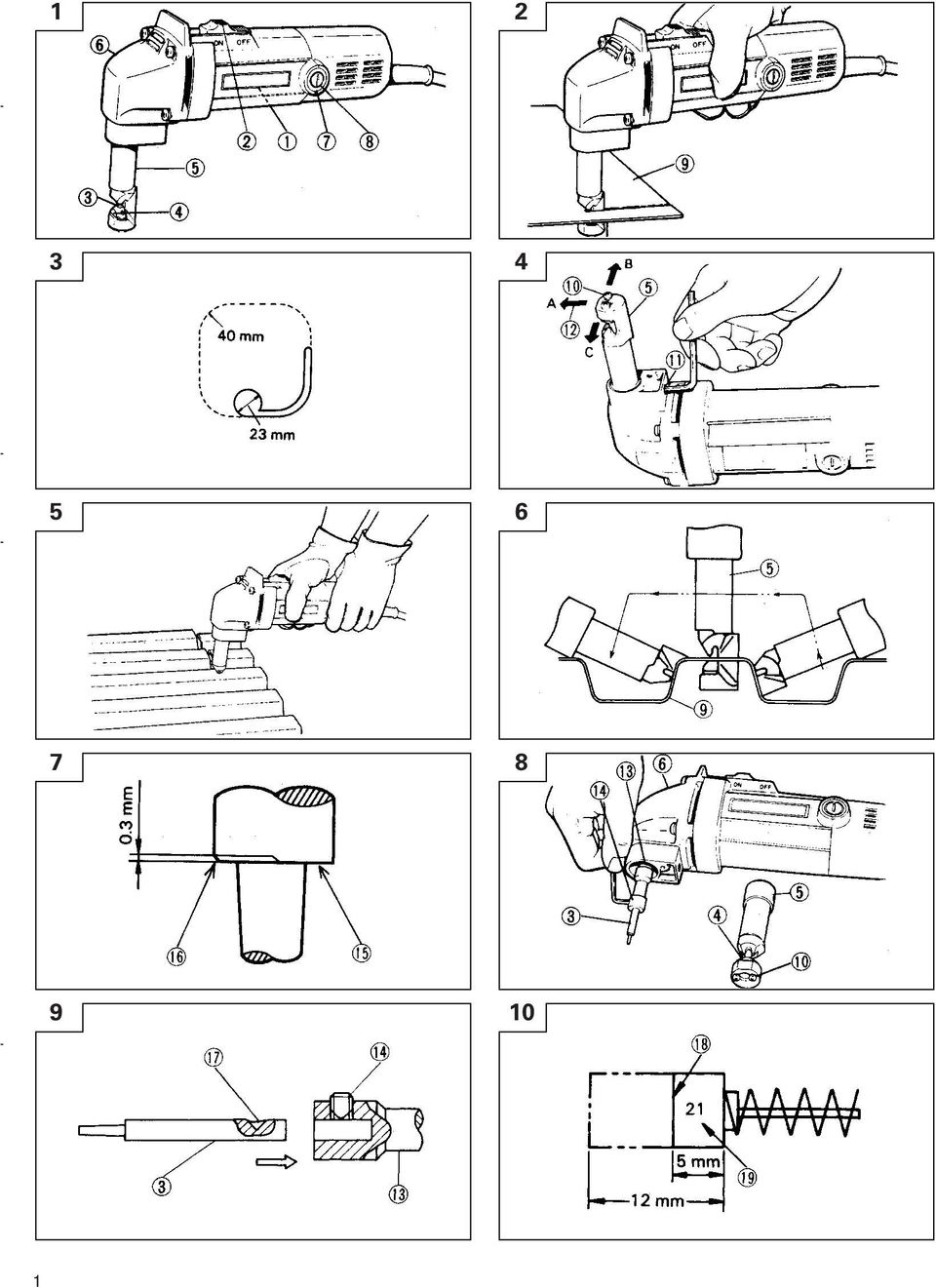
5 English GENERAL OPERATIONAL PRECAUTIONS WARNING! When using electric tools, basic safety precautions should always be followed to reduce the risk of fire, electric shock and personal injury, including the following. Read all these instructions before operating this product and save these instructions. For safe operations: 1. Keep work area clean. Cluttered areas and benches invite injuries. 2. Consider work area environment. Do not expose power tools to rain. Do not use power tools in damp or wet locations. Keep work area well lit. Do not use power tools where there is risk to cause fire or explosion. 3. Guard against electric shock. Avoid body contact with earthed or grounded surfaces. (e.g. pipes, radiators, ranges, refrigerators). 4. Keep children away. Do not let visitors touch the tool or extension cord. All visitors should be kept away from work area. 5. Store idle tools. When not in use, tools should be stored in a dry, high or locked up place, out of reach of children. 6. Do not force the tool. It will do the job better and safer at the rate for which it was intended. 7. Use the right tool. Do not force small tools or attachments to do the job of a heavy duty tool. Do not use tools for purposes not intended; for example, do not use circular saw to cut tree limbs or logs. 8. Dress properly. Do not wear loose clothing or jewery, they can be caught in moving parts. Rubber gloves and non-skid footwear are recommended when working outdoors. Wear protecting hair covering to contain long hair. 9. Use eye protection. Also use face or dust mask if the cutting operation is dusty. 10. Connect dust extraction equipment. If devices are provided for the connection of dust extraction and collection facilities ensure these are connected and properly used. 11. Do not abuse the cord. Never carry the tool by the cord or yank it to disconnect it from the receptacle. Keep the cord away from heat, oil and sharp edges. 12. Secure work. Use clamps or a vise to hold the work. It is safer than using your hand and it frees both hands to operate tool. 13. Do not overreach. Keep proper footing and balance at all times. 14. Maintain tools with care. Keep cutting tools sharp and clean for better and safer performance. Follow instructions for lubrication and changing accessories. Inspect tool cords periodically and if damaged, have it repaired by authorized service center. Inspect extension cords periodically and replace, if damaged. Keep handles dry, clean, and free from oil and grease. 15. Disconnect tools. When not in use, before servicing, and when changing accessories such as blades, bits and cutters. 16. Remove adjusting keys and wrenches. Form the habit of checking to see that keys and adjusting wrenches are removed from the tool before turning it on. 17. Avoid unintentional starting. Do not carry a plugged-in tool with a finger on the switch. Ensure switch is off when plugging in. 18. Use outdoor extension leads. When tool is used outdoors, use only extension cords intended for outdoor use. 19. Stay alert. Watch what you are doing. Use common sense. Do not operate tool when you are tired. 20. Check damaged parts. Before further use of the tool, a guard or other part that is damaged should be carefully checked to determine that it will operate properly and perform its intended function. Check for alignment of moving parts, free running of moving parts, breakage of parts, mounting and any other conditions that may affect its operation. A guard or other part that is damaged should be properly repaired or replaced by an authorized service center unless otherwise indicated in this handling instructions. Have defective switches replaced by an authorized service center. Do not use the tool if the switch does not turn it on and off. 21. Warning The use of any accessory or attachment, other than those recommended in this handling instructions, may present a risk of personal injury. 22. Have your tool repaired by a qualified person. This electric tool is in accordance with the relevant safety requirements. Repairs should only be carried out by qualified persons using original spare parts. Otherwise this may result in considerable danger to the user. PRECAUTIONS ON USING NIBBLER 1. Beware of sharp panel edges. The edge of the plate just cut by the nibbler is very sharp. Take care in not getting hurt by the sharp edge. 2. If shavings get into the machine, it will produce problems or accidents. Do not place the machine on the shavings. 3. Shavings are hot immediately after they are cut. Never touch them with bare hands. 4. Preserve the power cord. Be sure that the power cord is not abraded or cut by the sharp edge of the cut panel. 4

6 English SPECIFICATIONS Voltage (by areas)* (110V, 115V, 120V, 127V, 220V, 230V, 240V) Power Input 400W* Cutting Mild Steel plate(400n/mm 2 ) 1.6 mm capacity Stainless steel plate (600N/mm 2 ) 1.2 mm Aluminium plate (200N/mm 2 ) 2.3 mm Number of strokes at no load Minimum cutting radius Width of nibbling groove Weight (without cord) *Be sure to check the nameplate on product as it is subject to change by areas. 2000/min 40 mm 5 mm 1.7 kg STANDARD ACCESSORIES (1) Hexagon bar wrench... 2 Standard accessories are subject to change without notice. APPLICATIONS Cutting and pocket cutting mild steel, stainless steel, copper and aluminium plates corrugated plates and trapezoidal plates. PRIOR TO OPERATION 1. Power source Ensure that the power source to be utilized conforms to the power requirements specified on the product nameplate. 2. Power switch Ensure that the power switch is in the OFF position. If the plug is connected to a receptacle while the power switch is in the ON position, the power tool will start operating immediately, which could cause a serious accident. 3. Extension cord When the work area is removed from the power source, use an extension cord of sufficient thickness and rated capacity. The extension cord should be kept as short as practicable. 4. Die Inspection Inspect for looseness of the M8 hexagon socket set screw used for mounting the die holder, the M3 machine screws used for mounting the die (see Fig. 4) and the M5 hexagon socket set screws used for mounting the punch (see Fig. 8). Caution should be exercised because, if any of these screws are loose, not only does cutting performance deteriorate but the machine can also be damaged. 5. Lubrication Before use, carefully lubricate the sliding surfaces around the die and punch (see Fig. 1) with a suitable amount of machine oil or spindle oil. 5 CUTTING CAUTION Never try to cut materials that are too large for the capacity of the machine since this may cause damage. Applying cutting oil (spindle oil, machine oil, and so on) along the shearing line may decrease wear of the punch and die. Use care to prevent cutting oil adhering to the housing since the surface may be damaged. The cutting directions of Punch shape (I) (see Fig. 11) are in the 3 directions of A, B and C (see Fig. 4) and these directions can be changed, but punch shape (II) can be cut in direction B only. 1. Cutting plates As shown in Fig. 2, hold the plates being cut parallel with the machine and apply a light force while cutting. When pocket cutting, make a hole 23 mm in diameter or larger, as shown in Fig. 3, and start cutting with the tip of the die holder. 2. Cutting corrugated and trapezoidal plates (1) The cutting direction of this machine can be rotated in 90 increments in 3 directions (A, B and C) (see Fig. 4) by loosening the M8 hexagon socket set screw mounting the die holder. Set the cutting direction in the B or C direction to cut trapezoidal plates. After that, securely tighten the M8 hexagon socket set screw. (2) Grip the machine firmly with both hands as shown in Fig. 5, align with the shape of the trapezoidal plate, push the machine forward until the die holder is at right angles as shown in Fig. 6 and make the cut. REPLACING PUNCH AND DIE CAUTION In this case, be sure to previously disconnect the plug from the power supply. 1. Service Life of the Punch and Die Wear and damage to the cutting edges of the punch and die can greatly influence the cutting operation. Under normal usage, the service life of the punch and die is as shown in the table below. Replace the punch and die promptly when the end of the service life approaches. The punch and die should be replaced at the same time.
 Hexagon bar wrench... 2 Standard accessories are subject to change without notice.")
7 English Cutting materials When the machine is used according to the service life indicated in the above table, the punch will have abrasions as shown in the enlarged diagram of the worn punch tip in Fig. 7. This is when the punch and die should be replaced. CAUTION If the punch and die are used longer than the specified service life, the die holder will be subject to excessive stress and may break off. When a 1.6 mm mild steel trapezoidal plate is cut, wear will be especially quick. Replace the punch and die as soon as possible after reaching the service life. 2. Punch and die replacement (see Fig. 8) CAUTION During the following operations, use care to prevent dirt adhering inside the gear cover, inside the die holder and around the piston. (1) Punch replacement (a) Loosen the M8 hexagon socket set screw mounting the die holder (see Fig. 4) and remove the die holder. (b) Loosen the M5 hexagon socket set screw fastening the punch to the piston and pull out the punch. (c) Insert the new punch while aligning the taper hole of the punch and the direction of the M5 hexagon socket set screw, then securely tighten the hexagon socket set screw.(see Fig. 9). (2) Die replacement Loosen the 2 machine screws and replace the die. (3) Lubricaton When the above replacement operations are completed, apply a suitable amount of machine oil to the sliding surfaces around the punch and die and operate the machine without a load. MAINTENANCE AND INSPECTION Service life cutting lengths of punch and die 1.6 mm Mild steel plates 300 m 1.6 mm Mild steel corrugated and trapezoidal 50 m plates 1.2 mm stainless steel plates 200 m 1. Checking punch and die A worn or defective punch and die will greatly decrease work efficiency. Check and replace them periodically. Refer to Replacing punch and die. 2. Inspecting the mounting screws: Regularly inspect all mounting screws and ensure that they are properly tightened. Should any of the screws be loose, retighten them immediately. Failure to do so could result in serious hazard. 3. Maintenance of the motor The motor unit winding is the very heart of the power tool. Exercise due care to ensure the winding does not become damaged and/or wet with oil or water. 4. Inspecting the carbon brushes (Fig. 10) The motor employs carbon brushes which are consumable parts. Since an excessively worn carbon brush can result in motor trouble, replace the carbon brush with a new one having the same carbon brush No. shown in the figure when it becomes worn to or near the wear limit. In addition, always keep carbon brushes clean and ensure that they slide freely within the brush holders. 5. Replacing carbon brushes Disassemble the brush cap with a screwdriver. The carbon brush can then be easily removed. 6. Service parts list A: Item No. B: Code No. C: No. Used D: Remarks CAUTION Repair, modification and inspection of Hitachi Power Tools must be carried out by an Hitachi Authorized Service Center. This Parts List will be helpful if presented with the tool to the Hitachi Authorized Service Center when requesting repair or other maintenance. In the operation and maintenance of power tools, the safety regulations and standards prescribed in each country must be observed. MODIFICATIONS Hitachi Power Tools are constantly being improved and modified to incorporate the latest technological advancements. Accordingly, some parts (i.e. code numbers and/or design) may be changed without prior notice. NOTE Due to HITACHI s continuing program of research and development, the specifications herein are subject to change without prior notice. IMPORTANT Correct connection of the plug The wires of the main lead are coloured in accordance with the following code: Blue: -Neutral Brown: -Live As the colours of the wires in the main lead of this tool may not correspond with the coloured markings identifying the terminals in your plug proceed as follows: The wire coloured blue must be connected to the terminal marked with the letter N or coloured black. The wire coloured brown must be connected to the terminal marked with the letter L or coloured red. Neither core must be connected to the earth terminal. NOTE This requirement is provided according to BRITISH STANDARD 2769: Therefore, the letter code and colour code may not be applicable to other markets except The United Kingdom. 6

8 English Information concerning airborne noise and vibration The measured values were determined according to EN The typical A-weighted sound pressure level: 80 db (A). Wear ear protection. The typical weighted root mean square acceleration value does not exceed 2.5m/s 2. 7

9 Deutsch ALLGEMEINE VORSICHTSMASSNAHMEN WARNUNG! Bei der Verwendung von Elektrowerkzeugen müssen immer die grundlegenden Vorsichtsmaßnahmen befolgt werden, um das Risiko von Feuer, elektrischem Schlag und persönlicher Verletzung und den nachfolgenden Punkten zu vermeiden. Lesen Sie diese Anweisungen völlig, bevor Sie dieses Erzeugnis verwenden, und bewahren Sie diese Anweisungen auf. Für sicheren Betrieb: 1. Der Arbeitsplatz sollte sauber gehalten werden. Unaufgeräumte Arbeitsplätze und Werkbänke erhöhen die Unfallgefahr. 2. Die Betriebsbedingungen beachten. Elektrowerkzeuge sollten nicht dem Regen ausgesetzt werden. Ebenfalls sollten Sie nicht an feuchten oder nassen Plätzen gebraucht werden. Der Arbeitsplatz sollte gut beleuchtet sein. Verwenden Sie Elektrowerkzeuge nicht an Orten, an denen die Gefahr von Feuer oder Explosion besteht. 3. Schutzmaß nahmen gegen elektrische Schläge treffen. Darauf achten, daß das Gehäuse nicht in Kontakt mit geerdeten Flachen kommt (z.b. Rohre, Radiatoren, Elektroherde, Kühlschränke). 4. Kinder sollten vom Gerät ferngehalten werden. Vermeiden, daß andere Personen mit dem Werkzeung oder Verlängerungskabel in Kontakt kommen. Besucher sollten vom Arbeitsbereich ferngehalten werden. 5. Nicht benutzte Werkzeuge sollten sicher aufbewahrt werden. Sie sollten an einem trockenen und verschließbaren Ort aufbewahrt werden, damit Kinder sie nicht in die Hände bekommen. 6. Werkzeuge sollten nicht mit übermäßiger Gewalt verwendet werden. Ihre Leistung ist besser und sicherer, wenn sie mit der vorgeschriebenen Geschwindigkeit verwendet werden. 7. Nur die korrekten Werkzeuge verwenden. Niemals ein kleineres Werkzeug oder Zusatzgerat für Arbeiten verwenden, die Hochleistungsgerate erfordern. Nur Werkzeuge verwenden, die dem Verwendungszweck entsprechen, d.h. niemals eine Kreissäge zum Sägen von Ästen oder Baumstämmen verwenden. 8. Die richtige Kleidung tragen. Keine lose Kleidung oder Schmuck tragen, da sich lose Kleidungsstücke in den bewegenden Teilen verfangen können. Bei Arbeiten im Freien sollten Gummihandschuhe und rutschfeste Schuhe getragen werden. Tragen Sie eine schützende Haarabdeckung, um langes Haar zurückzuhalten. 9. Es sollte eine Sicherheitsbrille getragen werden. Bei Arbeiten mit Staubentwicklung sollte eine Gesichtsoder Staubmaske getragen werden. 10. Schließen Sie eine Staubabsaugvorrichtung an. Wenn Vorrichtungen für den Anschluß von Staubabsaug- und -sammelvorrichtungen vorhanden sind, so stellen Sie sicher, daß diese angeschlossen sind und richtig verwendet werden. 11. Niemals das Kabel mißbrauchen. Ein Werkzeug niemals am Kabel tragen oder bei Abtrennung von der Steckdose das Kabel harausreißen. Das Kabel sollte gegen Hitze, Öl und scharfe Kanten geschützt werden. 12. Den Arbeitsplatz gut absichern. Zwingen oder einen Schraubstock zur Befestigung des Werkstücks verwenden. Das ist sicherer als die Benutzung der Hände und macht beide Hände zur Bedienung des Werkzeugs frei. 13. Sich niemals weit überbeugen. Immer einen festen Stand und ein sicheres Gleichgewicht bewahren. 14. Die Werkzeuge sollten sorgfältig behandelt werden. Für einen einwandfreien und sicheren Betrieb sollten sie stets scharf sein und saubergehalten werden. Die Anleitungen für schmierung und Austausch des Zuehörs unbedingt einhalten. Die Kabel der Geräte regelmäßig überprüfen und bei Beschädigung durch eine autorisierte Kundendienststelle reparieren lassen. Ebenfalls die Verlägerungskabel regelmäßig überprüfen und bei Beschadigung auswechseln. Die Handgriffe sollten stets trocken und sauber sein, sowie keine Öl- oder Schmierfett stellen aufweisen. 15. Werkzeuge vom Netz trennen, wenn sie nicht benutzt werden, vor Wartungsarbeiten und beim Austausch von Zubehörteilen wie z.b. Blätter, Bohrer und Messer. 16. Alle Stellkeile und Schraubenschlüssel entfernen. Vor Einschaltung des Gerätes darauf achten, daß alle Stellkeile und Schraubenschlüssel entfernt worden sind. 17. Ein unbeabsichtigtes Einschalten sollte vermieden werden. Niemals ein angeschlossenes Werkzeug mit dem Finger am Schalter tragen. Vor Anschluß überprüfen, ob das Gerät ausgeschaltet ist. 18. Im Freien ein Verlängerungskabel verwenden. Nur ein Verlängerungskabel verwenden, das für die Verwendung im Freien markiert ist. 19. Den Arbeitsvorgang immer unter Kontrolle haben. Das Gerät niemals in einem abgespannten Zustand verwenden. 20. Beschädigte Teile überprüfen. Vor Benutzung des Werkzeugs sollten beschädigte Teile oder Schutzvorrichtungen sorgfältig überprüft werden, um festzustellen, ob sie einwandfrei funktionieren und die vorgesehene Funktion erfüllen, Ausrichtung, Verbindungen sowie Anbringung sich bewegender Teile überprüfen. Ebenfalls uberprufen, ob Teile gebrochen sind. Teile oder Schutzvorrichtungen, die beschädigt sind, sollten, wenn in dieser Bedienungsanleitung nichts anderes erwähnt ist, durch eine autorisierte Kundendienststelle ausge wechselt oder repariert werden. Dasselbe gilt für defekte Schalter. Wenn sich das Werkzeug nicht mit dem Schalter einoder ausschalten läßt, sollte das Werkzeug nicht verwendet werden. 21. Warnung Die Verwendung von anderem Zubehör oder anderen Zusätzen als in dieser Bedienungsanleitung empfohlen kann das Risiko einer Körperverletzung einschließen. 22. Lassen Sie Ihr Werkzeug durch qualifiziertes Personal reparieren. Dieses Elektrowerkzeug entspricht den zutreffenden Sicherheitsanforderungen. Reparaturen sollten nur von qualifiziertem Personal unter Verwendung von Originalersatzteilen durchgeführt werden, da sonst beträchtliche Gefahr für den Benutzer auftreten kann. 8

10 Deutsch VORSICHTSMASSNAHMEN BEI BENUTZUNG DES KNABBERS 1. Vorsicht vor scharfen Blechkanten. Die Kante des frisch mit dem Knabber geschnittenen Blechs kann sehr scharf sein. Bei unvorsichtigem Umgang besteht Verletzungsgefahr. 2. Wenn Schneidmaterialien in die Maschine gelangen, verursachen sie Störungen oder Unfälle. Daher die Maschine nicht auf die Schneidmaterialien legen. 3. Schneidmaterialien sind nach dem Schneiden heiß. Niemals mit bloßen Händen anfassen. 4. Vorsicht mit dem Netzkabel. Sicherstellen, daß das Netzkabel nicht durch die scharfen Kanten des geschnittenen Blechs beschädigt oder durchgeschnitten wird. TECHNISCHE DATEN Spannung (je nach Gebiet)* (110V, 115V, 120V, 127V, 220V, 230V, 240V) Leistungsaufnahme 400W* Schneide- Flußstahlplatten (400N/mm 2 ) 1,6 mm kapazität Rostfreie Stahl-Platte (600N/mm 2 ) 1,2 mm Rostfreies Aluminium (200N/mm 2 ) 2,3 mm Anzahl der Stöße ohne Last Minimaler Schneidradius Breite der Knabberrille Gewicht (ohne Kabel) 2000/min 40 mm 5 mm 1,7 kg * Vergessen sie nicht, die Produktangaben auf dem Typenschild zu überprüfen, da sich diese je nach Verkaufsgebiet ändern. STANDARDZUBEHÖRE (1) Sechskantschlüssel... 2 Das Standardzubehör kann ohne vorherige Bekanntmachung jederzeit geändert werden. ANWENDUNGSGEBIETE Schneiden und Taschenschneiden von Eisenblechen, Nirosta-Sahlblechen, Kupfer- und Aluminiumblechen, Wellblechen und Trapezblechen. VOR INBETRIEBNAHME 1. Netzspannung Prüfen, daß die zu verwendende Netzspannung der Angabe auf dem Typenschild entspricht. 2. Netzschalter Prüfen, daß der Netzschalter auf AUS steht. Wenn der Stecker an das Netz angeschlossen wird, während der Schalter auf EIN steht, beginnt das Werkzeung sofort zu laufen, was gefährlich ist. 3. Verlängerungskabel Wenn der Arbeitsbereich nicht in der Nähe des Netzanschlusses liegt, ist ein Verlängerungskabel ausreichenden Querschnitts und ausreichender Nennleistung zu verwenden. Das Verlängerungskabel sollte so kurz wie möglich gehalten werden. 4. Prüfung Die M8 sechskant-steckschraube zum Halten des Formhalters und die M3 Maschinen-Schraube zum Halten der Form auf lockeren Sitz überprüfen (siehe Abb. 4), ebenso die M5 Sechskant-Steckschraube zum Halten des Lochers (siehe Abb. 8). Sorgfältig arbeiten, da bei lockeren Schrauben nicht nur die Schneidleistung beeinträchtigt wird sondern auch die Gefahr von Beschädigung des Gerätes besteht. 5. Schmierung Vor dem Einsatz sorgfältig die Gleitflächen um die Form und den Stanzer mit einer geeigneten Menge Maschinenöl schmieren (siehe Abb. 1). SCHNEIDEN ACHTUNG Niemals versuchen, Materialien zu schneiden, die zu groß für die Kapazität dieser Maschine sind; sonst besteht die Gefahr von Schäden am Gerät. Durch Auftragen von Schneidöl (Spindelöl, Maschinenöl o.ä.) entlang der Schneidlinie kann Verschleiß von Stanzer und Form verringert werden. Nicht Schneidöl auf das Gehäuse kommen lassen; die Oberfläche kann beschädigt werden. Die Schneidrichtungen bei Verwendung von Stanzertyp (I) (siehe Abb. 11) verlaufen in den Richtungen A, B und C (siehe Abb. 4). Diese Richtungen können geändert werden, jedoch ist das Schneiden mit Stanzertyp (II) nur in Richtung B möglich. 1. Schneiden Blechen Wie in Abb. 2 gezeigt, die zu schneidende Platte parallel zum Gerät halten und beim Schneiden leicht drücken. Wenn Taschen geschnitten werden, ein Loch mit 23 mm Durchmesser oder größer machen, wie in Abb. 3 gezeigt, und mit der Spitze des Formhalters zu schneiden beginnen. 2. Schneiden von Wellblechen und Trapezblechen (1) Die Schneidrichtung dieses Gerätes kann in 90 - Schritten in 3 Richtungen (A, B und C) gedreht werden (siehe Abb. 4). Dazu zuerst die M8 Sechskant- Stellschraube des Formhalters lösen. 9

11 Deutsch Die Schneidrichtung auf B oder C stellen, um Trapezbleche zu schneiden. Danach die M8 Sechskant-Stellschraube fest anziehen. (2) Das Gerät fest mit beiden Händen halten, wie in Abb. 5 gezeigt, der Form des Trapezblechs angleichen und das Gerät vorwärts drücken, bis der Formhalter in einem rechten Winkel steht, wie in Abb. 6 gezeigt. Dann mit dem Schneiden beginnen. AUSWECHSELN VON DORN UND STEMPEL VORSICHT In diesem Fall immer vorher den Stecker aus der Steckdose ziehen. 1. Lebensdauer von Stanze und Form Verschleiß und Schäden an den Schneidkanten von Stanze und Form können den Schneidvorgang stark beeinflussen. Bei normalem Betrieb entspricht die Lebensdauer von Stanze und Form den in der untenstehenden Tabelle angegebenen Werten. Die Teile austauschen, wenn das Ende der Lebensdauer erreicht wird. Beide Teile gleichzeitig austauschen. Schneidmaterialien Lebendauer Scheidlängen von Stanze und Form 1,6 mm Eisenblech 300 m 1,6 mm Eisenblech-Wellblech und Trapezblech 50 m 1,2 mm Nirosta-Stahlblech 200 m Bei Betrieb der Maschine entsprechend seiner in der obigen Tabelle aufgeführten Lebensdauer, weist der Stanzer an der Spitze die in dem vergrößerten Diagramm (Abb. 7) gezeigten Abnutzungserscheinungen auf. VORSICHT Die Verwendung von Stanzer und Druckplatte über ihre angegebene Lebensdauer hinaus, führt zu starker Belastung und eventuellem Abbrechen des Halters. Bei Schneiden einer trapezoidförmigen 1,6 mm- Stahlgußplatte treten Verschleißerscheinungen besonders schnell auf. Stanzer und Druckplatte sind deshalb möglichst bald nach Erreichen ihrer Lebensdauergrenze auszutauschen. 2. Austausch von Stanze und Form (siehe Abb.8) VORSICHT Beim folgenden Verfahren darauf achten, nicht Schmutz in das Innere der Zahnradabdeckung, in den Formhalter und in die Nähe des Kolbens kommen zu lassen. (1) Stanzen-Austausch (a) Die M8 Sechskant-Steckschraube zum Halten des Formhalters (siehe Abb. 4) lösen und den Formhalter abnehmen. (b) Die M5 Sechskant-Steckschraube zum Halten der Stanze am Kolben lösen und die Stanze abziehen. (c) Die neue Stanze einführen und dabei das Kegelloch der Stanze und die Richtung der M5 Sechskant- Steckschraube angleichen. Dann die Sechskant- Steckschraube fest anziehen (siehe Abb. 9). (2) Formaustausch Die 2 Maschinenschrauben lösen und die Form austauschen. (3) Schmieren Wenn die obigen Verfahren durchgeführt sind, eine geeignete Menge Maschinenöl auf die Gleitflächen um die Stanze herum auftragen und die Maschine ohne Last arbeiten lassen. WARTUNG UND INSPEKTION 1. Überprüfung von Dorn und Stempel Durch einen abgenutzten oder beschädigten Dorn und Stempel wird die Arbeitseffektivität stark verringert. Daher diese Teile periodisch überprüfen und auswechseln. Siehe Auswechseln von Dorn und Stempel. 2. Inspektion der Befestigungsschrauben: Alle Befestigungsschrauben werden regelmäßig inspiziert und geprüft, ob sie gut angezogen sind. Wenn sich eine der Schrauben lockert, muß sie sofort wieder angezogen werden. Geschieht das nicht, kann das zu erheblichen Gefahren führen. 3. Wartung des Motors Die Motorwicklung ist das Herz des Elektrowerkzeugs. Daher ist besonders sorgfältig darauf zu achten, daß die Wicklung nicht beschädigt wird und/oder mit Öl oder Wasser in BerUhrung kommt. 4. Inspektion der Kohlebürsten (Abb. 10) Im Motor sind Kohlebürsten verwendet, die Verbrauchsteile sind. Übermaßig abgenutzte Kohlenbürsten führen zu Motor, problemen. Deshalb wird eine Kohlebürste durch eine neue ersetzt, die dieselbe Nummer trägt wie auf der Abbildung gezeigt, wenn sie teilweise oder ganz verbraucht ist. Darüber hinaus müssen die Kohlebürsten immer sauber gehalten werden und müssen sich in der Halterung frei bewegen können. 5. Austausch einer Kohlebürste Der Bürstendeckel wird mit einem Steckschlüssel abmontiert. Dann kann die Kohlebürste leicht entfernt werden. 6. Liste der Wartungsteile A: Punkt Nr. B: Code Nr. C: Verwendete Anzahl D: Bemerkungen ACHTUNG Reparatur, Modifikation und Inspektion von Hitachi- Elektrowerkzeugen müssen durch ein autorisiertes Hitachi-Kundendienstzentrum durchgeführt werden. Diese Teileliste ist hilfreich, wenn sie dem autorisierten Hitachi-Kundendienstzentrum zusammen mit dem Werkzeug für Reparatur oder Wartung ausgehändigt wird. Bei Betrieb und Wartung von Elektrowerkzeugen müssen die Sicherheitsvorschriften und Normen beachtet werden. MODIFIKATIONEN Hitachi-Elektrowerkzeuge werden fortwährend verbessert und modifiziert, um die neuesten technischen Fortschritte einzubauen. Dementsprechend ist es möglich, daß einige Teile (z.b. Codenummern bzw. Entwurf) ohne vorherige Benachrichtigung geändert werden. 10

12 Deutsch HINWEIS Aufgrund des ständigen Forschungs-und Entwicklungsprogramms von HITACHI sind Änderungen der hierin gemachten technischen Angaben nicht ausgeschlossen. Information über Betriebslärm und Vibration Die Meßwerte wurden entsprechend EN50144 bestimmt. Der typische A-gewichtete Schalldruckt ist 80 db (A). Bei der Arbeit immer einen Ohrenschutz tragen. Der typische gewichtete Effektiv-Beschleunigungswert überschreitet nicht 2,5 m/s 2. 11
. Bei der Arbeit immer einen Ohrenschutz tragen.")
13 Français PRECAUTIONS GENERALES DE TRAVAIL ATTENTION! Lors de l utilisation d un outillage électrique, les précautions de base doivent être respectées de manière à réduire les risques d incendie, de secousse électrique et de blessure corporelle, y compris les précautions suivantes. Lire ces instructions avant d utiliser le produit et conserver ces instructions pour référence. Pour assurer un fonctionnement sûr: 1. Maintenir l aire de travail propre. Des ateliers ou des établis en désordre risquent de provoquer des accidents. 2. Tenir compte de l environnement de l aire de tra vail. Ne pas exposer les outils électriques à la pluie. Ne pas les utiliser dans des endroits humides. Travailler dans un endroit bien éclairé. Ne pas utiliser d outillage électrique s il existe un risque d incendie ou d explosion. 3. Protection contre une décharge électrique. Eviter tout contact corporel avec des surfaces de mise à la terre telles que les tuyaux, radiateurs, cuisinières et réfrigérateurs. 4. Tenir les enfants éloignés. Ne pas laisser les visiteurs toucher l outil ou son cordon d alimentation. Il est préférable de tenir les visiteurs à l écart de l aire de travail. 5. Ranger les outils non utilisés. Quand on ne les utilise pas, il est recommandé de ranger les outils dans un endroit sec, verrouillé ou hors de portée des enfants. 6. Ne pas forcer l outil. Il fonctionnera mieux et plus sûrement à la vitesse pour laquelle il a été con cu. 7. Utiliser l outil approprié. Ne pas essayer de faire avec un petit outil le travail prevu pour un outil plus important. Toujours utiliser l outil adéquat; par exemple, ne pas se servir d une scie circulaire pour couper des branches d arbres ou des billots de bois. 8. Porter des vêtements appropriés. Ne pas mettre de vêtements flottants ou de bijoux qui risquent d être pris dans les pièces mobiles. Si l on travaille à l extérieur, il est recommandé de porter des gants de caoutchouc et des chaussures à semelles antidérapantes. Veiller à s attacher les cheveux ou à mettre un bonnet si on a les cheveux longs. 9. Porter des lunettes protectrices. Mettre un masque si l opération de coupe crée de la poussière. 10. Relier l équipement d extraction de poussière. Si des dispositifs sont prévus pour le raccordement d installations d extraction et de collection de poussière, s assurer qu ils sont correctement raccordés et utilisés. 11. Prendre soin du fil. Ne jamais transporter l outil en le tenant par le fil et ne pas le débrancher en tirant sur le fil d un coup sec. Tenir le fil à l abri de la chaleur, l éloigner de l huile ou de bords tranchants. 12. Fixer fermement la piêce à travailler. Utiliser des agrafes ou un étau pour la maintenir, C est plus sûr que d utiliser ses mains et cela les libêre pour faire fonctionner l outil. 13. Ne pas présumer de ses forces. Essayer de garder son équilibre en toute circonstance. 14. Entretenir les outils avec soin. Les conserver bien aiguisés et les nettoyer afin d en obtenir les meilleures performances et de pouvoir les utiliser sans danger. Suivre les instructions pour le graissage et le changement des accessoires. Vérifier régulièrement les fils et cordons et s ils sont endommagés, les faire réparer par une personne compétente. Vérifier régulièrement les rallonges et les remplacer si elles sont endommagées. Veiller à ce que les poignées soient toujours sèches et propres, sans huile ni graisse. 15. Debrancher les outils lorsqu on ne les utilise pas, avant toute opération d entretien et lors du changement d accessoire; comme par exemple quand on change les lames, les forets, le fraises, etc. 16. Retirer les clés de réglage. Prendre l habitude de toujours vérifier que les clés de réglage sont bien retirées de l appareil avant de le mettre en marche. 17. Eviter toute mise en marche accidentelle. Ne pas transporter l outil branché avec un doigt sur l interrupteur. S assurer que l interrupteur est sur la position d arrêt quand on branche l outil. 18. Utilisation de rallonges à l extérieur. Quand on utilise l outil à l extérieur, ne se servir que des rallonges prévues pour l extérieur et portant une marque distinctive. 19. Soyez vigilant. Regardez bien ce que vous faites. Faites appel à votre bon sens. N utilisez pas l outil quand vous êtes fatigué. 20. Vérifier les pièces endommagées. Avant d utiliser davantage l outil, vérifier attentivement toute pièce endommagée afin de déterminer si l outil peut fonctionner correctement et effectuer le travail pour lequel il est prévu. Vérifier l alignement et la flexion des piêces mobiles, la cassure des pièces, le montage et toute autre condition risquant d affecter le bon fonctionnement de l outil. Un protecteur ou toute autre pièce endommagée devra être correctement réparé ou remplacé par un service d entretien autorisé, sauf autre indication dans ce mode d emploi. Faire remplacer les interrupteurs défectueux par un service d entretien autorisé. Ne pas utiliser l outil si l interrupteur ne permet pas de le mettre en marche ou de l arrêter. 21. Précaution L utilisation d un accessoire ou dispositif annexe autre que ceux conseillés dans ce mode d emploi peut entraîner un risque de blessure corporelle. 22. Confier la réparation d un outil à un technicien qualifié. Cet outil électrique a été conçu conformément aux règles de sécurité en usage. Les réparations doivent être effectuées par du personnel qualifié utilisant des pièces d origine. Dans le cas contraire, l utilisateur s expose à des risques graves. PRECAUTIONS POUR L UTILISATION DE LA GRIGNOTEUSE 1. Faire attention aux arêtes coupantes du panneau. La bordure de la plaque qui vient d être coupée par la grignoteuse est très coupante. Faire attention à ne pas se blesser avec. 12

14 Français 2. Si des matériaux découpés se prennent dans la machine, cela provoquera des problèmes et parfois des accidents. Ne pas placer la machine sur les matériaux découpés. 3. Après le découpage, les matériaux découpés sont très chauds. Ne jamais les manipuler à mains nues. 4. Faire attention au cordon d alimentation. S assurer que le cordon d alimentation ne risque pas d être touché ou coupé par la bordure coupante du panneau coupé. SPECIFICATIONS Tension (par zone)* (110V, 115V, 120V, 127V, 220V, 230V, 240V) Entrée 400W* Capacité de Plaque en acier doux (400N/mm 2 ) 1,6 mm découpage Plaque d acier inoxydable (600N/mm 2 ) 1,2 mm Plaque d aluminium (200N/mm 2 ) 2,3 mm Nombre de courses sans charge Rayon de découpage minimum Largeur de la rainure de découpage Poids (sans cordon) 2000/min 40 mm 5 mm 1,7 kg * Assurez-vous de vérifier la plaque signalétique se trouvant sur le produit, car elle peut changer suivant les régions. ACCESSOIRES STANDARD (1) Clé à barre hexagonale... 2 Les accessoires standard sont sujets à changement sans préavis. APPLICATIONS Pour la coupe et la découpe de plaques d acier doux, d acier inoxydable, de cuivre, d aluminium, de tôle ondulée et trapézoïdales. AVANT LA MISE EN MARCHE 1. Source de puissance S assurer que la source de puissance àutiliser correspond àla puissance indiquée sur la plaque signalétique du produit. 2. Interrupteur de puissance S assurer que l interrupteur de puissance est en position ARRET. Si la fiche est branchée alors que l interrupteur est sur MARCHE, l outil démarre immédiatement et peut provoquer un grave accident. 3. Fil de rallonge Lorsque la zone de travail est éloignée de la source de puissance, utiliser un fil de rallonge d une épaisseur suffisante et d une capaciténominale suffisante. Le fil de rallonge doit être aussi court que possible. 4. Inspection du moulage Inspecter pour tout relâchement des vis de fixation à tête hexagonale M8 utilisée pour le montage du support de moule, des vis pour machine M3 utilisées pour le montage du moule (voir Fig. 4) et de la vis de fixation à tête hexagonale M5 utilisée pour le montage de la perforatrice (voir Fig. 8). Il est nécessaire de faire attention à ce qu aucune des vis ne soit desserrée car ce n est pas uniquement les performances de coupes qui seront détériorées mais aussi la machine Lubrification Avant l utilisation, huiler soigneusement les surfaces de contact autour du moule et de la perforatrice (voir Fig. 1) avec la quantité d huile machine requise. COUPE ATTENTION Ne jamais essayer de couper des matériaux trop large pour la capacité de la machine car cela risque de l endommager. Appliquer de l huile de coupe (huile d engrenage, huile de machine, etc.) le long de la ligne de coupe pour diminuer l usure de la perforatrice et du moulage. Faire attention à éviter d enlever l huile adhérant au capot car sa surface peut être endommagée. La forme de perforation (I) (voir Fig. 11) peut se découper dans les trois directions A, B et C (voir Fig. 4) et celles-ci peuvent se modifier. Par contre, la forme de perforation (II) ne peut se découper que dans la direction B. 1. Coupe de plaques Comme montré dans la Fig. 2, tenir les plaques à couper parallèles à la machine et appliquer une légère force en coupant. Lors de la découpe, s assurer de faire un trou de 23 mm de diamètre ou plus large, comme montré dans la Fig. 3, puis commencer la découpe avec l extrémité du support du moule. 2. Coupe de plaques de tôle ondulée et trapézoïdales (1) La direction de coupe de cette machine peut être tournée par incréments de 90 dans 3 directions (A, B et C) (voir Fig. 4) en desserrant la vis de fixation à tête hexagonale du support du moule. Régler la direction de coupe dans la direction B ou C pour couper des plaques trapézoïdales. Après cela, resserrer fermement les vis de fixation à tête hexagonale.
* (110V, 115V, 120V, 127V, 220V, 230V, 240V) Entrée 400W* Capacité de Plaque en acier doux (400N/mm 2 ) 1,6 mm découpage Plaque d acier inoxydable (600N/mm 2 ) 1,2 mm")
15 Français (2) Maintenir la machine fermement avec les deux mains comme montré dans Fig. 5. Aligner avec la forme de la plaque trapézoïdale, et pousser la machine vers l avant jusqu à ce que le support du moule soit à angle droit comme montré dans la Fig. 6 et effectuer la coupe. REMPLACEMENT DU POINÇON ET DE LA MATRICE ATTENTION Dans ce cas, s assurer de déconnecter la prise de l alimentation. 1. Durée de vie de la perforatrice et du moule L usure et des dommages sur les arêtes de la perforatrice et du moule influenceront grandement les opérations de coupe. En usage normal, la durée de vie de la perforatrice et du moule correspond à ce qui est montré dans la table ci-dessous. Remplacer la perforatrice et le moule lorsque la durée de vie approche de la fin. La perforatrice et le moule doivent être remplacés en même temps. Matériel de coupe Plaque de métal doux tôle ondulée et trapézoïdale de 1,6 mm Plaque de métal doux, tôle ondulée et trapézoïdale de 1,6 mm Plaque d acier inoxydable de 1,2 mm Durée de vie de la perforatrice et du moule 300 m 50 m 200 m Lorsque l appareil est utilisé conformément au tableau de durée d utilisation mentionné ci-dessus, les abrasions de la perceuse correspondront à celles montrées sur l illustration agrandie de la pointe usée de la perceuse (Fig. 7). La perceuse et la matrice devront être remplacées à ce moment-là. ATTENTION Si la perceuse et la matrice sont utilisées pendant plus longtemps que la durée de service spécifiée, le support de la matrice sera soumis à des contraintes excessives et peut se rompre. L usure sera particulièrement importante en cas de découpe de plaques trapézoïdales de 1,6 mm en acier doux. Il est par conséquent préférable de remplacer la perceuse et la matrice dès que leur durée d utilisation touche à sa fin. 2. Remplacement de la perforatrice et du moule (voir Fig. 8) ATTENTION Pendant les opérations suivantes, faire attention à ce qu il n y ait pas de saleté qui adhère à l intérieur du couvercle d engrenage, dans le support du moule et autour du piston. (1) Remplacement de la perforatrice (a) Desserer la vis de fixation à tête hexagonale M8 du support de moule (voir Fig. 4) et enlever le support de moule. (b) Desserer la vis de fixation à tête hexagonale M5 qui tient la perforatrice au piston et tirer la perforatrice dehors. (c) Insérer la nouvelle perforatrice tout en alignant le trou conique de la perforatrice et la direction de la vis de fixation à tête hexagonale M5. Serrer ensuite fermement la vis de fixation à tête hexagonale (voir Fig. 9). (2) Remplacement du moule Desserrer les 2 vis machine et remplacer le moule. (3) Lubrification Lorsque les opérations de remplacement ci-dessus sont terminées, appliquer la quantité correcte d huile pour machine sur les surfaces de contact autour de la perforatrice et du moule et faire fonctionner la machine à vide. ENTRETIEN ET CONTROLE 1. Contrôle du poinçon et de la matrice Un poinçon et une matrice défectueux ou usés diminueront considérablement l efficacité du travail effectué. Les vérifier et les remplacer périodiquement. Se reporter au paragraphe Remplacement du poinçon et de la matrice. 2. Contrôle des vis de montage Vérifier régulièrement les vis de montage et s assurer qu elles sont correctement serrées. Resserrer immédiatement toute vis desserrée. Sinon, il y a danger sérieux. 3. Entretien du moteur Le bobinage de l ensemble moteur est le coeur même de l outil électro-portatif. Veiller soigneusement à ce que ce bobinage ne soit pas endommagé et/ou mouillé par de l huile ou de l eau. 4. Contrôle des balais en carbone (Fig. 10) Le moteur utilise des balais en carbone qui sont des pièces qui s usent. Comme un balai en carbone trop usé peut détériorer le moteur, le remplacer par un nouveau du même No. que celui montré à la figure quand il est usé ou à la limite d usure. En outre, toujours tenir les balais propres et veiller à ce qu ils coulissent librement dans les supports. 5. Remplacement d un balai en carbone Démonter le capuchon du balai avec un tournevis à petite tête. Le balai en carbone peut se retirer facilement. 6. Liste des pièces de rechange A: No. élément B: No. code C: No. utilisé D: Remarques ATTENTION Les réparations, modifications et inspections des outils électriques Hitachi doivent être confiées à un service après-vente Hitachi agréé. Il sera utile de présenter cette liste de pièces au service après-vente Hitachi agréé lorsqu on apporte un outil nécessitant des réparations ou tout autre entretien. Lors de l utilisation et de l entretien d un outil électrique, respecter les règlements et les normes de sécurité en vigueur dans le pays en question. 14

16 Français MODIFICATIONS Les outils électriques Hitachi sont constamment améliorés et modifiés afin d incorporer les tous derniers progrès technologiques. En conséquence, il est possible que certaines pièces (c.-à-d. no. de code et/ou dessin) soient modifiées sans avis préalable. NOTE Par suite du programme permanent de recherche et de développement HITACHI, ces spécifications peuvent faire l objet de modifications sans avis préalable. Ce produit est conforme aux prescriptions 76/889/CEE et 82/499/CEE. Référence VDE Au sujet du bruit et des vibrations Les valeurs mesurées ont été déterminées en fonction de la norme EN Le niveau de pression acoustique pondéré A est de 80 db (A). Porter un casque de protection. L accélération quadratique pondérée typique n excède pas 2,5 m/s 2. 15

17 Italiano PRECAUZIONI GENERALI ATTENZIONE! Quando si usano elettroutensili, bisogna sempre seguire le precauzioni basilari di sicurezza per ridurre il rischio di incendi, scosse elettriche e lesioni alle persone, tra cui quanto segue. Leggere tutte queste istruzioni prima di usare questo prodotto e conservare le istruzioni. Per un funzionamento sicuro: 1. Mantenere sempre pulita l area dove si lavora. Un area di lavoro sempre pulita aiuta ad evitare incidenti. 2. Tenere nella dovuta considerazione le condizioni dell ambiente di lavoro. Non esporre gli elettroutensili alla pioggia. Non usare gli elettroutensili in luoghi molto umidi o bagnati. Mantenere ben illuminata l area di lavoro. Non usare elettroutentsili dove ci sia il rischio di causare incendi o esplosioni. 3. Fare attenzione alle scosse elettriche. Evitare il contatto del corpo con superfici collegate a terra (p.es. tubi, caloriferi, fornelli, frigoriferi) 4. Tenere lontano i bambini. Non permettere che persone estranee ai lavori tocchino gli elettrouten sili o i cavi della corrente elettrica. Le persone non addette al lavoro non dovrebbero nemmeno avvicinarvisi. 5. Riporre gli elettroutensili non usati in luogo adatto. Quando non utilizzati, gli elettroutensili vanno tenuti in un luogo asciutto, chiusi a chiave o in alto, fuori dalla portata dei bambini. 6. Non forzare mai gli elettroutensili. Qualsiasi lavoro viene eseguito meglio e più velocemente alla velocità per la quale l elettroutensile è stato formulato. 7. Scegliere sempre l utensile elettrico adatto. Non forzare un piccolo elettroutensile o un accessorio a fare un lavoro di un utensile o accessorio più grande. Non usare gli elettroutensili per dei lavori per i quali non sono stati formulati (non usare, per esempio, una sega circolare per tagliare grossi tronchi). 8. Vestirsi in modo adatto. Non portare abiti larghi o gioielli, che potrebbero impigliarsi nelle parti in movimento degli elettroutensili. Lavorando all'ester-no, si raccomanda l uso di guanti di gomma e di scarpe antisdrucciolo. Chi porta capelli lunghi dovrebbe utilizzare un apposita cuffia protettiva. 9. Usare occhiali protettivi. Esegundo dei lavori di taglio che producono molta polvere, usare anche una mascherina antipolvere. 10. Collegare apparecchiature di rimozione della polvere. Se sono forniti dispositivi per il collegamento di apparecchiature di rimozione e raccolta della polvere, assicurarsi che siano collegati e usati correttamente. 11. Non maltrattare il cavo della corrente elettrica. Non trasportare gli elettroutensili prendendoli per il cavo della corrente e non scollegarli dalla presa in tal modo. Tenere il cavo della corrente lontano dal calore, olio ed oggetti taglienti. 12. Lavorare su oggetti fermi. Fissare saldamente l oggetto in una morsa. Èpiù sicuro che non tenendolo fermo con le mani, che restano libere per maneggiare l elettroutensile. 13. Non squilibrare il corpo durante l esecuzione di un lavoro. Stare sempre su due piedi, in equilibrio stabile. 14. Trattare gli utensili elettrici con cura. Tenerli sempre puliti ed affilati per un funzionamento migliore e più sicuro. Seguire le istruzioni date per la lubrificazione e la sostituzione degli accessori. Controllare periodicamente le condizioni del cavo della corrente. Se dovesse essere rovinato, farlo sostituire presso un Centro Assistenza. Non usare cavi di prolungamento rovinati. Mantenere le impugnature sempre pulite, libere soprattutto da olio e grasso. 15. Quando non si usa, prima di eseguire una qualsiasi operazione di manutenzione e prima di intraprendere qualsiasi sostituzione di accessori (lama, punte, ecc.), scollegare sempre l elettroutensile. 16. Togliere sempre le chiavi di regolazione dall attrezzo. E buona abitudine controllare siste maticamente che nessuna chiave di regolazione sia più attaccata all elettroutensile, prima di metterlo in funzione. 17. Evitare che l elettroutensile possa inavvertitamente essere messo in funzione. Non trasportare gli elet troutensili mantenendo il dito sull interruttore, mentre sono collegati alla rete. Prima di collegarli, controllare che l interruttore sia in posizione di spento. 18. Fare uso di cavi di prolungamento per esterni. In questo caso, controllare che il cavo sia adatto per l uso all esterno. 19. Stare sempre attenti. Guardare sempre nel punto in cui si esegue il lavoro. Non usare utensili elettrici se si è stanchi. 20. Controllare qualsiasi parte che sembra danneggiata. Prima di riprendere l uso degli elettroutensili, controllare attentamente che la parte apparentemente danneggiata possa ancora essere usata in modo da assolvere la sua funzione. Controllare che le parti mobili siano nella loro posizione corretta, che nessun pezzo sia rotto, che tutti i pezzi siano montati correttamente, e controllare altri punti importanti per il funzionamento dell utensile elettrico. Qualsiasi pezzo danneggiato deve essere ripa rato o sostituito da un Centro Assistenza autorizzato, a meno che dettagliate istruzioni in proposito siano date nel presente manuale. Fare sostituire gli interruttori difettosi presso un Centro Assistenza autorizzato. Non usare l elettroutensile se non può e acceso o spento per mezzo del suo interruttore. 21. Attenzione L uso di qualsiasi accessorio o attacco diverso da quelli citati nel presente manuale di istruzioni può presentare il rischio di lesioni alle persone. 22. Far riparare l elettroutensile da personale qualificato. Questo elettroutensile è in conformità con le relative norme di sicurezza. Le riparazioni devono essere eseguite solo da personale qualificato usando ricambi originali, altrimenti ne possono derivare considerevoli rischi per l utilizzatore. 16

18 Italiano PRECAUZIONI PER L USO DELLA RODITRICE 1. Fare attenzione ai bordi taglienti del pannello. Il bordo della lastra appena tagliata dalla roditrice è molto tagliente. Fare attenzione a non ferirsi. 2. Se il materiale tagliato dovesse penetrare all interno dell attrezzo, potrebbero prodursi dei problemi o danni. Non disporre mai l attrezzo sopra al materiale tagliato. 3. Immediatamente dopo il taglio, anche il materiale tagliato è molto caldo. Non toccarlo a mani nudel. 4. Fare attenzione al cavo di alimentazione. Assicurarsi che il cavo di alimentazione non sia graffiato o tagliato dal bordo tagliente del pannello tagliato. CARATTERISTICHE Tensione (per zona)* (110V, 115V, 120V, 127V, 220V, 230V, 240V) Ingresso 400W* Capacità Piastra di acciaio tenero (400N/mm 2 ) 1,6 mm di taglio Placche di acciaio inossidabile (600N/mm 2 ) 1,2 mm Piastre di alluminio (200N/mm 2 ) 2,3 mm Numero di corse senza carico Raggio minimo di taglio Larghezza della scanalatura Peso (escluso cavo) 2000/min 40 mm 5 mm 1,7 kg * Accertatevi di aver controllato bene la piastrina perché essa varia da zona a zona. ACCESSORI STANDARD (1) Chiave esagonale... 2 Gli accessori standard possono essere modificati senza preavviso. APPLICAZIONI Taglio e ritaglio di lastre di acciaio dolce, acciaio inossidabile, rame e alluminio, lastre ondulate e lastre trapezoidali. PRIMA DELL USO 1. Alimentazione Assicurarsi che la rete di alimentazione che si vuole usare sia compatibile con le caratteristiche relative all alimentazione di corrente specificate nella piastrina dell apparecchio. 2. Interruttore di corrente Mettere l interruttore in posizione SPENTO. Se la spina è infilata in una presa mentre l interruttore è acceso, l utensile elettrico si mette immediatamente in moto, facilitando il verificarsi di incidenti gravi. 3. Prolunga del cavo Quando l ambiente di lavoro è lontano da una presa di corrente, usare una prolunga del cavo di sufficiente spessore e di prestazione adeguata. La prolunga deve essere più corta possibile. 4. Ispezione della matrice Controllare se la vite con testa a incavo esagonale M8 usata per il montaggio del portamatrice, le viti da macchina M3 usate per il montaggio della matrice (vedere Fig. 4) e le viti di montaggio con testa a incavo esagonale M5 usate per il montaggio del punzone (vedere Fig. 8) sono allentate. E necessario fare attenzione perché se una di queste Cviti è allentata, non solo le prestazioni di taglio sono inferiori, ma la macchina può anche subire danni. 5. Lubrificazione Prima dell uso, lubrificare con cura le parti scorrevoli intorno alla matrice e al punzone (vedere Fig. 1) con una quantità adeguata di olio da macchina. TAGLIO ATTENZIONE Non tentare mai di tagliare materiali troppo grandi per la capacità della macchina perché questo può causare danni. Applicare olio da taglio (olio per perni, olio da macchina, o simili) lungo la linea di tranciatura può diminuire l usura del punzone e della matrice. Fare attenzione per evitare che l olio da taglio aderisca all involucro, perché questo può danneggiarne la superficie. Le direzioni di taglio possibili con il punzone tipo (I) (vedere Fig. 11) sono le direzioni A, B e C (vedere Fig. 4) e possono essere cambiate, ma il punzone tipo (II) può tagliare solo nella direzione B. 1. Taglio di lastre Come mostrato nella Fig. 2 tenere le lastre da tagliare parallele alla macchina e applicare una leggera forza mentre si taglia. Quando si ritaglia, fare un foro di 23 mm, o più di diametro, come mostrato nella Fig. 3, e iniziare a tagliare con la punta del portamatrice. 2. Taglio di lastre ondulate e trapezoidali (1) La direzione di taglio di questa macchina può essere ruotata in scatti di 90 in 3 direzioni (A, B e C) (vedere Fig. 4) allentando la vite di montaggio con testa a incavo esagonale del portamatrice. Regolare la direzione di taglio nella direzione B o C per tagliare lastre trapezoidali. Dopo la regolazione, 17

19 Italiano stringere di nuovo le viti di montaggio con testa a incavo esagonale M8. (2) Afferrare la macchina saldamente con entrambe le mani come mostrato nella Fig. 5, allinearla con la forma della lastra trapezoidale, spingere la macchina in avanti fino a che il portamatrice è ad angolo retto come mostrato nella Fig. 6 ed eseguire il taglio. SOSTITUZIONE DEL PUNZONE E DELLA FILIERA ATTENZIONE In questo caso, assicurarsi di scollegare prima la spina dalla presa di corrente. 1. Durata del punzone e della matrice Usura e danni ai bordi taglienti del punzone e della matrice possono influenzare l operazione di taglio. Nell uso normale la durata del punzone e della matrice è come mostrato nella tabella sotto. Sostituire il punzone e la matrice con prontezza quando si avvicina la fine della loro durata. Il punzone e la matrice devono essere sostituiti allo stesso tempo. Durata in lunghezza di taglio Materiali da tagliare del punzone e della matrice 1,6 mm (lastre di acciaio 300 m dolce) 1,6 mm (lastre ondulate e 50 m trapezoidali di acciaio dolce) 1,2 mm (lastre di acciaio 200 m inossidabile) Se l utensile viene usato secondo i termini di durata d impiego riportati nella tabella sopra, il punzone presenterà abrasioni come illustrato nello schema nell andito della punta consumata del punzone (Fig. 7). A questo punto il punzone e la matrice devono essere sostituiti. ATTENZIONE Se il punzone e la matrice vengono usati più a lungo della durata d impiego prescritta, il supporto della matrice può essere sottoposto a sforzo eccessivo e rompersi. L usura è particolarmente rapida quando si taglia una lastra trapezoidale di acciaio tenero di 1,6 mm. Sostituire il punzone e la matrice appena possibile dopo aver raggiunto i limiti della vita d impiego dell utensile. 2. Sostituzione del punzone e della matrice (vedere Fig. 8) ATTENZIONE Durante le seguenti operazioni fare attenzione a non far penetrare sporcizia nel comparto degli ingranaggi, all interno del portamatrice e intorno al pistone. (1) Sostituzione del punzone (a) Allentare la vite di montaggio con testa a incavo esagonale M8 del portamatrice (vedere Fig. 4) e staccare il portamatrice. (b) Allentare la vite di montaggio con testa a incavo esagonale che assicura il punzone al pistone e estrarre il punzone. (c) Inserire il nuovo punzone allineando il foro cuneiforme del punzone e la direzione della vite di montaggio con testa a incavo esagonale M5 e quindi stringere saldamente la vite di montaggio con testa a incavo esagonale. (vedere Fig. 9) (2) Sostituzione della matrice Allentare le due viti da macchina e sostituire la matrice (3) Lubrificazione Una volta completate le suddette operazioni di sostituzione applicare una quantità adeguata di olio da macchina alle parti scorreoli intorno al punzone e alla matrice e far funzionare la macchina senza un carico. MANUTENZONE ED CONTROLLI 1. Controllo del punzone e della filiera Se punzone o filiera sono difettosi o consumati, l efficienza dell attrezzo ne soffre. Controllarli e sostituirli periodicamente. Vedere Sostituzione del punzone e della filiera. 2. Controllo delle viti di tenuta Controllare regolarmente tutte le viti di tenuta e assicurarsi che siano esclusìvamente serrate. Nel caso che una di queste viti dovesse allentarsi riserrarla immediatamente. Se si non ottiene di farlo, si puó causare un grave incidente. 3. Manutenzione del motore L avvolgimento del motore il vero e proprio cuore degli attezzi elettrici. Fare attenzione a non danneggiare l avvolgimento e/o non bagnarlo con olio o acqua. 4. Controllo delle spazzole di carbone (Fig. 10) Il motore impiega spazzole di carbone che sono materiali di consumo. Poiché una spazzola di carbone troppo larga può creare fastidi al motore, sostituire la spazzola con una dello stesso numero indicato nella figura quando essa è logora fino al limite del regolamento e quasi. Tenere inoltre sempre pulite le spazzole di carbone e fare in modo che esse scorrano liberamente nell interno del portaspazzola. 5. Sostituzione di una spazzola di carbone Togliere la capsula della spazzola con un cacciavite a taglio. La spazzola puó cosí essere agevolmente rimossa. 6. Lista dei pezzi di ricambio A: N. voce B: N. codice C: N. uso D: Note CAUTELA Riparazioni, modifiche e ispezioni di utensili elettrici Hitachi devono essere eseguite da un centro assistenza Hitachi autorizzato. Questa lista dei pezzi torna utile se viene presentata con l utensile al centro assistenza Hitachi autorizzato quando si richiedono riparazioni o altri interventi di manutenzione. Nell uso e nella manutenzione degli utensili elettrici devono essere osservate le normative di sicurezza e i criteri prescritti in ciascun paese. 18

20 Italiano MODIFICHE Gli utensili elettrici Hitachi vengono continuamente migliorati e modificati per includere le più recenti innovazioni tecnologiche. Di conseguenza, alcuni pezzi (p.es. numero di codice e/o design) possono essere modificati senza preavviso. NOTA A causa del continuo programma di ricerca e sviluppo della HITACHI, le caratteristiche riportate in questo foglio sono soggette a cambiamenti senza preventiva comunicazione. Informazioni riguardanti i rumori trasmessi dall aria e le vibrazioni I valori misurati sono stati determinati in conformità a EN Il livello di pressione sonora pesato A tipico è di 80 db (A). Indossare protezioni per le orecchie. Il valore tipico di accelerazione quadrata media a radice pesata non supera 2,5m/s 2. 19

G 10SD2 G 12S2 G 13SD
 Disc Grinder G 10SD2 G 12S2 G 13SD Handling instructions G13SD Read through carefully and understand these instructions before use. 1 2 1 2 3 3 88 8 4 6 5 17 mm 6 mm 9 7 4! @ 0 2 English 1 Wrench 2 Wheel
La Déduction naturelle
 La Déduction naturelle Pierre Lescanne 14 février 2007 13 : 54 Qu est-ce que la déduction naturelle? En déduction naturelle, on raisonne avec des hypothèses. Qu est-ce que la déduction naturelle? En déduction
the total number of electrons passing through the lamp.
 1. A 12 V 36 W lamp is lit to normal brightness using a 12 V car battery of negligible internal resistance. The lamp is switched on for one hour (3600 s). For the time of 1 hour, calculate (i) the energy
Tipologie installative - Installation types Type d installation - Installationstypen Tipos de instalación - Τυπολογίες εγκατάστασης
 AMPADE MOOCROMATICHE VIMAR DIMMERABII A 0 V~ - VIMAR 0 V~ DIMMABE MOOCHROME AMP AMPE MOOCHROME VIMAR VARIATEUR 0 V~ - DIMMERFÄHIGE MOOCHROMATICHE AMPE VO VIMAR MIT 0 V~ ÁMPARA MOOCROMÁTICA VIMAR REGUABE
Capacitors - Capacitance, Charge and Potential Difference
 Capacitors - Capacitance, Charge and Potential Difference Capacitors store electric charge. This ability to store electric charge is known as capacitance. A simple capacitor consists of 2 parallel metal
Strain gauge and rosettes
 Strain gauge and rosettes Introduction A strain gauge is a device which is used to measure strain (deformation) on an object subjected to forces. Strain can be measured using various types of devices classified
[1] P Q. Fig. 3.1
![[1] P Q. Fig. 3.1](/thumbs/79/80362156.jpg "[1] P Q. Fig. 3.1") 1 (a) Define resistance....... [1] (b) The smallest conductor within a computer processing chip can be represented as a rectangular block that is one atom high, four atoms wide and twenty atoms long. One
1 (a) Define resistance....... [1] (b) The smallest conductor within a computer processing chip can be represented as a rectangular block that is one atom high, four atoms wide and twenty atoms long. One
Περιεχόμενα / Contents
 Aερόθερμo / Fan Heater PTC-906 Περιεχόμενα / Contents GR... Σελίδες 3-8 EN... Pages 9-11 2 GR Ευχαριστούμε που επιλέξατε μια συσκευή της γκάμας θερμαντικών IZZY. Σημαντικές Οδηγίες Ασφαλείας Τα Μέρη της
English PDFsharp is a.net library for creating and processing PDF documents 'on the fly'. The library is completely written in C# and based
 English PDFsharp is a.net library for creating and processing PDF documents 'on the fly'. The library is completely written in C# and based exclusively on safe, managed code. PDFsharp offers two powerful
Montage - Raccordement Implantation EURO-RELAIS MINI & BOX. Mini & Box
 Montage - Raccordement Implantation EURO-RELAIS MINI & BOX 3 Fiche technique EURO-RELAIS MINI & BOX DESCRIPTIF La borne Euro-Relais MINI est en polyester armé haute résistance totalement neutre à la corrosion
NMBTC.COM /
 Common Common Vibration Test:... Conforms to JIS C 60068-2-6, Amplitude: 1.5mm, Frequency 10 to 55 Hz, 1 hour in each of the X, Y and Z directions. Shock Test:...Conforms to JIS C 60068-2-27, Acceleration
2 Composition. Invertible Mappings
 Arkansas Tech University MATH 4033: Elementary Modern Algebra Dr. Marcel B. Finan Composition. Invertible Mappings In this section we discuss two procedures for creating new mappings from old ones, namely,
Instruction Execution Times
 1 C Execution Times InThisAppendix... Introduction DL330 Execution Times DL330P Execution Times DL340 Execution Times C-2 Execution Times Introduction Data Registers This appendix contains several tables
DISC GRINDER WINKELSCHLEIFER MEULEUSE SMERIGLIATRICE ANGOLARE HAAKSE SLIJPMACHINE AMOLADORA ANGULAR REBARBADORA ΓΩNIAKOI TPOXOI ΛEIANΣEΩΣ/KOΠHΣ G12SG
 DISC GRINDER WINKELSCHLEIFER MEULEUSE SMERIGLIATRICE ANGOLARE HAAKSE SLIJPMACHINE AMOLADORA ANGULAR REBARBADORA ΓΩNIAKOI TPOXOI ΛEIANΣEΩΣ/KOΠHΣ G 10SG G 12SG G12SG Read through carefully and understand
Surface Mount Multilayer Chip Capacitors for Commodity Solutions
 Surface Mount Multilayer Chip Capacitors for Commodity Solutions Below tables are test procedures and requirements unless specified in detail datasheet. 1) Visual and mechanical 2) Capacitance 3) Q/DF
SABER SAW TIGERSÄGE SCIE SABRE SEGHETTO ALTERNATIVO DIRITTO SCHROBZAAGMACHINE SIERRA SABLE SERRA SABRE ΣΠΑΘΟΣΕΓΑ CR10V CR12 CR12V
 SABER SAW TIGERSÄGE SCIE SABRE SEGHETTO ALTERNATIVO DIRITTO SCHROBZAAGMACHINE SIERRA SABLE SERRA SABRE ΣΠΑΘΟΣΕΓΑ CR10V CR12 CR12V Read through carefully and understand these instructions before use. Diese
Code Breaker. TEACHER s NOTES
 TEACHER s NOTES Time: 50 minutes Learning Outcomes: To relate the genetic code to the assembly of proteins To summarize factors that lead to different types of mutations To distinguish among positive,
Modbus basic setup notes for IO-Link AL1xxx Master Block
 n Modbus has four tables/registers where data is stored along with their associated addresses. We will be using the holding registers from address 40001 to 49999 that are R/W 16 bit/word. Two tables that
Precision Metal Film Fixed Resistor Axial Leaded
 Features EIA standard colour-coding Non-Flame type available Low noise and voltage coefficient Low temperature coefficient range Wide precision range in small package Too low or too high ohmic value can
ΚΥΠΡΙΑΚΗ ΕΤΑΙΡΕΙΑ ΠΛΗΡΟΦΟΡΙΚΗΣ CYPRUS COMPUTER SOCIETY ΠΑΓΚΥΠΡΙΟΣ ΜΑΘΗΤΙΚΟΣ ΔΙΑΓΩΝΙΣΜΟΣ ΠΛΗΡΟΦΟΡΙΚΗΣ 19/5/2007
 Οδηγίες: Να απαντηθούν όλες οι ερωτήσεις. Αν κάπου κάνετε κάποιες υποθέσεις να αναφερθούν στη σχετική ερώτηση. Όλα τα αρχεία που αναφέρονται στα προβλήματα βρίσκονται στον ίδιο φάκελο με το εκτελέσιμο
VENERE. GR. Οδηγός Χρήσης EN. User Guide
 GR. Οδηγός Χρήσης EN. User Guide ΣΗΜΑΝΤΙΚΟ! ΚΡΑΤΗΣΤΕ ΓΙΑ ΜΕΛΛΟΝΤΙΚΗ ΑΝΑΦΟΡΑ: ΔΙΑΒΑΣΤΕ ΠΡΟΣΕΚΤΙΚΑ Κίνδυνος από φωτιά και άλλες πηγές έντονης θερμότητας, όπως ηλεκτρικές αντιστάσεις, υγραέριο, φωτιά κλπ,
MS SERIES MS DESK TOP ENCLOSURE APPLICATION EXAMPLE FEATURE. Measuring instruments. Power supply equipments
 MS SERIES MS DESK TOP ENCLOSURE FEATURE Available in 176 sizes. Screws are not appeared on the surface. Usable as rack mount case with optinal mounting bracket. There are no ventilation hole for cover
4K HDMI Splitter 1x4. User s Guide / Bedienungsanleitung / Εγχειρίδιο Χρήστη
 4K HDMI Splitter 1x4 User s Guide / Bedienungsanleitung / Εγχειρίδιο Χρήστη INTRODUCTION The EDISION 4K HDMI Splitter 1x4 uses a single HDMI input source, to distribute it to 4 HDMI outputs. The splitter
 60 61 62 63 64 65 Ο Δ Η Γ Ι Ε Σ Σ Υ Ν Τ Η Ρ Η Σ Η Σ Τ Ω Ν Κ Ο Υ Φ Ω Μ Α Τ Ω Ν Ι Ν S T R U C T I N O N S C O N C E R N I N G Τ Η Ε C A S E M E N T S M A I N T E N A N C E Ο τακτικός καθαρισμός των βαμμένων
HOMEWORK 4 = G. In order to plot the stress versus the stretch we define a normalized stretch:
 HOMEWORK 4 Problem a For the fast loading case, we want to derive the relationship between P zz and λ z. We know that the nominal stress is expressed as: P zz = ψ λ z where λ z = λ λ z. Therefore, applying
0.635mm Pitch Board to Board Docking Connector. Lead-Free Compliance
 .635mm Pitch Board to Board Docking Connector Lead-Free Compliance MINIDOCK SERIES MINIDOCK SERIES Features Specifications Application.635mm Pitch Connector protected by Diecasted Zinc Alloy Metal Shell
Door Hinge replacement (Rear Left Door)
") Door Hinge replacement (Rear Left Door) We will continue the previous article by replacing the hinges of the rear left hand side door. I will use again the same procedure and means I employed during the
Door Hinge replacement (Rear Left Door) We will continue the previous article by replacing the hinges of the rear left hand side door. I will use again the same procedure and means I employed during the
Homework 8 Model Solution Section
 MATH 004 Homework Solution Homework 8 Model Solution Section 14.5 14.6. 14.5. Use the Chain Rule to find dz where z cosx + 4y), x 5t 4, y 1 t. dz dx + dy y sinx + 4y)0t + 4) sinx + 4y) 1t ) 0t + 4t ) sinx
Συστήματα Διαχείρισης Βάσεων Δεδομένων
 ΕΛΛΗΝΙΚΗ ΔΗΜΟΚΡΑΤΙΑ ΠΑΝΕΠΙΣΤΗΜΙΟ ΚΡΗΤΗΣ Συστήματα Διαχείρισης Βάσεων Δεδομένων Φροντιστήριο 9: Transactions - part 1 Δημήτρης Πλεξουσάκης Τμήμα Επιστήμης Υπολογιστών Tutorial on Undo, Redo and Undo/Redo
Right Rear Door. Let's now finish the door hinge saga with the right rear door
 Right Rear Door Let's now finish the door hinge saga with the right rear door You may have been already guessed my steps, so there is not much to describe in detail. Old upper one file:///c /Documents
3.4 SUM AND DIFFERENCE FORMULAS. NOTE: cos(α+β) cos α + cos β cos(α-β) cos α -cos β
 cos α + cos β cos(α-β) cos α -cos β") 3.4 SUM AND DIFFERENCE FORMULAS Page Theorem cos(αβ cos α cos β -sin α cos(α-β cos α cos β sin α NOTE: cos(αβ cos α cos β cos(α-β cos α -cos β Proof of cos(α-β cos α cos β sin α Let s use a unit circle
3.4 SUM AND DIFFERENCE FORMULAS Page Theorem cos(αβ cos α cos β -sin α cos(α-β cos α cos β sin α NOTE: cos(αβ cos α cos β cos(α-β cos α -cos β Proof of cos(α-β cos α cos β sin α Let s use a unit circle
b. Use the parametrization from (a) to compute the area of S a as S a ds. Be sure to substitute for ds!
 to compute the area of S a as S a ds. Be sure to substitute for ds!") MTH U341 urface Integrals, tokes theorem, the divergence theorem To be turned in Wed., Dec. 1. 1. Let be the sphere of radius a, x 2 + y 2 + z 2 a 2. a. Use spherical coordinates (with ρ a) to parametrize.
MTH U341 urface Integrals, tokes theorem, the divergence theorem To be turned in Wed., Dec. 1. 1. Let be the sphere of radius a, x 2 + y 2 + z 2 a 2. a. Use spherical coordinates (with ρ a) to parametrize.
MSN DESK TOP ENCLOSURE WITH STAND / CARRYING HANDLE
 MSN SERIES MSN DESK TOP ENCLOSURE WITH STAND / CARRYING HANDLE W H FEATURE Available in 176 sizes. Stand / carrying handle can be adjusted in 30 degree. Maximum load is kg. There are no ventilation hole
Aluminum Electrolytic Capacitors (Large Can Type)
") Aluminum Electrolytic Capacitors (Large Can Type) Snap-In, 85 C TS-U ECE-S (U) Series: TS-U Features General purpose Wide CV value range (33 ~ 47,000 µf/16 4V) Various case sizes Top vent construction
Aluminum Electrolytic Capacitors (Large Can Type) Snap-In, 85 C TS-U ECE-S (U) Series: TS-U Features General purpose Wide CV value range (33 ~ 47,000 µf/16 4V) Various case sizes Top vent construction
Tipologie installative - Installation types Types d installation - Die einbauanweisungen Tipos de instalación - Τυπολογίες εγκατάστασης
 Types d installation Die einbauanweisungen Tipos de instalación Τυπολογίες εγκατάστασης AMPADE MOOCROMATICHE VIMAR DIMMERABII A 0 V~ MOOCHROME DIMMABE AMP VIMAR 0 V~ AMPE MOOCHROME VIMAR DIMMABE 0 V~ EUCHTE
Advanced Subsidiary Unit 1: Understanding and Written Response
 Write your name here Surname Other names Edexcel GE entre Number andidate Number Greek dvanced Subsidiary Unit 1: Understanding and Written Response Thursday 16 May 2013 Morning Time: 2 hours 45 minutes
Assalamu `alaikum wr. wb.
 LUMP SUM Assalamu `alaikum wr. wb. LUMP SUM Wassalamu alaikum wr. wb. Assalamu `alaikum wr. wb. LUMP SUM Wassalamu alaikum wr. wb. LUMP SUM Lump sum lump sum lump sum. lump sum fixed price lump sum lump
Aluminum Electrolytic Capacitors
 Aluminum Electrolytic Capacitors Snap-In, Mini., 105 C, High Ripple APS TS-NH ECE-S (G) Series: TS-NH Features Long life: 105 C 2,000 hours; high ripple current handling ability Wide CV value range (47
Bbc7000 ΦΟΡΤΙΣΤΗΣ - ΕΚΚΙΝΗΤΗΣ ΜΠΑΤΑΡΙΑΣ. Art Nr: Owner s manual. Μετάφραση του πρωτοτύπου των οδηγιών χρήσης
 Bbc7000 ΦΟΡΤΙΣΤΗΣ - ΕΚΚΙΝΗΤΗΣ ΜΠΑΤΑΡΙΑΣ Μετάφραση του πρωτοτύπου των οδηγιών χρήσης Art Nr: 022213 Owner s manual Διαβάστε προσεχτικά όλες τις οδηγίες χρήσης και ασφάλειας πριν την λειτουργία του μηχανήματος.
Η ΕΝΕΡΓΕΙΑΚΗ ΣΗΜΑΝΣΗ ΚΑΙ ERP
 Η ΕΝΕΡΓΕΙΑΚΗ ΣΗΜΑΝΣΗ ΚΑΙ ERP 2 1 ΠΛΑΙΣΙΟ ΓΙΑΤΙ ΕΝΕΡΓΕΙΑΚΗ ΣΗΜΑΝΣΗ ΚΑΙ ErP? Αντιμετωπίζοντας την κλιματική αλλαγή, διασφαλίζοντας την ασφάλεια της παροχής ενέργειας2 και την αύξηση της ανταγωνιστικότητα
Potential Dividers. 46 minutes. 46 marks. Page 1 of 11
 Potential Dividers 46 minutes 46 marks Page 1 of 11 Q1. In the circuit shown in the figure below, the battery, of negligible internal resistance, has an emf of 30 V. The pd across the lamp is 6.0 V and
EE512: Error Control Coding
 EE512: Error Control Coding Solution for Assignment on Finite Fields February 16, 2007 1. (a) Addition and Multiplication tables for GF (5) and GF (7) are shown in Tables 1 and 2. + 0 1 2 3 4 0 0 1 2 3
Bulletin 1489 UL489 Circuit Breakers
 Bulletin 489 UL489 Circuit Breakers Tech Data 489-A Standard AC Circuit Breaker 489-D DC Circuit Breaker 489-A, AC Circuit Breakers 489-D, DC Circuit Breakers Bulletin 489-A Industrial Circuit Breaker
38BXCS STANDARD RACK MODEL. DCS Input/Output Relay Card Series MODEL & SUFFIX CODE SELECTION 38BXCS INSTALLATION ORDERING INFORMATION RELATED PRODUCTS
 DCS Input/Output Relay Card Series STANDARD RACK MODEL 38BXCS MODEL & SUFFIX CODE SELECTION 38BXCS MODEL CONNECTOR Y1 :Yokogawa KS2 cable use Y2 :Yokogawa KS9 cable use Y6 :Yokogawa FA-M3/F3XD32-3N use
safty reasons. Disregarding could result in serious injury. Disregarding could result in injury or product damage. Forbidden.
 The following safety precautions are given throughout this manual. They must be strictly followed to protect those who install, use or maintain this product as well as to protect players, visitors and
For safty reasons. Disregarding could result in serious injury. Disregarding could result in injury or product damage. Forbidden.
 The following safety precautions are given throughout this manual. They must be strictly followed to protect those who install, use or maintain this product as well as to protect players, visitors and
H 65SB. Demolition Hammer Hammer Marteau de demolition Demolitore Hakhamer Martillo Martelo Κρουστικο
 Demolition Hammer Hammer Marteau de demolition Demolitore Hakhamer Martillo Martelo Κρουστικο H 65SB Read through carefully and understand these instructions before use. Diese Anleitung vor Benutzung des
Επιτραπέζιος Η/Υ K30AM / K30AM-J Εγχειρίδιο χρήστη
 Επιτραπέζιος Η/Υ K30AM / K30AM-J Εγχειρίδιο χρήστη GK9380 Ελληνικα Πρώτη Έκδοση Μάιος 2014 Copyright 2014 ASUSTeK Computer Inc. Διατηρούνται όλα τα δικαιώματα. Απαγορεύεται η αναπαραγωγή οποιουδήποτε τμήματος
For safty reasons. Disregarding could result in serious injury. Disregarding could result in injury or product damage. Forbidden.
 The following safety precautions are given throughout this manual. They must be strictly followed to protect those who install, use or maintain this product as well as to protect players, visitors and
ΟΔΗΓΙΕΣ ΣΥΝΑΡΜΟΛΟΓΗΣΗΣ/ ASSEMBLY INSTRUCTION ΤΟΜΜΥ ΚΡΕΒΑΤΙ/BED
 ΟΔΗΓΙΕΣ ΣΥΝΑΡΜΟΛΟΓΗΣΗΣ/ ASSEMBLY INSTRUCTION ΤΟΜΜΥ ΚΡΕΒΑΤΙ/BED 1. Παρακαλώ πολύ διαβάστε προσεκτικά τις οδηγίες πριν την συναρμολόγηση/ Please read the instructions carefully. 2. Παρακαλώ πολύ όπως ελέγξτε
Approximation of distance between locations on earth given by latitude and longitude
 Approximation of distance between locations on earth given by latitude and longitude Jan Behrens 2012-12-31 In this paper we shall provide a method to approximate distances between two points on earth
Session novembre 2009
 ΥΠΟΥΡΓΕΙΟ ΕΘΝΙΚΗΣ ΠΑΙΔΕΙΑΣ ΚΑΙ ΘΡΗΣΚΕΥΜΑΤΩΝ ΚΡΑΤΙΚΟ ΠΙΣΤΟΠΟΙΗΤΙΚΟ ΓΛΩΣΣΟΜΑΘΕΙΑΣ MINISTÈRE GREC DE L ÉDUCATION NATIONALE ET DES CULTES CERTIFICATION EN LANGUE FRANÇAISE NIVEAU ÉPREUVE B1 sur l échelle proposée
Matrices and Determinants
 Matrices and Determinants SUBJECTIVE PROBLEMS: Q 1. For what value of k do the following system of equations possess a non-trivial (i.e., not all zero) solution over the set of rationals Q? x + ky + 3z
Επιτραπέζιος Η/Υ ASUS M12AD and M52AD Εγχειρίδιο χρήστη
 Επιτραπέζιος Η/Υ ASUS M12AD and M52AD Εγχειρίδιο χρήστη M12AD M52AD GK9559 Πρώτη Έκδοση Ιούλιος 2014 Copyright 2014 ASUSTeK Computer Inc. Διατηρούνται όλα τα δικαιώματα. Απαγορεύεται η αναπαραγωγή οποιουδήποτε
Math 6 SL Probability Distributions Practice Test Mark Scheme
 Math 6 SL Probability Distributions Practice Test Mark Scheme. (a) Note: Award A for vertical line to right of mean, A for shading to right of their vertical line. AA N (b) evidence of recognizing symmetry
Bid5500 ΚΡΟΥΣΤΙΚΟ ΔΡΑΠΑΝΟ. Owner s manual. Μετάφραση του πρωτοτύπου των οδηγιών χρήσης
 Bid5500 ΚΡΟΥΣΤΙΚΟ ΔΡΑΠΑΝΟ Μετάφραση του πρωτοτύπου των οδηγιών χρήσης Owner s manual Βασικά χαρακτηριστικά 1. Τσόκ 2. Διακόπτης ενεργοποίησης απενεργοποίησης λειτουργίας κρούσης 3. Ράβδος-στοπ βάθους διάτρησης
ΟΔΗΓΙΕΣ ΕΓΚΑΤΑΣTΑΣΗΣ ΓΙΑ ΠΑΤΩΜΑ WPC INSTALLATION GUIDE FOR WPC DECKING
 1/12 ΟΔΗΓΙΕΣ ΕΓΚΑΤΑΣTΑΣΗΣ ΓΙΑ ΠΑΤΩΜΑ WPC INSTALLATION GUIDE FOR WPC DECKING Ανοίγουμε τρύπες Ø8 x 80mm στο σημείο κατασκευής, με τρυπάνι. To προτεινόμενο πλάτος και μήκος μεταξύ των 2 οπών να είναι 30-35εκ.,
CHAPTER 25 SOLVING EQUATIONS BY ITERATIVE METHODS
 CHAPTER 5 SOLVING EQUATIONS BY ITERATIVE METHODS EXERCISE 104 Page 8 1. Find the positive root of the equation x + 3x 5 = 0, correct to 3 significant figures, using the method of bisection. Let f(x) =
Γιπλυμαηική Δπγαζία. «Ανθπυποκενηπικόρ ζσεδιαζμόρ γέθςπαρ πλοίος» Φοςζιάνηρ Αθανάζιορ. Δπιβλέπυν Καθηγηηήρ: Νηθφιανο Π. Βεληίθνο
 ΔΘΝΙΚΟ ΜΔΣΟΒΙΟ ΠΟΛΤΣΔΥΝΔΙΟ ΥΟΛΗ ΝΑΤΠΗΓΩΝ ΜΗΥΑΝΟΛΟΓΩΝ ΜΗΥΑΝΙΚΩΝ Γιπλυμαηική Δπγαζία «Ανθπυποκενηπικόρ ζσεδιαζμόρ γέθςπαρ πλοίος» Φοςζιάνηρ Αθανάζιορ Δπιβλέπυν Καθηγηηήρ: Νηθφιανο Π. Βεληίθνο Σπιμελήρ Δξεηαζηική
H 60MA H 60MB. Demolition Hammer Hammer Marteau de demolition Demolitore Hakhamer Martillo Martelo Κpoyεtiko
 Demolition Hammer Hammer Marteau de demolition Demolitore Hakhamer Martillo Martelo Κpoyεtiko H 60MA H 60MB H60MB Read through carefully and understand these instructions before use. Diese Anleitung vor
ΚΥΠΡΙΑΚΗ ΕΤΑΙΡΕΙΑ ΠΛΗΡΟΦΟΡΙΚΗΣ CYPRUS COMPUTER SOCIETY ΠΑΓΚΥΠΡΙΟΣ ΜΑΘΗΤΙΚΟΣ ΔΙΑΓΩΝΙΣΜΟΣ ΠΛΗΡΟΦΟΡΙΚΗΣ 6/5/2006
 Οδηγίες: Να απαντηθούν όλες οι ερωτήσεις. Ολοι οι αριθμοί που αναφέρονται σε όλα τα ερωτήματα είναι μικρότεροι το 1000 εκτός αν ορίζεται διαφορετικά στη διατύπωση του προβλήματος. Διάρκεια: 3,5 ώρες Καλή
Εργαστήριο Ανάπτυξης Εφαρμογών Βάσεων Δεδομένων. Εξάμηνο 7 ο
 Εργαστήριο Ανάπτυξης Εφαρμογών Βάσεων Δεδομένων Εξάμηνο 7 ο Procedures and Functions Stored procedures and functions are named blocks of code that enable you to group and organize a series of SQL and PL/SQL
Econ 2110: Fall 2008 Suggested Solutions to Problem Set 8 questions or comments to Dan Fetter 1
 Eon : Fall 8 Suggested Solutions to Problem Set 8 Email questions or omments to Dan Fetter Problem. Let X be a salar with density f(x, θ) (θx + θ) [ x ] with θ. (a) Find the most powerful level α test
The challenges of non-stable predicates
 The challenges of non-stable predicates Consider a non-stable predicate Φ encoding, say, a safety property. We want to determine whether Φ holds for our program. The challenges of non-stable predicates
The Simply Typed Lambda Calculus
 Type Inference Instead of writing type annotations, can we use an algorithm to infer what the type annotations should be? That depends on the type system. For simple type systems the answer is yes, and
Phys460.nb Solution for the t-dependent Schrodinger s equation How did we find the solution? (not required)
") Phys460.nb 81 ψ n (t) is still the (same) eigenstate of H But for tdependent H. The answer is NO. 5.5.5. Solution for the tdependent Schrodinger s equation If we assume that at time t 0, the electron starts
Phys460.nb 81 ψ n (t) is still the (same) eigenstate of H But for tdependent H. The answer is NO. 5.5.5. Solution for the tdependent Schrodinger s equation If we assume that at time t 0, the electron starts
OUR PRODUCT RANGE. www.rakson.gr
 ΤΑ ΑΛΛΑ ΕΙ Η ΠΡΟΪΟΝΤΑ ΜΑΣ ΜΕΤΑΣΧΗΜΑΤΙΣΤΕΣ ΚΟΥ ΟΥΝΙΩΝ ΚΟΥ ΟΥΝΙΑ ΜΠΟΥΤΟΝ ΚΟΥ ΟΥΝΙΩΝ ΑΥΤΟΜΑΤΟΙ ΚΛΙΜΑΚΟΣΤΑΣΙΟΥ ΚΛΕΙ ΑΡΙΕΣ ΑΝΙΧΝΕΥΤΕΣ ΚΙΝΗΣΗΣ ΣΥΣΤΗΜΑΤΑ ΕΠΙΚΟΙΝΩΝΙΑΣ Θυροτηλεοράσεις Θυροτηλέφωνα Ενδοεπικοινωνίες
ΟΔΗΓΙΕΣ ΧΡΗΣΗΣ USE INSTRUCTIONS
 ΟΔΗΓΙΕΣ ΧΡΗΣΗΣ USE INSTRUCTIONS ΤΗΛΕΦΩΝΟ ΜΕ ΑΝΑΓΝΩΡΙΣΗ ΚΛΗΣΗΣ /CORDED PHONE WITH CALLER ID ΜΟΝΤΕΛΟ/MODEL: TM09-448 DC48V Παρακαλούμε διαβάστε προσεκτικά όλες τις οδηγίες χρήσης πριν την χρήση της συσκευής
DESIGN OF MACHINERY SOLUTION MANUAL h in h 4 0.
 DESIGN OF MACHINERY SOLUTION MANUAL -7-1! PROBLEM -7 Statement: Design a double-dwell cam to move a follower from to 25 6, dwell for 12, fall 25 and dwell for the remader The total cycle must take 4 sec
k A = [k, k]( )[a 1, a 2 ] = [ka 1,ka 2 ] 4For the division of two intervals of confidence in R +
[a 1, a 2 ] = [ka 1,ka 2 ] 4For the division of two intervals of confidence in R +](/thumbs/73/69566903.jpg "k A = [k, k]( )[a 1, a 2 ] = [ka 1,ka 2 ] 4For the division of two intervals of confidence in R +") Chapter 3. Fuzzy Arithmetic 3- Fuzzy arithmetic: ~Addition(+) and subtraction (-): Let A = [a and B = [b, b in R If x [a and y [b, b than x+y [a +b +b Symbolically,we write A(+)B = [a (+)[b, b = [a +b
Chapter 3. Fuzzy Arithmetic 3- Fuzzy arithmetic: ~Addition(+) and subtraction (-): Let A = [a and B = [b, b in R If x [a and y [b, b than x+y [a +b +b Symbolically,we write A(+)B = [a (+)[b, b = [a +b
ST5224: Advanced Statistical Theory II
 ST5224: Advanced Statistical Theory II 2014/2015: Semester II Tutorial 7 1. Let X be a sample from a population P and consider testing hypotheses H 0 : P = P 0 versus H 1 : P = P 1, where P j is a known
Example Sheet 3 Solutions
 Example Sheet 3 Solutions. i Regular Sturm-Liouville. ii Singular Sturm-Liouville mixed boundary conditions. iii Not Sturm-Liouville ODE is not in Sturm-Liouville form. iv Regular Sturm-Liouville note
Thin Film Chip Resistors
 FEATURES PRECISE TOLERANCE AND TEMPERATURE COEFFICIENT EIA STANDARD CASE SIZES (0201 ~ 2512) LOW NOISE, THIN FILM (NiCr) CONSTRUCTION REFLOW SOLDERABLE (Pb FREE TERMINATION FINISH) Type Size EIA PowerRating
Section 9.2 Polar Equations and Graphs
 180 Section 9. Polar Equations and Graphs In this section, we will be graphing polar equations on a polar grid. In the first few examples, we will write the polar equation in rectangular form to help identify
Section 8.3 Trigonometric Equations
 99 Section 8. Trigonometric Equations Objective 1: Solve Equations Involving One Trigonometric Function. In this section and the next, we will exple how to solving equations involving trigonometric functions.
Quick Installation Guide
 A Installation 1 F H B E C D G 2 www.trust.com/17528/faq Quick Installation Guide C C D Freewave Wireless Audio Set 17528/ 17529 D Installation Configuration Windows XP 4 5 8 Windows 7/ Vista 6 7 9 10
ΕΣΩΤΕΡΙΚΗ ΜΟΝΑΔΑ ΚΛΙΜΑΤΙΣΤΙΚΟ ΔΙΑΙΡΟΥΜΕΝΟΥ ΤΥΠΟΥ ΜΟΝΤΕΛΟ RAD-18RPA RAD-25RPA RAD-35RPA RAD-50RPA. Eλληνικά ΕΣΩΤΕΡΙΚΗ ΜΟΝΑΔΑ
 ΚΛΙΜΑΤΙΣΤΙΚ ΔΙΑΙΡΥΜΕΝΥ ΤΥΠΥ ΕΣΩΤΕΡΙΚΗ ΜΝΑΔΑ ΜΝΤΕΛ RAD-18RPA RAD-25RPA RAD-35RPA RAD-50RPA ΕΣΩΤΕΡΙΚΗ ΜΝΑΔΑ RAD-18RPA RAD-25RPA RAD-35RPA RAD-50RPA Instruction manual Page 1~12 To obtain the best performance
UDZ Swirl diffuser. Product facts. Quick-selection. Swirl diffuser UDZ. Product code example:
 UDZ Swirl diffuser Swirl diffuser UDZ, which is intended for installation in a ventilation duct, can be used in premises with a large volume, for example factory premises, storage areas, superstores, halls,
Απόκριση σε Μοναδιαία Ωστική Δύναμη (Unit Impulse) Απόκριση σε Δυνάμεις Αυθαίρετα Μεταβαλλόμενες με το Χρόνο. Απόστολος Σ.
 Απόκριση σε Δυνάμεις Αυθαίρετα Μεταβαλλόμενες με το Χρόνο. Απόστολος Σ.") Απόκριση σε Δυνάμεις Αυθαίρετα Μεταβαλλόμενες με το Χρόνο The time integral of a force is referred to as impulse, is determined by and is obtained from: Newton s 2 nd Law of motion states that the action
Απόκριση σε Δυνάμεις Αυθαίρετα Μεταβαλλόμενες με το Χρόνο The time integral of a force is referred to as impulse, is determined by and is obtained from: Newton s 2 nd Law of motion states that the action
Finite Field Problems: Solutions
 Finite Field Problems: Solutions 1. Let f = x 2 +1 Z 11 [x] and let F = Z 11 [x]/(f), a field. Let Solution: F =11 2 = 121, so F = 121 1 = 120. The possible orders are the divisors of 120. Solution: The
On a four-dimensional hyperbolic manifold with finite volume
 BULETINUL ACADEMIEI DE ŞTIINŢE A REPUBLICII MOLDOVA. MATEMATICA Numbers 2(72) 3(73), 2013, Pages 80 89 ISSN 1024 7696 On a four-dimensional hyperbolic manifold with finite volume I.S.Gutsul Abstract. In
www.eozia.fr Tarif professionnel HT de référence 2015
 52 www.eozia.fr professionnel HT de référence 2015 professionnel HT en Euros de référence HT au 22015 janvier 2013 www.eozia.fr smiso.com 53 RUBAFLEX RU Manchon isolant pour chauffage, climatisation et
(REV:01) RYOBI 48 Volt Lawn Mower Model No. RY14110 Replacement Parts List
 RYOBI 48 Volt Lawn Mower Model No. RY14110 Replacement Parts List") 9800-86 2-0-0 (REV:0) RYOBI 48 Volt Lawn Mower Model No. RY0 Replacement Parts List RYOBI RY0 48 volt lawn mower 3 38 39 44 39 36 34 36 42 38 39 3 4 37 34 3 43 2 32 0 8 9 2 4 33 8 7 6 3 6 7 22 8 20 3 30
9800-86 2-0-0 (REV:0) RYOBI 48 Volt Lawn Mower Model No. RY0 Replacement Parts List RYOBI RY0 48 volt lawn mower 3 38 39 44 39 36 34 36 42 38 39 3 4 37 34 3 43 2 32 0 8 9 2 4 33 8 7 6 3 6 7 22 8 20 3 30
Areas and Lengths in Polar Coordinates
 Kiryl Tsishchanka Areas and Lengths in Polar Coordinates In this section we develop the formula for the area of a region whose boundary is given by a polar equation. We need to use the formula for the
Mean bond enthalpy Standard enthalpy of formation Bond N H N N N N H O O O
 Q1. (a) Explain the meaning of the terms mean bond enthalpy and standard enthalpy of formation. Mean bond enthalpy... Standard enthalpy of formation... (5) (b) Some mean bond enthalpies are given below.
Dynamic types, Lambda calculus machines Section and Practice Problems Apr 21 22, 2016
 Harvard School of Engineering and Applied Sciences CS 152: Programming Languages Dynamic types, Lambda calculus machines Apr 21 22, 2016 1 Dynamic types and contracts (a) To make sure you understand the
1000 VDC 1250 VDC 125 VAC 250 VAC J K 125 VAC, 250 VAC
 Metallized Polyester Film Capacitor Type: ECQE(F) Non-inductive construction using metallized Polyester film with flame retardant epoxy resin coating Features Self-healing property Excellent electrical
Every set of first-order formulas is equivalent to an independent set
 Every set of first-order formulas is equivalent to an independent set May 6, 2008 Abstract A set of first-order formulas, whatever the cardinality of the set of symbols, is equivalent to an independent
Οδηγίες Χρήσης BRT1200
 Οδηγίες Χρήσης BRT1200 Σημαντικό: Διαβάστε τις οδηγίες χρήσης καθώς επίσης και τις οδηγίες ασφάλειας πριν χρησιμοποιήσετε το συγκεκριμένο εργαλείο. Γενικές υποδείξεις ασφάλειας για ηλεκτρικά εργαλεία Διαβάστε
derivation of the Laplacian from rectangular to spherical coordinates
 derivation of the Laplacian from rectangular to spherical coordinates swapnizzle 03-03- :5:43 We begin by recognizing the familiar conversion from rectangular to spherical coordinates (note that φ is used
Smaller. 6.3 to 100 After 1 minute's application of rated voltage at 20 C, leakage current is. not more than 0.03CV or 4 (µa), whichever is greater.
, whichever is greater.") Low Impedance, For Switching Power Supplies Low impedance and high reliability withstanding 5000 hours load life at +05 C (3000 / 2000 hours for smaller case sizes as specified below). Capacitance ranges
Low Impedance, For Switching Power Supplies Low impedance and high reliability withstanding 5000 hours load life at +05 C (3000 / 2000 hours for smaller case sizes as specified below). Capacitance ranges
(REV:01) RYOBI 48 Volt Lawn Mower Model No. RY14110A Replacement Parts List
 RYOBI 48 Volt Lawn Mower Model No. RY14110A Replacement Parts List") 9000-7 9-- (REV:0) RYOBI 4 Volt Lawn Mower Model No. RY0A Replacement Parts List RYOBI RY0A 4 VOLT LAWN MOWER 3 3 39 44 39 3 34 3 42 3 39 3 4 37 34 3 43 2 0 37 2 33 32 3 9 7 22 30 4 7 3 20 9 3 2 2 27 2
9000-7 9-- (REV:0) RYOBI 4 Volt Lawn Mower Model No. RY0A Replacement Parts List RYOBI RY0A 4 VOLT LAWN MOWER 3 3 39 44 39 3 34 3 42 3 39 3 4 37 34 3 43 2 0 37 2 33 32 3 9 7 22 30 4 7 3 20 9 3 2 2 27 2
Fractional Colorings and Zykov Products of graphs
 Fractional Colorings and Zykov Products of graphs Who? Nichole Schimanski When? July 27, 2011 Graphs A graph, G, consists of a vertex set, V (G), and an edge set, E(G). V (G) is any finite set E(G) is
ΑΚΑ ΗΜΙΑ ΕΜΠΟΡΙΚΟΥ ΝΑΥΤΙΚΟΥ ΜΑΚΕ ΟΝΙΑΣ ΣΧΟΛΗ ΜΗΧΑΝΙΚΩΝ ΠΤΥΧΙΑΚΗ ΕΡΓΑΣΙΑ ΘΕΜΑ : ΧΗΜΙΚΑ ΠΡΟΣΘΕΤΑ ΠΟΥ ΠΡΟΟΡΙΖΟΝΤΑΙ ΓΙΑ ΤΟ ΝΕΡΟ ΤΟΥ ΑΤΜΟΛΕΒΗΤΑ
 ΑΚΑ ΗΜΙΑ ΕΜΠΟΡΙΚΟΥ ΝΑΥΤΙΚΟΥ ΜΑΚΕ ΟΝΙΑΣ ΣΧΟΛΗ ΜΗΧΑΝΙΚΩΝ ΠΤΥΧΙΑΚΗ ΕΡΓΑΣΙΑ ΘΕΜΑ : ΧΗΜΙΚΑ ΠΡΟΣΘΕΤΑ ΠΟΥ ΠΡΟΟΡΙΖΟΝΤΑΙ ΓΙΑ ΤΟ ΝΕΡΟ ΤΟΥ ΑΤΜΟΛΕΒΗΤΑ ΣΠΟΥ ΑΣΤΗΣ : ΑΓΟΡΑΣΤΟΣ ΧΡΥΣΟΒΑΛΑΝΤΗΣ ΕΠΙΒΛΕΠΟΥΣΑ ΚΑΘΗΓΗΤΡΙΑ :
Circular Saw C 9U2 C 9BU2. Handling instructions C9U2. Read through carefully and understand these instructions before use.
 Circular Saw C 9U2 C 9BU2 Handling instructions C9U2 Read through carefully and understand these instructions before use. 1 2 1 2 3 4 2 6 5 3 7 4 Max. 3mm Max. 3mm 8 9 0 2 5(A) 5(B)! @ 2 2 6 7 @ # $ &
First Sensor Quad APD Data Sheet Part Description QA TO Order #
 Responsivity (/W) First Sensor Quad PD Data Sheet Features Description pplication Pulsed 16 nm laser detection RoHS 211/65/EU Light source positioning Laser alignment ø mm total active area Segmented in
COURBES EN POLAIRE. I - Définition
 Y I - Définition COURBES EN POLAIRE On dit qu une courbe Γ admet l équation polaire ρ=f (θ), si et seulement si Γ est l ensemble des points M du plan tels que : OM= ρ u = f(θ) u(θ) Γ peut être considérée
Chapter 7 Transformations of Stress and Strain
 Chapter 7 Transformations of Stress and Strain INTRODUCTION Transformation of Plane Stress Mohr s Circle for Plane Stress Application of Mohr s Circle to 3D Analsis 90 60 60 0 0 50 90 Introduction 7-1