TRUCK CRANE TG-3600M
|
|
|
- Ευτύχιος Ελευθερίου
- 9 χρόνια πριν
- Προβολές:
Transcript
1 TRUCK CRNE TG-00M JPNESE SPECIFICTIONS TG CRRIER MODEL NISSN DIESEL KC-KL6YN SPEC. NO. TG-00M-2 The "fully automatic luffing jib" and the "luffing jib" are optional equipment. Refer to the specifications in the following pages regarding the details of these optional jibs. Control No. TG-00M-2/MB Return to INDEX

2 TG-00M-2/MB-90 CRNE CPCITY Boom.2m Boom 0,000kg at 3.0m (17part-line x2) 17.3m,.3m,.6m, 2m Boom 0,000kg at 6.0m (17part-line) 31.0m Boom 1,000kg at m (part-line).6m Boom 1,000kg at 6.0m (part-line) 39.4m Boom 0,000kg at 8.0m ( 9part-line) 4m Boom 0,000kg at m ( 9part-line) 4m Boom 70,000kg at 9.0m ( 6part-line) 51.0m Boom 70,000kg at m ( 6part-line) Single top,0kg ( 1part-line) Reference Fully automatic luffing jib 11.1m Jib 54,000kg at m ( 5part-line) 19.1m Jib 29,000kg at 8.0m ( 3part-line) 27.1m Jib,000kg at.0m ( 1part-line) 35.1m Jib 9,0kg at.0m ( 1part-line) Luffing jib 17m Jib 0,000kg at m ( 9part-line) 23m Jib 80,000kg at 1m ( 8part-line) 35m Jib 51,0kg at.0m ( 6part-line) 47m Jib 31,000kg at.0m ( 4part-line) *65m Jib 8,000kg at 3m ( 1part-line) *70m Jib 5,000kg at 5m ( 1part-line) For the mark *, luffing jib (47m) + extension jib MX.LIFTING HEIGHT Boom 51.0m (70.0t) Reference Fully automatic luffing jib 88.0m (8.0t) Reference Luffing jib 98.0m (t) 119.0m (t) (luffing jib + extension jib) MX.WORKING RDIUS Boom.0m (1t) Reference Fully automatic luffing jib 70.0m (1.5t) Reference Luffing jib 70.0m (t) 90.0m (t) (luffing jib + extension jib) BOOM LENGTH.2m m MIN WINCH SINGLE LINE SPEED 5m/min (5th layer) UXILIRY WINCH SINGLE LINE SPEED 5m/min (5th layer) BOOM ELEVTION NGLE BOOM ELEVTION SPEED /1s SWING NGLE 0 continue SWING SPEED 1.1rpm WIRE ROPE Main Winch 25mm x 4m (Diameter x Length) Non spin type uxiliary Winch 25mm x 4m (Diameter x Length) Non spin type HOOK 0t hook (17part-line) 80t hook ( 6part-line) 25t hook ( 2part-line) option.5t hook ( 1part-line) BOOM 5-section hydraulically sequentially telescoping boom of box construction Every step lock or no lock (spring type and air cylinder type) BOOM EXTENSION 4 double-acting hydraulic cylinders TG-00M CRNE SPECIFICTIONS SINGLE TOP Single sheave. Mounted to main boom head by pin. HOIST Driven by hydraulic variable motor and via planetary gear reducer. utomatic brake High/low speed changeover and creep operation device provided. 2 single winches BOOM ELEVTION 2 double-acting hydraulic cylinders SWING Hydraulic motor driven planetary gear reducer Roller type swing bearing Disk type negative brake High/low speed changeover and creep operation device provided. Swing free/lock changeover type Pneumatically operated swing lock OUTRIGGERS Fully hydraulic H-type 3 steps Slides and jacks each provided with independent operation device. Fully extended width 8.8m Middle extended width m, 5.9m Extended width detector provided. FRONT JCK 1 hydraulic type (with grounding detector) RER JCK 2 hydraulic types (with grounding detector) ENGINE FOR CRNE Engine exclusive to upper component operation Model NISSN DIESEL RF804 Type 4-cycle, V8-cylinder, direct-injection, water-cooled diesel engine Piston displacement,991cc Max. output 270PS at 1,700rpm Max. torque 7kg.m at 1,0rpm HYDRULIC PUMPS 2 variable piston pumps and 2 variable gear pumps HYDRULIC OIL TNK CPCITY Upper 2,6 liters Lower 0 liters SFETY DEVICES utomatic moment limiter (ML) With working range limiting function Outrigger extension automatic detector Front jack grounding automatic detector Rear jack grounding automatic detector Weight combination automatic detector Over-winding cutout device Dead winding holding device Cable follower Hook safety latch Winch drum lock Winch drum rotation indicator Hydraulic safety valve Hydraulic lock (elevation, telescoping, hoist, jack, jib tilt, dismount) Swing lock Boom angle indicator Level gauge Front jack overload alarm EQUIPMENT ir conditioner (crane cab) Radio Fan Oil cooler Boom dismount device Swing frame dismount device Counterweight dismount device Iron plate utomatic engine air removing device
 35.1m Jib 9,0kg at.0m ( 1part-line) Luffing jib 17m Jib 0,000kg at m ( 9part-line) 23m Jib 80,000kg at 1m ( 8part-line) 35m Jib 51,0kg at.")
3 TG-00M-2/MB-90 CRRIER SPECIFICTIONS MNUFCTURER NISSN DIESEL MOTOR CO., LTD. CRRIER MODEL KC-KL6YN ENGINE Model RH Type 4-cycle, V-cylinder, direct-injection, water-cooled diesel engine Piston displacement,7cc Max. output 4PS at 2,0rpm Max. torque 0kg.m at 1,0rpm CLUTCH Dry multi-plate diaphragm type TRNSMISSION 5-forward and 1-reverse speeds (with 2-step sub reducer) Constant-mesh gear REDUCER Spiral bevel gear type (2nd axle) and hypoid gear type (4th and 5th axles) Planetary gear 2-stage speed reduction type FRONT XLE 1st axle: Reverse-elliot type 2nd axle: Full-floating type, reverse-elliot type RER XLE 3rd, 6th axles: Reverse-elliot type 4th, 5th axles: Full-floating type SUSPENSION 1st, 2nd axles: Semi-elliptic leaf spring type, vehicle shaft type 3rd, 6th axles: Hydraulic type 4th, 5th axles: Equalizer beam type STEERING Recirculating ball screw type With linkage power assistance 1st, 2nd, 3rd, 6th axle steering BRKE SYSTEM Service Brake Foot operated full air brake on wheels, dual air line system, internal expanding leading and trailing shoe type. Parking Brake Full air brake type spring brake, acting on wheels uxiliary Brake Electro-pneumatic operated exhaust brake Emergency Brake Works by applying the parking brake ELECTRIC SYSTEM V DC. 2 batteries of 115F51 (96h) FUEL TNK CPCITY 0 liters CB Two-man type TIRES Front.00--PR Rear.00--PR STNDRD EQUIPMENT Car heater Car radio Car cooler GENERL DT DIMENSIONS (CRRIER ONLY) Overall length 13,5mm Overall width 3,0mm Overall height 2,790mm Wheel base 1,0mm + 2,800mm + 1,9mm + 1,0mm + 1,0mm = 9,2mm Tread 2,8mm (1st, 2nd, 3rd, 6th axles) 2,5mm (4th, 5th axles) WEIGHTS (CRRIER ONLY) Gross vehicle weight Total,9kg PERFORMNCE (CRRIER ONLY) Max. traveling speed km/h Gradeability (tan ) 0.31 Min. turning radius 1m - 5 -
 Planetary gear 2-stage speed reduction type FRONT XLE 1st axle: Reverse-elliot type 2nd axle: Full-floating type, reverse-elliot type RER XLE 3rd, 6th axles: Reverse-elliot")
4 TG-00M-2/MB-90 TOTL RTED LODS 1. The total rated loads shown are for the case where the outriggers are set horizontally on firm level ground. The values above the bold lines are based on the crane strength while those below are based on the crane stability. 2. The weights of the slings and hooks are included in the total rated loads shown. 3. The total rated load is based on the actual working radius including the deflection of the boom and jib. 4. The chart below shows the standard hook and number of part lines under each working condition M H 17 x N 0 x O 8 x L 2,0 x 2 2,0 2,0 2,0 2,0 1,0 Remarks 0 sling support, hook support for the top boom (4,1kg) ttachment sheave for the top boom ttachment sheave for the top boom = Boom length (m) M= Max. total rated loads (t) H= No. of part-lines N= Hook lifting capacity (t) O= No. of sheaves L= Hook weight (kg) 5. Boom length and boom fixing pin The boom telescoping order, stroke of each boom, boom length, boom fixing pin condition when the boom and jib are used are as follows. 1) Boom telescoping order and stroke of each boom Extend the boom from the base boom side, and then extend the next boom when the boom is extended by the strokes shown in the following table. Retract the boom from the top boom side, and then retract the next boom when the boom is retracted by the strokes shown in the following table. Crane service condition Boom Fully automatic luffing jib Luffing jib Boom stroke 9.2m 8.4m 9.2m 8.4m - 1 -

5 TG-00M-2/MB-90 2) Boom length and boom fixing pin status Boom 0% 91% Boom length (m) Fully automatic luffing jib Luffing jib Pin condition when the boom fixing pin is used Pin inserted Pin removed Both pin insertion and removal are available (Boom performance S,, B, C, D, E only) (Boom performance S,, B, C, D, E only) When the boom is operated, when the boom is extended to the middle, and when at least one boom fixing pin condition marked with in the above chart is, the performance for the case where the boom fixing pin is not used shall apply. When operating the jib (fully automatic luffing jib, luffing jib), the boom length and the boom fixing pin condition must be in accordance with the above chart. 6. s shown in the following table, the performance depends on the outrigger installation condition, counterweight combination, and whether or not the boom fixing pin is used. 1) Performance classification Counterweight Outrigger extension width 0t 85t 65t 45t t 0t 65t on the carrier 8.8m S B (D) C (D) D (E) E (F) D (E) m C (D) D (D) E (E) F (F) E (E) 5.9m Setting outrigger jacks without extending beams D (D) E (E) F (F) G (H) E (E) If at least either of the front and rear jacks is not used, the performance classification in parentheses shall apply. However, when a 0-ton or 85-ton counterweight is mounted, both of the front and rear jacks should be used. Performance F is for the work preparation. The boom length is.2m to 2m. Performance G and H are for crane mounting/demounting operations. The boom length is only.2m. Mark shows the prohibition in order to prevent the crane from falling down on its rear side

6 TG-00M-2/MB-90 2) Working area In the following cases, the total rated load varies according to the swing position. Be careful about the ML moment indication (%) because an overload may be applied in some swing directions. Front and rear jacks used Left side middle, minimum extended Right side fully extended Front and rear jacks used Right side middle, minimum extended Left side fully extended Capacity when the outrigger is fully extended Capacity when the outrigger is middle, minimum extended pprox.5 pprox.5 pprox.5 pprox.5 Capacity when the outrigger is middle, minimum extended Capacity when the outrigger is fully extended 65t counterweight is placed on the carrier. Setting outrigger jacks without extending beams pprox.5 Performance E(F) Performance D(E) pprox. Performance G(H) Performance H Performance H G(H) Performance pprox.5 3) When the boom length and the boom fixing pin condition are other than those stated in the chart "Boom length and the boom fixing pin condition" in item 5.2), the maximum total rated load for each boom length is limited as shown in the following table. The total rated loads below the limit value are the same when the boom fixing pin is used. However, when removing the boom fixing pin, the total rated loads for every boom length should be 25 tons or less. Boom length Less than 2m Over 2m less than.6m Over.6m less than 51.0m Max. total rated load (t) The total rated load for the single top is the same as that of the main boom and must not exceed.5 tons. However, when hooks, slings, etc. are mounted on the main boom, work at the total rated load obtained by subtracting the weights of the hooks, slings, etc. mounted on the main boom from the total rated load of the main boom. 8. Do not swing the upper swing frame on tires. (Keep the swing frame locked until the outrigger is installed.) 9. Mark in the total rated load chart shows the boom angle range (under no load)

7 TG-00M-2/MB-90 TOTL RTED LODS [BOOM] (Stroke: 8.4m) B Performance S.2m 17.3m.3m.6m 31.0m 39.4m 4m 3.0m 0.0 m m 27 m m m m m m m m m m m m m m m m m m m.7 2.0m 2.2.0m.8.0m m m m = Boom length B= Working radius = Boom angle range (for the unladen condition) - 9 -
 - 9 -")
8 TG-00M-2/MB-90 [BOOM] (Stroke: 8.4m) B Performance.2m 17.3m.3m.6m 31.0m 39.4m 4m 3.0m 0.0 m 0.0 m 0.0 m 0.0 m m m m m m m m m m m m m m m m m.9.5.0m.2.0.0m m m m.0 4m.5 4m = Boom length B= Working radius = Boom angle range (for the unladen condition) - 1 -
 - 1 -")
9 TG-00M-2/MB-90 [BOOM] (Stroke: 8.4m) B Performance B.2m 17.3m.3m.6m 31.0m 39.4m 4m 3.0m 0.0 m 0.0 m 0.0 m 0.0 m m m m m m m m m m m m m m m m 1 2.0m.7.9.0m.2.6.0m 1 1.0m.6.0m.7.0m 9.1 4m 7.7 4m = Boom length B= Working radius = Boom angle range (for the unladen condition)

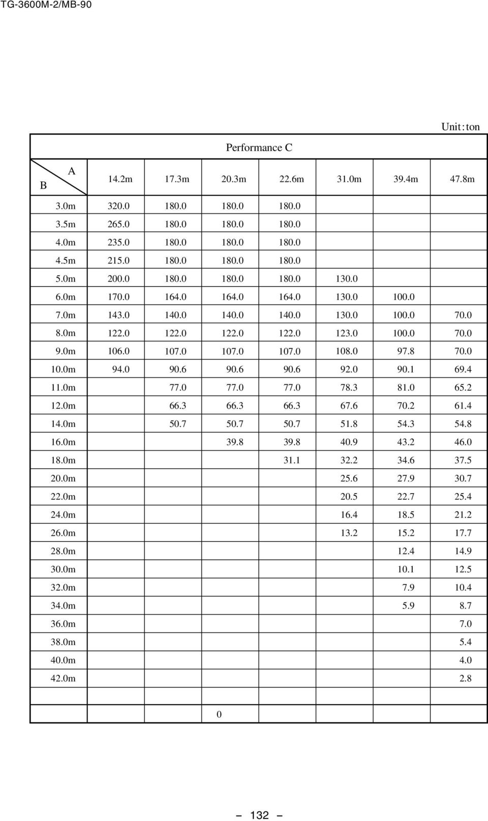
10 TG-00M-2/MB-90 [BOOM] (Stroke: 8.4m) B Performance C.2m 17.3m.3m.6m 31.0m 39.4m 4m 3.0m 3.0 m m 23 m 21 m m m m m m m m m m m m m m m m.4.9.0m.1.5.0m m m.0m 5.4.0m 4m = Boom length B= Working radius = Boom angle range (for the unladen condition) - 1 -
11 TG-00M-2/MB-90 [BOOM] (Stroke: 8.4m) B Performance D.2m 17.3m.3m.6m 31.0m 39.4m 4m 3.0m 2.0 m 1.0 m m m m m m m m m m m m m m m m m m.0m = Boom length B= Working radius = Boom angle range (for the unladen condition)
 - 133 -")
12 [BOOM] (Stroke: 8.4m) Performance E B.2m 17.3m.3m.6m 31.0m 39.4m 4m 3.0m m m m m 6.0m m 8.0m 9.0m m 11.0m 1m.0m.0m.0m.0m Performance F B 3.0m m m m m 6.0m m 8.0m 9.0m m 11.0m.2m.6m = Boom length B= Working radius = Boom angle range (for the unladen condition) - 1 -
 - 1 -")
13 TG-00M-2/MB-90 [BOOM] (Stroke: 9.2m) B Performance S.2m 17.3m.3m 2m.6m 4m 51.0m 3.0m 0.0 m m 27 m m m m m m m m m m m m m m m m m m m 2.2.0m m m 1.1.0m 1 4m.0 4m m = Boom length B= Working radius = Boom angle range (for the unladen condition)
 - 135 -")
14 TG-00M-2/MB-90 [BOOM] (Stroke: 9.2m) B Performance.2m 17.3m.3m 2m.6m 4m 51.0m 3.0m 0.0 m 0.0 m 0.0 m 0.0 m m m m m m m m m m m m m m m m m.9 2.0m.2.2.0m.0.7.0m m 1.8.0m 1 4m 1 4m.6.0m = Boom length B= Working radius = Boom angle range (for the unladen condition) - 1 -

15 TG-00M-2/MB-90 [BOOM] (Stroke: 9.2m) B Performance B.2m 17.3m.3m 2m.6m 4m 51.0m 3.0m 0.0 m 0.0 m 0.0 m 0.0 m m m m m m m m m m m m m m m m m m.2.4.0m 1.2.0m.2.4.0m m 9.3 4m 4m.0m = Boom length B= Working radius = Boom angle range (for the unladen condition)

16 TG-00M-2/MB-90 [BOOM] (Stroke: 9.2m) B Performance C.2m 17.3m.3m 2m.6m 4m 51.0m 3.0m 3.0 m m 23 m 21 m m m m m m m m m m m m m m m m m m.4.0m m 6.9.0m 5.3.0m 4m = Boom length B= Working radius = Boom angle range (for the unladen condition) - 1 -
 - 1 -")
17 TG-00M-2/MB-90 [BOOM] (Stroke: 9.2m) B Performance D.2m 17.3m.3m 2m.6m 4m 51.0m 3.0m 2.0 m 1.0 m m m m m m m m m m m m m m m m m m.0m = Boom length B= Working radius = Boom angle range (for the unladen condition)
 - 139 -")
18 TG-00M-2/MB-90 [BOOM] (Stroke: 9.2m) Performance E B.2m 17.3m.3m 2m.6m 4m 51.0m 3.0m m m m m 6.0m m 8.0m 9.0m m 11.0m 1m.0m.0m.0m.0m B 3.0m m m m m 6.0m m 8.0m 9.0m m 11.0m Performance F.2m 2m B Performance G 3.0m m m m m 6.0m m 8.0m 9.0m m = Boom length B= Working radius = Boom angle range (for the unladen condition) m B Performance H 3.0m m m m m 6.0m m 8.0m 9.0m m.2m
 - 1 -.2m 23 83 B Performance H 3.0m m m m m 6.0m m 8.0m 9.0m m.2m 6.")
19 TG-00M-2/MB-90 WORKING RDIUS - LIFTING HEIGHT BOOM (each section stroke: 8.4m) BOOM BOOM BOOM BOOM LIFTING HEIGHT (m) BOOM WORKING RDIUS (m) BOOM LIFTING HEIGHT (m) BOOM LIFTING HEIGHT (m) WORKING RDIUS (m) WORKING RDIUS (m) NOTES: 1. The deflection of the boom is not incorporated in the figure above. 2. The above charts show the maximum working radii of performance S, and B

20 TG-00M-2/MB-90 WORKING RDIUS - LIFTING HEIGHT BOOM (each section stroke: 9.2m) BOOM BOOM BOOM BOOM LIFTING HEIGHT (m) BOOM WORKING RDIUS (m) BOOM LIFTING HEIGHT (m) BOOM LIFTING HEIGHT (m) WORKING RDIUS (m) WORKING RDIUS (m) NOTES: 1. The deflection of the boom is not incorporated in the figure above. 2. The above charts show the maximum working radii of performance S, and B

21 TG-00M-2/MB-90 DIMENSIONS (1/0) [On-site traveling condition] - 3 -
22 M E M O - 4 -
23 TRUCK CRNE TG-00M JPNESE SPECIFICTIONS TG These specifications are for the optional fully automatic luffing jib for the TG-00M type crane. Refer to these specifications along with specification control no. TG-00M-2/MB-80. Control No. TG-00M-2/FLJ Return to INDEX
24 TG-00M-2/FLJ-80 TG-00M CRNE SPECIFICTIONS CRNE CPCITY 11.1m Jib 54,000kg at m ( 5part-line) 19.1m Jib 29,000kg at 8.0m ( 3part-line) 27.1m Jib,000kg at.0m ( 1part-line) 35.1m Jib 9,0kg at.0m ( 1part-line) Jib 4-section hydraulically telescoping boom of hexagonal box construction (stage 2: sequential; stages 3,4: synchronized) Hydraulic non-stage offset (0 - ) type m (fixed part) m m (elevating/telescoping part) JIB LENGTH 11.1m 19.1m 27.1m 35.1m MX.LIFTING HEIGHT 88.0m MX.WORKING RDIUS 70.0m - 6 -
25 TG-00M-2/FLJ-80 TOTL RTED LODS 1. The total rated loads shown are for the case where the outriggers are set horizontally on firm level ground. The values above the bold lines are based on the crane strength while those below are based on the crane stability. 2. The weights of the slings and hooks are included in the total rated loads shown. 3. The total rated load is based on the actual working radius including the deflection of the boom and jib. 4. The chart below shows the standard hook and number of part lines under each working condition M H N O L 1,0 1, = Boom length (m) M= Max. total rated loads (t) H= No. of part-lines N= Hook lifting capacity (t) O= No. of sheaves L= Hook weight (kg) 5. Boom length and boom fixing pin The boom telescoping order, stroke of each boom, boom length, boom fixing pin condition when the boom and jib are used are as follows. 1) Boom telescoping order and stroke of each boom Extend the boom from the base boom side, and then extend the next boom when the boom is extended by the strokes shown in the following table. Retract the boom from the top boom side, and then retract the next boom when the boom is retracted by the strokes shown in the following table. Crane service condition Boom Fully automatic luffing jib Boom stroke 9.2m - 7 -
26 TG-00M-2/FLJ-80 2) Boom length and boom fixing pin status Boom length (m) Boom Fully automatic luffing jib Boom Luffing jib Pin condition when the boom fixing pin is used Pin inserted Pin removed Both pin insertion and removal are available When the boom is operated, when the boom is extended to the middle, and when at least one boom fixing pin condition marked with in the above chart is, the performance for the case where the boom fixing pin is not used shall apply. When operating the jib (fully automatic luffing jib, luffing jib), the boom length and the boom fixing pin condition must be in accordance with the above chart. 6. s shown in the following table, the performance depends on the outrigger installation condition and counterweight combination. Counterweight Outrigger extension width 85t 65t 45t t 8.8m m B C C D D Both of the front and rear jacks should be used. The boom fixing pin should be used. 7. Mark in the total rated load chart shows the boom angle range (under no load)
27 TG-00M-2/FLJ m Jib B= Working radius D= Jib offset = Boom angle range (for the unladen condition) 8 9 [.2m Boom + m + Fully automatic luffing jib] Performance 19.1m Jib m Jib m Jib
28 TG-00M-2/FLJ m Jib B= Working radius D= Jib offset = Boom angle range (for the unladen condition) 8 9 [2m Boom + m + Fully automatic luffing jib] Performance 19.1m Jib m Jib m Jib
29 TG-00M-2/FLJ m Jib B= Working radius D= Jib offset = Boom angle range (for the unladen condition) [.6m Boom + m + Fully automatic luffing jib] Performance 19.1m Jib m Jib m Jib
30 TG-00M-2/FLJ m Jib B= Working radius D= Jib offset = Boom angle range (for the unladen condition) [4m Boom + m + Fully automatic luffing jib] Performance 19.1m Jib m Jib m Jib
31 TG-00M-2/FLJ m Jib B= Working radius D= Jib offset = Boom angle range (for the unladen condition) [51.0m Boom + m + Fully automatic luffing jib] Performance 19.1m Jib m Jib m Jib
32 TG-00M-2/FLJ m Jib B= Working radius D= Jib offset = Boom angle range (for the unladen condition) 8 9 [.2m Boom + m + Fully automatic luffing jib] Performance B 19.1m Jib m Jib m Jib
33 TG-00M-2/FLJ m Jib B= Working radius D= Jib offset = Boom angle range (for the unladen condition) 8 9 [2m Boom + m + Fully automatic luffing jib] Performance B 19.1m Jib m Jib m Jib
34 TG-00M-2/FLJ m Jib B= Working radius D= Jib offset = Boom angle range (for the unladen condition) [.6m Boom + m + Fully automatic luffing jib] Performance B 19.1m Jib m Jib m Jib
35 TG-00M-2/FLJ m Jib B= Working radius D= Jib offset = Boom angle range (for the unladen condition) [4m Boom + m + Fully automatic luffing jib] Performance B 19.1m Jib m Jib m Jib
36 TG-00M-2/FLJ m Jib B= Working radius D= Jib offset = Boom angle range (for the unladen condition) [51.0m Boom + m + Fully automatic luffing jib] Performance B 19.1m Jib m Jib m Jib
37 TG-00M-2/FLJ m Jib B= Working radius D= Jib offset = Boom angle range (for the unladen condition) 8 9 [.2m Boom + m + Fully automatic luffing jib] Performance C 19.1m Jib m Jib m Jib
38 TG-00M-2/FLJ m Jib B= Working radius D= Jib offset = Boom angle range (for the unladen condition) 8 9 [2m Boom + m + Fully automatic luffing jib] Performance C 19.1m Jib m Jib m Jib
39 TG-00M-2/FLJ m Jib B= Working radius D= Jib offset = Boom angle range (for the unladen condition) [.6m Boom + m + Fully automatic luffing jib] Performance C 19.1m Jib m Jib m Jib
40 TG-00M-2/FLJ m Jib B= Working radius D= Jib offset = Boom angle range (for the unladen condition) [4m Boom + m + Fully automatic luffing jib] Performance C 19.1m Jib m Jib m Jib
41 TG-00M-2/FLJ m Jib B= Working radius D= Jib offset = Boom angle range (for the unladen condition) [51.0m Boom + m + Fully automatic luffing jib] Performance C 19.1m Jib m Jib m Jib
42 TG-00M-2/FLJ m Jib B= Working radius D= Jib offset = Boom angle range (for the unladen condition) 8 9 [.2m Boom + m + Fully automatic luffing jib] Performance D 19.1m Jib m Jib m Jib
43 TG-00M-2/FLJ m Jib B= Working radius D= Jib offset = Boom angle range (for the unladen condition) 8 9 [2m Boom + m + Fully automatic luffing jib] Performance D 19.1m Jib m Jib m Jib
44 TG-00M-2/FLJ m Jib B= Working radius D= Jib offset = Boom angle range (for the unladen condition) [.6m Boom + m + Fully automatic luffing jib] Performance D 19.1m Jib m Jib m Jib
45 TG-00M-2/FLJ m Jib B= Working radius D= Jib offset = Boom angle range (for the unladen condition) [4m Boom + m + Fully automatic luffing jib] Performance D 19.1m Jib m Jib m Jib
46 TG-00M-2/FLJ m Jib B= Working radius D= Jib offset = Boom angle range (for the unladen condition) [51.0m Boom + m + Fully automatic luffing jib] Performance D 19.1m Jib m Jib m Jib
47 TG-00M-2/FLJ-80 WORKING RDIUS - LIFTING HEIGHT [.2m Boom + m + Fully automatic luffing jib] LIFTING HEIGHT (m) WORKING RDIUS (m) NOTES: 1. The deflection of the boom is not incorporated in the figure above. 2. The above chart is for Performance
48 TG-00M-2/FLJ-80 [2m Boom + m + Fully automatic luffing jib] LIFTING HEIGHT (m) WORKING RDIUS (m) NOTES: 1. The deflection of the boom is not incorporated in the figure above. 2. The above chart is for Performance
49 TG-00M-2/FLJ-80 [.6m Boom + m + Fully automatic luffing jib] LIFTING HEIGHT (m) WORKING RDIUS (m) NOTES: 1. The deflection of the boom is not incorporated in the figure above. 2. The above chart is for Performance
50 TG-00M-2/FLJ-80 [4m Boom + m + Fully automatic luffing jib] LIFTING HEIGHT (m) WORKING RDIUS (m) NOTES: 1. The deflection of the boom is not incorporated in the figure above. 2. The above chart is for Performance
51 TG-00M-2/FLJ-80 [51.0m Boom + m + Fully automatic luffing jib] LIFTING HEIGHT (m) WORKING RDIUS (m) NOTES: 1. The deflection of the boom is not incorporated in the figure above. 2. The above chart is for Performance
52 MEMO
53 TRUCK CRNE TG-00M JPNESE SPECIFICTIONS TG These specifications are for the optional luffing jib for the TG-00M type crane. Refer to these specifications along with specification control no. TG-00M-2/MB-80. Control No. TG-00M-2/LJ Return to INDEX
54 TG-00M-2/LJ-80 TG-00M CRNE SPECIFICTIONS CRNE CPCITY 17m Jib 0,000kg at m ( 9part-line) 23m Jib 80,000kg at 1m ( 8part-line) 35m Jib 51,0kg at.0m ( 6part-line) 47m Jib 31,000kg at.0m ( 4part-line) *65m Jib 8,000kg at 3m ( 1part-line) *70m Jib 5,000kg at 5m ( 1part-line) For the mark *, luffing jib (47m) + extension jib Jib Lattice type JIB LENGTH m (fixed part) + 1m, 23.0m, 3m, 4m, *6m, *70.0m (elevating part) For the mark *, luffing jib (47m) + extension jib MX.LIFTING HEIGHT 98.0m (t) 119.0m (t) (luffing jib + extension jib) MX.WORKING RDIUS 70.0m (t) 90.0m (t) (luffing jib + extension jib)
55 TG-00M-2/LJ-80 TOTL RTED LODS 1. The total rated loads shown are for the case where the outriggers are set horizontally on firm level ground. The values above the bold lines are based on the crane strength while those below are based on the crane stability. 2. The weights of the slings and hooks are included in the total rated loads shown. 3. The total rated load is based on the actual working radius including the deflection of the boom and jib. 4. The chart below shows the standard hook and number of part lines under each working condition..2m Boom.6m Boom 31.0m Boom 39.4m Boom 4m Boom Jib length (m) M H N L M H N L M H N L M H N L M H N L (4) 0 2, (3) 0 2,0 5 6(2) 80 1, (2) 80 1, (4) 6(3) 4(2) 4(2) ,0 1,0 1,0 1, (4) 4(3) 4(2) 2(2) ,0 1,0 1, (2) 2(2) (2) 2(2) M= Max. total rated loads (t) H= No. of part-lines N= Hook lifting capacity (t) L= Hook weight (kg) To prevent the jib from toppling over in the over-rear area, operations should be performed with the minimum number of part lines in parentheses or more even if the load is small. 5. Boom length and boom fixing pin The boom telescoping order, stroke of each boom, boom length, boom fixing pin condition when the boom and jib are used are as follows. 1) Boom telescoping order and stroke of each boom Extend the boom from the base boom side, and then extend the next boom when the boom is extended by the strokes shown in the following table. Retract the boom from the top boom side, and then retract the next boom when the boom is retracted by the strokes shown in the following table. Crane service condition Luffing jib Boom stroke 8.4m
56 TG-00M-2/LJ-80 2) Boom length and boom fixing pin status Boom length (m) Boom Boom Fully Luffing automatic jib luffing jib Pin condition when the boom fixing pin is used Pin inserted Pin removed Both pin insertion and removal are available When the boom is operated, when the boom is extended to the middle, and when at least one boom fixing pin condition marked with in the above chart is, the performance for the case where the boom fixing pin is not used shall apply. When operating the jib (fully automatic luffing jib, luffing jib), the boom length and the boom fixing pin condition must be in accordance with the above chart. 6. s shown in the following table, the performance depends on the outrigger installation condition and counterweight combination. Counterweight Outrigger extension width 8.8m 0t Both of the front and rear jacks should be used. The boom fixing pin should be used. S 85t 65t B
57 TG-00M-2/LJ-80 [m + 17m Luffing jib] Performance S.2m.6m 31.0m E( ) B(m) = Boom length B= Working radius E= Boom angle
58 TG-00M-2/LJ-80 [m + 23m Luffing jib] Performance S.2m.6m 31.0m E( ) B(m) = Boom length B= Working radius E= Boom angle
59 - 1 - TG-00M-2/LJ-80.2m.6m 31.0m B(m) E( ) = Boom length B= Working radius E= Boom angle [m + 35m Luffing jib] Performance S
60 TG-00M-2/LJ-80 [m + 35m Luffing jib] Performance S 39.4m 4m E ( ) B(m) = Boom length B= Working radius E= Boom angle
61 - 3 - TG-00M-2/LJ-80.2m.6m 31.0m B(m) E( ) = Boom length B= Working radius E= Boom angle [m + 47m Luffing jib] Performance S
62 TG-00M-2/LJ-80 [m + 47m Luffing jib] Performance S 39.4m 4m E( ) B(m) = Boom length B= Working radius E= Boom angle
63 TG-00M-2/LJ-80 [m + 47m Luffing jib + m Extension jib] Performance S 31.0m 39.4m 4m E( ) B(m) = Boom length B= Working radius E= Boom angle
64 TG-00M-2/LJ-80 [m + 47m Luffing jib + 23m Extension jib] Performance S 31.0m 39.4m 4m E( ) B(m) = Boom length B= Working radius E= Boom angle
65 TG-00M-2/LJ-80 [m + 17m Luffing jib] Performance.2m.6m 31.0m E( ) B(m) = Boom length B= Working radius E= Boom angle
66 TG-00M-2/LJ-80 [m + 23m Luffing jib] Performance.2m.6m 31.0m E( ) B(m) = Boom length B= Working radius E= Boom angle
67 .2m.6m 31.0m B(m) E( ) = Boom length B= Working radius E= Boom angle TG-00M-2/LJ-80 [m + 35m Luffing jib] Performance
68 TG-00M-2/LJ-80 [m + 35m Luffing jib] Performance 39.4m 4m E( ) B(m) = Boom length B= Working radius E= Boom angle
69 TG-00M-2/LJ-80.2m.6m 31.0m B(m) E( ) = Boom length B= Working radius E= Boom angle [m + 47m Luffing jib] Performance
70 TG-00M-2/LJ-80 [m + 47m Luffing jib] Performance 39.4m 4m E( ) B(m) = Boom length B= Working radius E= Boom angle
71 TG-00M-2/LJ-80 [m + 47m Luffing jib + m Extension jib] Performance 31.0m 39.4m 4m E( ) B(m) = Boom length B= Working radius E= Boom angle
72 TG-00M-2/LJ-80 [m + 47m Luffing jib + 23m Extension jib] Performance 31.0m 39.4m 4m E( ) B(m) = Boom length B= Working radius E= Boom angle
73 TG-00M-2/LJ-80 [m + 17m Luffing jib] Performance B.2m.6m 31.0m E( ) B(m) = Boom length B= Working radius E= Boom angle
74 TG-00M-2/LJ-80 [m + 23m Luffing jib] Performance B.2m.6m 31.0m E( ) B(m) = Boom length B= Working radius E= Boom angle
75 TG-00M-2/LJ-80.2m.6m 31.0m B(m) E( ) = Boom length B= Working radius E= Boom angle [m + 35m Luffing jib] Performance B
76 TG-00M-2/LJ-80 [m + 35m Luffing jib] Performance B 39.4m 4m E( ) B(m) = Boom length B= Working radius E= Boom angle
77 TG-00M-2/LJ-80.2m.6m 31.0m B(m) E( ) = Boom length B= Working radius E= Boom angle [m + 47m Luffing jib] Performance B
GMK5250L Product Guide ASME B30.5 Imperial 85%
 GMK5250L Product Guide ASME B30.5 Imperial 85% Features 250 t (300 USt) capacity 70 m (230 ft) seven-section main boom 21 m (69 ft) swingaway with jib and/or boom inserts. Maximum 37 m (121 ft) length
π H-4710 ELECTRIC PALLET TRUCK LB uline.com
 -00-9-0 Steering arm DIAGRAM 0 0 7 7 0 7 9 9 0 9 PAGE OF 0 0 PH-70 -00-9-0 Steering arm parts list Control Head Assembly ---------- 0-0000-00 Steering Arm H-70STEER 0-0000-0A Gas Spring Assembly H-00 0-0000-00
NMBTC.COM /
 Common Common Vibration Test:... Conforms to JIS C 60068-2-6, Amplitude: 1.5mm, Frequency 10 to 55 Hz, 1 hour in each of the X, Y and Z directions. Shock Test:...Conforms to JIS C 60068-2-27, Acceleration
Smaller. 6.3 to 100 After 1 minute's application of rated voltage at 20 C, leakage current is. not more than 0.03CV or 4 (µa), whichever is greater.
, whichever is greater.") Low Impedance, For Switching Power Supplies Low impedance and high reliability withstanding 5000 hours load life at +05 C (3000 / 2000 hours for smaller case sizes as specified below). Capacitance ranges
Low Impedance, For Switching Power Supplies Low impedance and high reliability withstanding 5000 hours load life at +05 C (3000 / 2000 hours for smaller case sizes as specified below). Capacitance ranges
DX500LCA / DX520LCA-HD
 DX500LCA / DX520LCA-HD CONTENTS PAGE 1. GENERAL SPECIFICATION... 2 2. ENGINE SYSTEM... 3 3. HYDRAULIC SYSTEM... 3 4. SWING MECHANISM... 4 5. TRAVEL SYSTEM... 4 6. UNDERCARRIAGE... 4 7. HYDRAULIC CYLINDERS...
Surface Mount Multilayer Chip Capacitors for Commodity Solutions
 Surface Mount Multilayer Chip Capacitors for Commodity Solutions Below tables are test procedures and requirements unless specified in detail datasheet. 1) Visual and mechanical 2) Capacitance 3) Q/DF
Thin Film Chip Resistors
 FEATURES PRECISE TOLERANCE AND TEMPERATURE COEFFICIENT EIA STANDARD CASE SIZES (0201 ~ 2512) LOW NOISE, THIN FILM (NiCr) CONSTRUCTION REFLOW SOLDERABLE (Pb FREE TERMINATION FINISH) Type Size EIA PowerRating
Data sheet Thick Film Chip Resistor 5% - RS Series 0201/0402/0603/0805/1206
 Data sheet Thick Film Chip Resistor 5% - RS Series 0201/0402/0603/0805/1206 Scope -This specification applies to all sizes of rectangular-type fixed chip resistors with Ruthenium-base as material. Features
Siemens AG Rated current 1FK7 Compact synchronous motor Natural cooling. I rated 7.0 (15.4) 11.5 (25.4) (2.9) 3.3 (4.4)
 11.5 (25.4) (2.9) 3.3 (4.4)") Synchronous motors Siemens 2009 FK7 Compact motors Nural cooling Selection and ordering da Red speed Shaft height n red S P red ΔT=00 K rpm kw (P) Red power Stic torque M 0 ΔT=00 K Red torque ) M red ΔT=00
Synchronous motors Siemens 2009 FK7 Compact motors Nural cooling Selection and ordering da Red speed Shaft height n red S P red ΔT=00 K rpm kw (P) Red power Stic torque M 0 ΔT=00 K Red torque ) M red ΔT=00
ΚΥΠΡΙΑΚΗ ΕΤΑΙΡΕΙΑ ΠΛΗΡΟΦΟΡΙΚΗΣ CYPRUS COMPUTER SOCIETY ΠΑΓΚΥΠΡΙΟΣ ΜΑΘΗΤΙΚΟΣ ΔΙΑΓΩΝΙΣΜΟΣ ΠΛΗΡΟΦΟΡΙΚΗΣ 19/5/2007
 Οδηγίες: Να απαντηθούν όλες οι ερωτήσεις. Αν κάπου κάνετε κάποιες υποθέσεις να αναφερθούν στη σχετική ερώτηση. Όλα τα αρχεία που αναφέρονται στα προβλήματα βρίσκονται στον ίδιο φάκελο με το εκτελέσιμο
D36-42 D46-42 D50-42 MODEL DIESEL PILE HAMMER SPARE PARTS BOOK
 MODEL D36-42 D46-42 D50-42 DIESEL PILE HAMMER SPARE PARTS BOOK Corporate Office 7032 S. 196th Street Kent, WA, USA 98032 Tel: 1-800-248-8498 Tel: 1-253-872-0141 Fax: 1-253-872-8710 2 No. Parts-No. Description
Parts catalogue LAWN MOWER
 OREC ISSUED NO. GRH535PRO-3 Parts catalogue LAWN MOWER (EXPORT MODEL) GRH535PRO(2Action) MODEL GRH535PRO CODE 0276- CONTENTS Fig. 1 GEAR CASE -------------------------------------- 1 Fig. 2 GEAR CASE INSIDE,
MRL HYDRAULIC LIFTS TYPE:
 DRO MRL MRL HYDRAULIC LIFTS TYPE: HYD Version: 1.1 Date: 26/04/2012 Page: 1/17 Range of Application 1 Version: 1.1 Date: 26/04/2012 Page: 2/17 Contents 3D LAYOUT... 3 TECHNICAL SPECIFICATION... 4 ACTING
NPI Unshielded Power Inductors
 FEATURES NON-SHIELDED MAGNETIC CIRCUIT DESIGN SMALL SIZE WITH CURRENT RATINGS TO 16.5 AMPS SURFACE MOUNTABLE CONSTRUCTION TAKES UP LESS PCB REAL ESTATE AND SAVES MORE POWER TAPED AND REELED FOR AUTOMATIC
UDZ Swirl diffuser. Product facts. Quick-selection. Swirl diffuser UDZ. Product code example:
 UDZ Swirl diffuser Swirl diffuser UDZ, which is intended for installation in a ventilation duct, can be used in premises with a large volume, for example factory premises, storage areas, superstores, halls,
MODEL D62-42 D70-42 DIESEL PILE HAMMER SPARE PARTS BOOK
 MODEL D62-42 D70-42 DIESEL PILE HAMMER SPARE PARTS BOOK Corporate Office 7032 S. 196th Street Kent, WA, USA 98032 Tel: 1-800-248-8498 Tel: 1-253-872-0141 Fax: 1-253-872-8710 2 No. Parts-No. Description
Parts catalogue LAWN MOWER
 OREC ISSUED NO. GR535PRO-1 Parts catalogue LAWN MOWER (EXPORT MODEL) GR535PRO(2Action) MODEL GR535PRO CODE 0278- CONTENTS Fig.1 GEAR CASE------------------------------------------------------------ 1 Fig.2
ROTARY TABLE SELECTION GUIDE
 ROTARY TABE SEECTION GUIDE 20 Thompson Rd East indsor CT 06088 1.800.249.5662 860.623.4132 ax www.komaprecision.com info@komaprecision.com ROTARY TABES RNE-SERIES RA-SERIES RBS-SERIES RN-MUTI SERIES (SHON
LS series ALUMINUM ELECTROLYTIC CAPACITORS CAT.8100D. Specifications. Drawing. Type numbering system ( Example : 200V 390µF)
") Snap-in Terminal Type, 85 C Standard Withstanding 3000 hours application of rated ripple current at 85 C. Compliant to the RoHS directive (2011/65/EU). LS Smaller LG Specifications Item Category Temperature
Snap-in Terminal Type, 85 C Standard Withstanding 3000 hours application of rated ripple current at 85 C. Compliant to the RoHS directive (2011/65/EU). LS Smaller LG Specifications Item Category Temperature
10/15/2008 TX65. Baja Motorsports Inc. P.O. Box Phoenix, AZ Toll Free: PARTS AND PRICES ARE SUBJECT TO CHANGE 1 of 34
 TX65 Toll Free: 888-863-2252 PARTS AND PRICES ARE SUBJECT TO CHANGE 1 of 34 ENGINE Part UPC Number Description Baja Description 1 165-043 883099011399 ENGINE ENGINE,RED 1 1 $204.00 $153.00 1 65-043 883099011405
HΛΕΚΤΡΙΚΟΣ ΙΑ ΡΟΜΟΣ UPOWER 202
 HΛΕΚΤΡΙΚΟΣ ΙΑ ΡΟΜΟΣ UPOWER 202 Ευχαριστούµε που διαλέξατε τα όργανα γυµναστικής µας. Για καλύτερα αποτελέσµατα και για αποφυγή τραυµατισµών, πάντα να κάνετε ασκήσεις προθέρµανσης πριν χρησιµοποιήσετε τον
Multilayer Ceramic Chip Capacitors
 FEATURES X7R, X6S, X5R AND Y5V DIELECTRICS HIGH CAPACITANCE DENSITY ULTRA LOW ESR & ESL EXCELLENT MECHANICAL STRENGTH NICKEL BARRIER TERMINATIONS RoHS COMPLIANT SAC SOLDER COMPATIBLE* PART NUMBER SYSTEM
ECOL Motors In Aluminum Housing
 ECOL Motors In Aluminum Housing FEATURES APPLICATIONS E TBS C TBW B L K AC TBH A AA KK H AD N T E TBS R TBW L AC M 56-160 IM B3 56-160 IM B5 56-160 IM B14 TBH 4-S KK P HD N TBS T E R TBW L AC P M TBH 4-S
MODEL D25-42 D30-42 DIESEL PILE HAMMER SPARE PARTS BOOK
 MODEL D25-42 D30-42 DIESEL PILE HAMMER SPARE PARTS BOOK Corporate Office 7032 S. 196th Street Kent, WA, USA 98032 Tel: 1-800-248-8498 Tel: 1-253-872-0141 Fax: 1-253-872-8710 2 No. Parts-No. Description
RSDW08 & RDDW08 series
 /,, MODEL SELECTION TABLE INPUT ORDER NO. INPUT VOLTAGE (RANGE) NO LOAD INPUT CURRENT FULL LOAD VOLTAGE CURRENT EFFICIENCY (Typ.) CAPACITOR LOAD (MAX.) RSDW08F-03 344mA 3.3V 2000mA 80% 2000μF RSDW08F-05
KE434C Electronic lockstitch pattern tacker. 20,000 stitches (including 10,000 stitches which can be added.)
") KE-434C Electronic Lockstitch Pattern Tacker KE-435C Electronic Lockstitch Pattern Tacker with Stepping Foot KE-434C-X KE-435C 1 Medium-weight 2 Heavy-weight Specifications Stitch formation Max. sewing
KE-434C Electronic Lockstitch Pattern Tacker KE-435C Electronic Lockstitch Pattern Tacker with Stepping Foot KE-434C-X KE-435C 1 Medium-weight 2 Heavy-weight Specifications Stitch formation Max. sewing
SPARE PARTS LIST. for. Infrared oil heater. Model. Daystar. Type. PH5 for 120V 60Hz. May, 2017
 SPARE PARTS LIST for Infrared oil heater Model Daystar Type PH5 for 120V 60Hz May, 2017 *PRICES AND SPECIFICATIONS ARE SUBJECT TO CHANGE WITHOUT NOTICE..* 2017 J.S.O'will, Inc.. Shizuoka Seiki Co. Ltd.
Operating Temperature Range ( C) ±1% (F) ± ~ 1M E-24 NRC /20 (0.05) W 25V 50V ±5% (J) Resistance Tolerance (Code)
 ±1% (F) ± ~ 1M E-24 NRC /20 (0.05) W 25V 50V ±5% (J) Resistance Tolerance (Code)") FEATURES EIA STANDARD SIZING 0201(1/20), 0402(1/16), 0603(1/10), 0805(1/8), 1206(1/4), 1210(1/3), 2010(3/4) AND 2512(1) METAL GLAZED THICK FILM ON HIGH PURITY ALUMINA SUBSTRATE..(CERMET) PROVIDES UNIFORM
FEATURES EIA STANDARD SIZING 0201(1/20), 0402(1/16), 0603(1/10), 0805(1/8), 1206(1/4), 1210(1/3), 2010(3/4) AND 2512(1) METAL GLAZED THICK FILM ON HIGH PURITY ALUMINA SUBSTRATE..(CERMET) PROVIDES UNIFORM
Math 6 SL Probability Distributions Practice Test Mark Scheme
 Math 6 SL Probability Distributions Practice Test Mark Scheme. (a) Note: Award A for vertical line to right of mean, A for shading to right of their vertical line. AA N (b) evidence of recognizing symmetry
65W PWM Output LED Driver. IDLV-65 series. File Name:IDLV-65-SPEC
 ~ A File Name:IDLV65SPEC 07050 SPECIFICATION MODEL OUTPUT OTHERS NOTE DC VOLTAGE RATED CURRENT RATED POWER DIMMING RANGE VOLTAGE TOLERANCE PWM FREQUENCY (Typ.) SETUP TIME Note. AUXILIARY DC OUTPUT Note.
Digital motor protection relays
 Digital motor protection relays Specification DMP -S & DMP -Sa DMP -T & DMP -Ta Model No. DMP06-S/Sa DMP60-S/Sa DMP06-T/Ta DMP60-T/Ta Wiring Screw type Tunnel type Panel mount Unit or Extension Note1)
RECIPROCATING COMPRESSOR CALCULATION SHEET
 Gas properties, flowrate and conditions 1 Gas name Air RECIPRCATING CMPRESSR CALCULATIN SHEET WITH INTERCLER ( Sheet : 1. f 4.) Item or symbol Quantity Unit Item or symbol Quantity Unit 2 Suction pressure,
1000 VDC 1250 VDC 125 VAC 250 VAC J K 125 VAC, 250 VAC
 Metallized Polyester Film Capacitor Type: ECQE(F) Non-inductive construction using metallized Polyester film with flame retardant epoxy resin coating Features Self-healing property Excellent electrical
CSR series. Thick Film Chip Resistor Current Sensing Type FEATURE PART NUMBERING SYSTEM ELECTRICAL CHARACTERISTICS
 FEATURE Operating Temperature: -55 ~ +155 C 3 Watts power rating in 1 Watt size, 1225 package High purity alumina substrate for high power dissipation Long side terminations with higher power rating PART
MRL HYDRAULIC LIFTS TYPE:
 Page: 1/18 Range of Application Page: 2/18 Contents 3D LAYOUT... 3 TECHNICAL SPECIFICATION... 4 ACTING 2:1... 4 LAYOUT ARRANGEMENT: ACTING 2:1... 5 SINGLE ENTRANCE GUIDE RAILS AT THE SIDE... 5 Plan view...
Multilayer Ceramic Chip Capacitors
 FEATURES X7R, X6S, X5R AND Y5V DIELECTRICS HIGH CAPACITANCE DENSITY ULTRA LOW ESR & ESL EXCELLENT MECHANICAL STRENGTH NICKEL BARRIER TERMINATIONS RoHS COMPLIANT SAC SOLDER COMPATIBLE* Temperature Coefficient
38BXCS STANDARD RACK MODEL. DCS Input/Output Relay Card Series MODEL & SUFFIX CODE SELECTION 38BXCS INSTALLATION ORDERING INFORMATION RELATED PRODUCTS
 DCS Input/Output Relay Card Series STANDARD RACK MODEL 38BXCS MODEL & SUFFIX CODE SELECTION 38BXCS MODEL CONNECTOR Y1 :Yokogawa KS2 cable use Y2 :Yokogawa KS9 cable use Y6 :Yokogawa FA-M3/F3XD32-3N use
- 1 - (FRAME PARTS ONLY)
") - 1 - (FRAME PARTS ONLY) - 2 - FIG 17 FRAME GROUP - 3 - NO. PART NO. DESCRIPTION QTY 1 8070054150GH00 ROLL CAGE FRONT 2 2 6010061150GH00 TOP CAGE 1 3 8010047250G000 R-WASHER 30 4 57870805512505 GB5787
- 1 - (FRAME PARTS ONLY) - 2 - FIG 17 FRAME GROUP - 3 - NO. PART NO. DESCRIPTION QTY 1 8070054150GH00 ROLL CAGE FRONT 2 2 6010061150GH00 TOP CAGE 1 3 8010047250G000 R-WASHER 30 4 57870805512505 GB5787
MSN DESK TOP ENCLOSURE WITH STAND / CARRYING HANDLE
 MSN SERIES MSN DESK TOP ENCLOSURE WITH STAND / CARRYING HANDLE W H FEATURE Available in 176 sizes. Stand / carrying handle can be adjusted in 30 degree. Maximum load is kg. There are no ventilation hole
Thick Film Chip Resistors
 FEATURES STANDARD SIZING 0402 (1/16W), 0603 (1/10W), 0805 (1/8W), 1206 (1/4W), 2010 (1/2W) AND 2512 (1W) HIGH VOLTAGE (100VDC ~ 3,000VDC) HIGH RESISTANCE VALUES (UP TO 100MW) THICK FILM ON ALUMINA SUSTRATE,
π H-2302 ELECTRIC PALLET TRUCK uline.com FORK FRAME
 FORK FRAME 1 1 3 4 5 6 16 19 1 18 0 3 6 4 13 14 5 7 8 7 9 10 PAGE 1 OF 10 FORK FRAME PARTS LIST 1 Fork Frame 1 ----------- 1000501004 Rock - Arm 1 ----------- 1000501014 3 Bushing ----------- 000007006
Thin Film Chip Resistors
 FETURES PRECISE TOLERNCE ND TEMPERTURE COEFFICIENT EI STNDRD CSE SIZES (0201 ~ 2512) LOW NOISE, THIN FILM (NiCr) CONSTRUCTION REFLOW SOLDERLE (Pb FREE TERMINTION FINISH) Type EI Size Power Rating at 70
500HSF. CYLINDER HEAD No. Part No. Description Q TY
 500HSF CYLINDER HEAD No. Part No. Description Q TY 1 12200-F18-0000 Cylinder Head Comp(EFI Engine) 1 2 91201-F11-0000 O-Ring 58 2.4 2 3 12361-F11-0000 Value Cover 2 4 70.1-6-20 Inner Hexangular Screw M6
Thin Film Chip Resistors
 FETURES PRECISE TOLERNCE ND TEMPERTURE COEFFICIENT EI STNDRD CSE SIZES (0201 ~ 2512) LOW NOISE, THIN FILM (NiCr) CONSTRUCTION REFLOW SOLDERLE (Pb FREE TERMINTION FINISH) RoHS Compliant includes all homogeneous
Lowara SPECIFICATIONS
 SH Series Centrifugal pumps entirely made of AISI 36 stainless steel according to EN 733 (ex DIN 24255). Designed to pump hot, cold and moderately aggressive liquids. Available versions: SHE Close-coupled
RANGE OF APPLICATION HYDRO TOTAL MRL. ver sion 3.1 / 26-04-2012. web: www.doppler.gr Email: info@doppler.gr
 RANGE OF APPLICATION HYDRO TOTAL MRL ver sion 3.1 / 26-04-2012 Factory Head Office Polykastro Industrial Park 61200 Polykastro, Greece Tel.: +30 23430 20140, 20150 Fax: +30 23430 23701 Athens Office-Showroom
MS SERIES MS DESK TOP ENCLOSURE APPLICATION EXAMPLE FEATURE. Measuring instruments. Power supply equipments
 MS SERIES MS DESK TOP ENCLOSURE FEATURE Available in 176 sizes. Screws are not appeared on the surface. Usable as rack mount case with optinal mounting bracket. There are no ventilation hole for cover
DOUBLE STAGE SCISSORS CAR LIFT TYPE:
 DOUBLE STAGE TYPE: DP-X1 Version: Page: 1.0 1/10 Date: 18.07.08 Range of Application Page: 2/10 Contents 3D LAYOUT... 3 TECHNICAL SPECIFICATION... 5 THROUGH CAR... 6 Plan view... 6 SINGLE ENTRANCE CAR...
No. Part No. Part name and Description Q'ty REMARK A-004C-0000 Cylinder Head Assy(EFI Engine) 1
 1") HS500ATV-4 2013 Cylinder head assembly No. Part No. Part name and Description Q'ty REMARK 1 1220A-004C-0000 Cylinder Head Assy(EFI Engine) 1 1220A-004-0000 Cylinder Head Assy(Carburetor Engine) 1 1 CYLINDER
HS500ATV-4 2013 Cylinder head assembly No. Part No. Part name and Description Q'ty REMARK 1 1220A-004C-0000 Cylinder Head Assy(EFI Engine) 1 1220A-004-0000 Cylinder Head Assy(Carburetor Engine) 1 1 CYLINDER
Contents MRL HYDRAULIC LIFTS TYPE: HYDRO TOTAL MRL. Version: 3.0 Page: 2/18 Date:
 Page: 2/18 Contents 3D LAYOUT... 3 TECHNICAL SPECIFICATION... 4 ACTING 2:1... 4 LAYOUT ARRANGEMENT: ACTING 2:1... 5 SINGLE ENTRANCE GUIDE RAILS AT THE SIDE... 5 Plan view... 5 SINGLE ENTRANCE GUIDE RAILS
High Frequency Chip Inductor / CF TYPE
 High Frequency Chip Inductor / CF TYPE.Features: 1.Closed magnetic circuit avoids crosstalk. 2.S.M.T. type. 3.Excellent solderability and heat resistance. 4.High realiability. 5.The products contain no
Dimensions in inches (mm)
") SGMH Dimensions in inches (mm) () 3-Bit Incremental Encoder, without Brake 30 (0.04hp), 50 (0.07hp), 00 (0.3hp) ENCODER CBE, Φ0.24 (Φ6) U20276.8 (300) ±.8 (30) MOTOR CBE, Φ0.28 (Φ7) U88 or U3535.38 (35)
SGMH Dimensions in inches (mm) () 3-Bit Incremental Encoder, without Brake 30 (0.04hp), 50 (0.07hp), 00 (0.3hp) ENCODER CBE, Φ0.24 (Φ6) U20276.8 (300) ±.8 (30) MOTOR CBE, Φ0.28 (Φ7) U88 or U3535.38 (35)
ED. 03/2017 ED. 07 /2008 PART CATALOGUE FM9SL SCISSOR LIFT
 ED. 03/2017 ED. 07 /2008 PART CATALOGUE FMSL SCISSOR LIFT TAV.0 LIFT 1 2 3 1 / TAV.0 LIFT ITEM PART NO. DESCRIPTION QTY REMARK 1 J32T010000 Runway P1 1 2 J32T020000 Runway P2 1 3 7335D03000 Control unit
HIS series. Signal Inductor Multilayer Ceramic Type FEATURE PART NUMBERING SYSTEM DIMENSIONS HIS R12 (1) (2) (3) (4)
 (2) (3) (4)") FEATURE High Self Resonant Frequency Superior temperature stability Monolithic structure for high reliability Applications: RF circuit in telecommunication PART NUMBERING SYSTEM HIS 160808 - R12 (1) (2)
FEATURE High Self Resonant Frequency Superior temperature stability Monolithic structure for high reliability Applications: RF circuit in telecommunication PART NUMBERING SYSTEM HIS 160808 - R12 (1) (2)
2 Composition. Invertible Mappings
 Arkansas Tech University MATH 4033: Elementary Modern Algebra Dr. Marcel B. Finan Composition. Invertible Mappings In this section we discuss two procedures for creating new mappings from old ones, namely,
DC-DC Constant Current Step-Down LED driver LDD-300L LDD-350L LDD-500L LDD-600L LDD-700L CURRENT RANGE
 SPECIFICATION ORDER NO. LDD-00L LDD-0L LDD-00L LDD-00L LDD-700L CURRENT RANGE 00mA 0mA 00mA VOLTAGE RANGE Note. ~ VDC for LDD-00~700L/LW ; ~ 8VDC for LDD-00~700LS CURRENT ACCURACY (Typ.) ±% at VDC input
Current Sensing Chip Resistor SMDL Series Size: 0201/0402/0603/0805/1206/1010/2010/2512/1225/3720/7520. official distributor of
 Product: Current Sensing Chip Resistor SMDL Series Size: 0201/0402/0603/0805/1206/1010/2010/2512/1225/3720/7520 official distributor of Current Sensing Chip Resistor (SMDL Series) 1. Features -3 Watts
Multilayer Chip Inductor
 Features -Monolithic structure for high reliability -High self-resonant frequency -Excellent solderability and high heat resistance Construction Applications -RF circuit in telecommunication and other
CSK series. Current Sensing Chip Resistor. Features. Applications. Construction FAITHFUL LINK
 CSK series Current Sensing Chip Resistor Features» 3 Watts power rating in 1 Watt size, 1225 Package» Low TCR of ±100 PPM/ C» Resistance values from 1m to 1 ohm» High purity alumina substrate for high
Lowara APPLICATIONS MATERIALS. General Catalogue
 FH Series Centrifugal electric pumps according to EN 733 (ex DIN 24255). Electric pumps with pump casing in cast iron and impeller in AISI 36* stainless steel, designed to pump hot, cold and moderately
ΕΙΣΑΓΩΓΗ ΣΤΗ ΣΤΑΤΙΣΤΙΚΗ ΑΝΑΛΥΣΗ
 ΕΙΣΑΓΩΓΗ ΣΤΗ ΣΤΑΤΙΣΤΙΚΗ ΑΝΑΛΥΣΗ ΕΛΕΝΑ ΦΛΟΚΑ Επίκουρος Καθηγήτρια Τµήµα Φυσικής, Τοµέας Φυσικής Περιβάλλοντος- Μετεωρολογίας ΓΕΝΙΚΟΙ ΟΡΙΣΜΟΙ Πληθυσµός Σύνολο ατόµων ή αντικειµένων στα οποία αναφέρονται
Tabela 1. Table 1 working slat. Spare parts. Rear-attached disc mower Z108/8 2,5m with swath spreader
 1 2 12 2 1 2 1 1 2 21 2 2 2 0 2 11 2 1 1 2 2 1 1 1 Tabela 1 Table 1 working slat Table 1 Cat. No. or Standard Qty No. Part name Z/ 2.m Z/ Working slat set. Contains: tab.1. pos.: 1- /1-000 tab.2. pos.:
RC series Thick Film Chip Resistor
 RC series Thick Film Chip Resistor Features» Small size and light weight» Compatible with wave and reflow soldering» Suitable for lead free soldering» RoHS compliant & Halogen Free Applications Configuration»
(REV:01) RYOBI 48 Volt Lawn Mower Model No. RY14110 Replacement Parts List
 RYOBI 48 Volt Lawn Mower Model No. RY14110 Replacement Parts List") 9800-86 2-0-0 (REV:0) RYOBI 48 Volt Lawn Mower Model No. RY0 Replacement Parts List RYOBI RY0 48 volt lawn mower 3 38 39 44 39 36 34 36 42 38 39 3 4 37 34 3 43 2 32 0 8 9 2 4 33 8 7 6 3 6 7 22 8 20 3 30
9800-86 2-0-0 (REV:0) RYOBI 48 Volt Lawn Mower Model No. RY0 Replacement Parts List RYOBI RY0 48 volt lawn mower 3 38 39 44 39 36 34 36 42 38 39 3 4 37 34 3 43 2 32 0 8 9 2 4 33 8 7 6 3 6 7 22 8 20 3 30
SPBW06 & DPBW06 series
 /,, MODEL SELECTION TABLE INPUT ORDER NO. INPUT VOLTAGE (RANGE) NO LOAD INPUT CURRENT FULL LOAD VOLTAGE CURRENT EFFICIENCY (TYP.) CAPACITOR LOAD (MAX.) SPBW06F-03 310mA 3.3V 0 ~ 1500mA 81% 4700μF SPBW06F-05
Item No. (English part name)
") E01 E01/CRANKCASE ASSY Part. (English part name) Design Change Effective date Interchan geability Remark 1 0800-013000 CVT ASSY 1 2 0800-013200 CVT CASE COVER ASSY 1 3 0800-013100 CVT CASE ASSY 1 4 0800-012000-0001
E01 E01/CRANKCASE ASSY Part. (English part name) Design Change Effective date Interchan geability Remark 1 0800-013000 CVT ASSY 1 2 0800-013200 CVT CASE COVER ASSY 1 3 0800-013100 CVT CASE ASSY 1 4 0800-012000-0001
Metal Oxide Leaded Film Resistor
 Features -Excellent Long-Time stability -High surge / overload capability -Wide resistance range : 0.1Ω~22MΩ -Controlled temperature coefficient -Resistance standard tolerance: ±5% (consult factory for
Territory 500cc Engine Parts Manual
 Territory 500cc Engine Parts Manual 1. CYLINDER HEAD 1 Cylinder Head Assy(EFI Engine) 1 Cylinder Head Assy(Carburetor Engine) 1 2. CYLINDER HEAD 1 12200-F18-0000 Cylinder Head Comp(EFI Engine) 1 2 91201-F11-0000
π H-3405 ELECTRIC PALLET TRUCK uline.com FORK FRAME
 FORK FRAME 17 18 1 4 24 25 26 22 26 3 23 5 19 23 6 20 21 2 9 4 27 28 7 8 4 5 15 8 16 6 7 14 10 12 11 13 11 PAGE 1 OF 12 FORK FRAME PARTS LIST 1 Fork Frame 1 ----------- 1060501011 2 Rock Arm 1 -----------
Westfalia Bedienungsanleitung. Nr
 Westfalia Bedienungsanleitung Nr. 108230 Erich Schäfer KG Tel. 02737/5010 Seite 1/8 RATED VALUES STARTING VALUES EFF 2 MOTOR OUTPUT SPEED CURRENT MOMENT CURRENT TORQUE TYPE I A / I N M A / M N Mk/ Mn %
(REV:01) RYOBI 48 Volt Lawn Mower Model No. RY14110A Replacement Parts List
 RYOBI 48 Volt Lawn Mower Model No. RY14110A Replacement Parts List") 9000-7 9-- (REV:0) RYOBI 4 Volt Lawn Mower Model No. RY0A Replacement Parts List RYOBI RY0A 4 VOLT LAWN MOWER 3 3 39 44 39 3 34 3 42 3 39 3 4 37 34 3 43 2 0 37 2 33 32 3 9 7 22 30 4 7 3 20 9 3 2 2 27 2
9000-7 9-- (REV:0) RYOBI 4 Volt Lawn Mower Model No. RY0A Replacement Parts List RYOBI RY0A 4 VOLT LAWN MOWER 3 3 39 44 39 3 34 3 42 3 39 3 4 37 34 3 43 2 0 37 2 33 32 3 9 7 22 30 4 7 3 20 9 3 2 2 27 2
ATLANTIS 150 ENGINE PARTS
 ATLANTIS 150 ENGINE PARTS E-1 CYLINDER HEAD COVER 1 12310-FYIQ2-000 COVER, CYLINDER HEAD 1 2 12312-FYDQ-000 OIL FENDER 1 3 GB/T845-ST4.2*8-A2G CROSS TAPPING BOLT M4*8 4 4 90103-06025-00F5J HEX. FLANGE
MATRIX. EBARA PUMPS EUROPE S.p.A. HORIZONTAL MULTISTAGE PUMPS
 CONTENTS Page - SPECIFICATIONS 200 PUMP SPECIFICATION 200 TYPE KEY 201 SELECTION CHART 202 SELECTION CHART 203 PERFORMANCE CURVE 3 ( 2-3-4-5 impellers ) 204 PERFORMANCE CURVE 3 ( 6-7-8-9 impellers ) 205
Finish: Anticorrosive finish in polyester. Number of motor poles 4=1400 r/min. 50 Hz 6=900 r/min. 50 Hz 8=750 r/min. 50 Hz
 HEP HEPT HEP: Wall-mounted axial fans, with IP65 motor HEPT: Long-cased axial fans, with IP65 motor Wall-mounted axial (HEP) and long-cased (HEPT) fans, with fibreglass-reinforced plastic impeller. Fan:
DLG Series. Lowara SPECIFICATIONS APPLICATIONS ACCESSORIES MATERIALS. General Catalogue
 DLG Series Submersible pumps with open impeller with grinder assembly for pumping sewage, liquids, wastewater in general and industrial sludge, draining of flooded excavations. SPECIFICATIONS Delivery:
PREMIER SERIES BY P1206RB-7
 PREMIER SERIES BY P1206RB-7 1. Casting Mechanism Line Part Number Description Qt. Notes 1 100 1001 Face plate 1 2 100 1002 Screw 2 3 100 1003 Thread guide 1 4 100 1004 Thread guide
π H-4709 BIG JOE ELECTRIC PALLET TRUCK uline.com STEERING ARM
 -00--0 STEERING ARM 0 0 PAGE OF -00--0 STEERING ARM PARTS LIST Screw, M x ---------- 0000-000-00 Lock Washer, M ---------- 0000-000-00 Screw, M x ---------- 0000-000-00 Plate ---------- -0000-00 Bracket
Thick Film Array Chip Resistor
 CN Series Scope -This specification applies to all sizes of rectangular-type fixed chip resistors with Ruthenium-base as material. Features -Small size and light weight -Reduction of assembly costs and
ED. 07/2010 ED. 07/2008 PART CATALOGUE TRUCK WHEEL BALANCER
 ED. 07/2010 ED. 07/2008 PART CATALOGUE TRUCK WHEEL BALANCER ELECTRIC PANEL TAV.1.0 WHEEL GUARD TAV.2.0 SHAFT ASSEMBLY TAV.3.0 BODY AND COVERS TAV.8.0 DRIVING/BRAKING MECHANISM TAV.4.0 DISTANCE GAUGE TAV.7.0
Approximation of distance between locations on earth given by latitude and longitude
 Approximation of distance between locations on earth given by latitude and longitude Jan Behrens 2012-12-31 In this paper we shall provide a method to approximate distances between two points on earth
ANSWERSHEET (TOPIC = DIFFERENTIAL CALCULUS) COLLECTION #2. h 0 h h 0 h h 0 ( ) g k = g 0 + g 1 + g g 2009 =?
 COLLECTION #2. h 0 h h 0 h h 0 ( ) g k = g 0 + g 1 + g g 2009 =?") Teko Classes IITJEE/AIEEE Maths by SUHAAG SIR, Bhopal, Ph (0755) 3 00 000 www.tekoclasses.com ANSWERSHEET (TOPIC DIFFERENTIAL CALCULUS) COLLECTION # Question Type A.Single Correct Type Q. (A) Sol least
Teko Classes IITJEE/AIEEE Maths by SUHAAG SIR, Bhopal, Ph (0755) 3 00 000 www.tekoclasses.com ANSWERSHEET (TOPIC DIFFERENTIAL CALCULUS) COLLECTION # Question Type A.Single Correct Type Q. (A) Sol least
Operating Instructions and Parts Manual Drum Sander Model PM2244
 Operating Instructions and Parts Manual Drum Sander Model PM2244 Powermatic 427 New Sanford Road LaVergne, Tennessee 37086 Part No. M-1792244 Ph.: 800-274-6848 Edition 1 08/2015 www.powermatic.com Copyright
4 Way Reversing Valve
 STANDARD 4 Way Reversing Valve SHF series four-way reversing valves are applicable for heat pump systems such as central, unitary and room air conditioners to realize switching between cooling mode and
Matrices and Determinants
 Matrices and Determinants SUBJECTIVE PROBLEMS: Q 1. For what value of k do the following system of equations possess a non-trivial (i.e., not all zero) solution over the set of rationals Q? x + ky + 3z
500UTV/500UTV-4(2013)
") 500UTV/500UTV-4(2013) CYLINDER HEAD 1 1220A-004C-0000 Cylinder Head Assy(EFI Engine) 1 1 CYLINDER HEAD 1 12200-004C-0000 Cylinder Head Comp(EFI Engine) 1 2 91205-002-0000 O-Ring 58 2.4 2 3 12361-004-0000
500UTV/500UTV-4(2013) CYLINDER HEAD 1 1220A-004C-0000 Cylinder Head Assy(EFI Engine) 1 1 CYLINDER HEAD 1 12200-004C-0000 Cylinder Head Comp(EFI Engine) 1 2 91205-002-0000 O-Ring 58 2.4 2 3 12361-004-0000
2011 Bearclaw 700 engine
 CYLINDER HEAD 1 12000-F39-0002 CYLINDER HEAD ASSY 1 2 899-8-45 STUD BOLT M8 45 4 3 12371-F39-0000 HAND HOLE COVER 1 4 91217-F39-0000 O-RING 13.4 2.35 1 5 90033-F39-0000 BOLT M9 109 4 6 90601-F39-0000 WASHER
Multilayer Chip Inductor / CL TYPE
 Multilayer Chip Inductor / CL TYPE.Features: 1.Closed magnetic circuit avoids crosstalk. 2.S.M.T. type. 3.Excellent solderability and heat resistance. 4.High realiability. 5.The products contain no lead
Surface Mount Aluminum Electrolytic Capacitors
 FEATURES CYLINDRICAL V-CHIP CONSTRUCTION LOW COST, GENERAL PURPOSE, 2000 HOURS AT 85 O C NEW EXPANDED CV RANGE (up to 6800µF) ANTI-SOLVENT (2 MINUTES) DESIGNED FOR AUTOMATIC MOUNTING AND REFLOW SOLDERING
Parts catalogue RABBIT MOWER RM86G(FB) (GXV390)
 (GXV390)") OREC ISSUED NO. -1 Parts catalogue RABBIT MOWER (EXPORT MODEL) (GXV390) MODEL CODE NO. 0240- CONTENTS Fig.1 FRAME & CONTROL------------------------------ 1 Fig.2 TRANSMISSION--------------------------------------
OREC ISSUED NO. -1 Parts catalogue RABBIT MOWER (EXPORT MODEL) (GXV390) MODEL CODE NO. 0240- CONTENTS Fig.1 FRAME & CONTROL------------------------------ 1 Fig.2 TRANSMISSION--------------------------------------
15W DIN Rail Type DC-DC Converter. DDR-15 series. File Name:DDR-15-SPEC
 DIN Rail Type DC-DC Converter ± : DIN Rail Type DC-DC Converter SPECIFICATION MODEL OUTPUT INPUT PROTECTION ENVIRONMENT SAFETY & EMC (Note 5) OTHERS DC VOLTAGE RATED CURRENT CURRENT RANGE RATED POWER RIPPLE
Strain gauge and rosettes
 Strain gauge and rosettes Introduction A strain gauge is a device which is used to measure strain (deformation) on an object subjected to forces. Strain can be measured using various types of devices classified
ΠΟΡΤΕΣ ΑΝΑΚΑΙΝΙΣΗΣ DOORS FOR MODERNIZATION
 ΠΟΡΤΕΣ ΑΝΑΚΑΙΝΙΣΗΣ DOORS FOR MODERNIZATION ΠΟΡΤΑ ΟΡΟΦΟΥ ΚΕΝΤΡΙΚΗ 2ΦΥΛΛΗ 2 PANELS CENTRE PARTING LANDING DOOR.1. Πόρτα ορόφου χωρίς κάσωμα, για ανακαινίσεις Landing door without frames, for modernization
ACTORS IEC CONT Ex9C
 IEC CONTCTORS Ex9C Ex9C Product Overview Features C-3 contactor ratings from 630 and C-1 contactor ratings to 800 voltages from 24~600, 50/60 Hz Full Non-Reversing (FVNR) and Full Reversing (FVR) 5 k @
the total number of electrons passing through the lamp.
 1. A 12 V 36 W lamp is lit to normal brightness using a 12 V car battery of negligible internal resistance. The lamp is switched on for one hour (3600 s). For the time of 1 hour, calculate (i) the energy
Fixed Inductors / AL TYPE
 .Features: 1.Coating epoxy resin that ensures the humidity resistance to be long life. 2.Contribute to be high Q and selfresonant frequencies.applications: 1.Electronics products. 2.Communication equipment.
Metal Film Leaded Precision Resistor
 Features Excellent overall stability Very tight tolerance down to ±0.05% Extremely low TCR down to ±5 PPM/ C High power rating up to 3 Watts Excellent ohmic contact Construction Applications Telecommunication
Polymer PTC Resettable Fuse: KRG Series
 Features 1. RoHS & Halogen-Free (HF) compliant 2. Radial leaded devices 3. Broadest range of resettable devices available in the industry 4. Hold current ratings from 0.1 to 3.75A 5. Maximum voltage is
Drum Head Assembly Exploded View
 Drum Head Assembly Exploded View 27 Drum Head Assembly Parts List 1...70-4102... Motor... 1-3/4HP, 115V... 1...70-4102MF... Motor Fan (not shown)...... 1...70-4102MFC... Motor Fan Cover (not shown)......
Fixed Inductors / AL TYPE
 .Features: 1.Coating epoxy resin that ensures the humidity resistance to be long life. 2.Contribute to be high Q and selfresonant frequencies.applications: 1.Electronics products. 2.Communication equipment.
DC-DC Constant Current Step-Down LED driver LDD-300L LDD-350L LDD-500L LDD-600L LDD-700L CURRENT RANGE
 SPECIFICATION ORDER NO. LDD-00L LDD-0L LDD-00L LDD-00L LDD-700L CURRENT RANGE 00mA 0mA 00mA 00mA VOLTAGE RANGE Note. ~ VDC for LDD-00~700L/LW ; ~ 8VDC for LDD-00~700LS CURRENT ACCURACY (Typ.) ±% at VDC