IAN BENCH PILLAR DRILL PTBM 500 D4. ΕΠΙΤΡΑΠΕΖΙΟ ΔΡΑΠΑΝΟ Μετάφραση των αυθεντικών οδηγιών λειτουργίας
|
|
|
- θάνατος Βαρουξής
- 7 χρόνια πριν
- Προβολές:
Transcript

1 BENCH PILLAR DRILL PTBM 500 D4 BENCH PILLAR DRILL Translation of the original instructions ΕΠΙΤΡΑΠΕΖΙΟ ΔΡΑΠΑΝΟ Μετάφραση των αυθεντικών οδηγιών λειτουργίας TISCHBOHRMASCHINE Originalbetriebsanleitung IAN
2 Before reading, unfold the page containing the illustrations and familiarise yourself with all functions of the device. Πριν ξεκινήσετε την ανάγνωση, ανοίξτε τη σελίδα με τις εικόνες και εξοικειωθείτε με όλες τις λειτουργίες της συσκευής. Klappen Sie vor dem Lesen die Seite mit den Abbildungen aus und machen Sie sich anschließend mit allen Funktionen des Gerätes vertraut. GB / IE / NI / CY Translation of the original instructions Page GR / CY Μετάφραση των αυθεντικών οδηγιών λειτουργίας Σελίδα DE / AT / CH Originalbetriebsanleitung Seite


3 A B 23 C


4 D E F
5 G B I E N I CY Content Introduction... 5 Intended purpose... 5 General description... 6 Extent of the delivery...6 Description of functions...6 Overview...6 Technical Data... 6 Notes on safety... 7 Symbols and icons...7 General notes on safety...8 General Safety Instructions for Power Tools...8 Assembly Operation Setting up...12 Selecting the speed...12 Checking the V-belts...13 Tensioning the V-belts...13 Adjusting the Drilling Bench...13 Preselecting the Drilling Depth...13 Changing the Bit...13 Drilling...14 General Information...14 Switching on and off...14 Clamping the Workpieces...14 Removing Blockages...14 Cleaning and maintenance Cleaning...15 Maintenance...15 Storage Troubleshooting Transport Waste disposal and environmental protection Replacement parts/accessories.. 17 Guarantee Repair Service Service-Center Importer Translation of the original EC declaration of conformity Exploded Drawing Introduction Congratulations on the purchase of your new device. With it, you have chosen a high quality product. During production, this equipment has been checked for quality and subjected your equipment is therefore guaranteed. It cannot be ruled out that residual quantities of water or lubricants will remain on or in the equipment/hose lines in isolated cases. This is not a fault or defect and it represents no cause for concern. The operating instructions constitute part of this product. They contain important information on safety, use and disposal. Before using the product, familiarise yourself with all of the operating and safety instructions. Use the product only as de- Keep this manual safely and in the event that the product is passed on, hand over all documents to the third party. Intended purpose The bench drill is designed for drilling in metal, wood, plastic and tiles. Straight shank drills with a drilling diameter from 1.5 mm to 16 mm can be used. The device is intended to be used by do-ityourselfers. It was not designed for heavy commercial use. The tool is not to be used by persons. under the age of 16. Children over the age of 16 may use the tool except under supervision. The manufacturer is not liable for damage caused by an improper use or incorrect operation of this device. 5
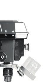
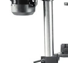
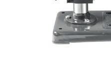
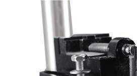
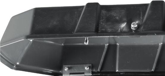
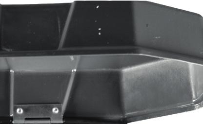
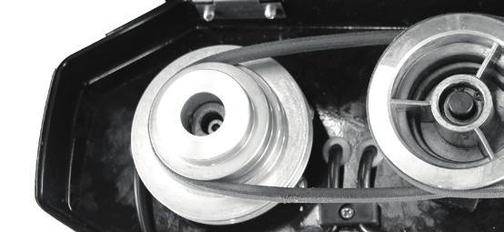
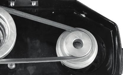
6 G B I E N I CY General description The illustration of the principal functioning parts can be found on the front and back foldout pages. Extent of the delivery Carefully unpack the appliance and check that it is complete. Dispose of the packaging material correctly. - Baseplate - Drilling bench - Column tube - Motor unit - 3 drill lifting arms - Safety device - Drill chuck - Drill chuck key - Allen key - Vice - Mounting material - Instruction Manual Description of functions Please refer to the descriptions below for information about the operating devices. Overview A 1 Off switch 2 On switch 3 Gear cover 4 Drill chuck 5 Emergency stop switch 6 Safety device 7 Drill spindle 8 Locking screw of the depth stop 9 Hand spindle guide with 3 drill lifting arms 10 Holder for drill chuck key E F 11 Locking screw for gear cover 12 Retaining screws for motor unit 13 Motor unit 14 Column tube 15 Locking handle 16 3 Assembly screws 17 Baseplate 18 Angle scaling 19 Retaining screw for drilling bench inclination 20 Drilling bench 21 Depth stop with scale 22 Vice mounting material 23 Vice 24 Chuck jaws 25 Allen key 26 Drill chuck key 27 Clamping screw for motor unit 28 Clamping screw for safety device 29 V-belt 30 Spindle-side drive pulley 31 Motor side drive pulley 32 Interlock switch Technical Data Bench Pillar Drill... PTBM 500 D4 Rated input voltage V~, 50 Hz Power input W (S2 15 min)* Idling speed (n 0 ) Spindle min -1 Motor min -1 Safety class... I Protection category...ipx0 Weight kg Drill chuck...b16 (1.5 mm to 16 mm) Spindle stroke...50 mm Workpiece size...max. 60 mm Sound pressure level (L pa ) db(a); K pa = 3 db 6
7 G B I E N I CY Sound power level (L WA ) measured db(a); K WA = 3 db guaranteed db(a) Vibration(a h )... 2,39 m/s 2 K= 1,5 m/s 2 * After continuous operation of 15 minutes the drill stops until the device temperature deviates by less than 2 K (2 C) from the room temperature. Levels of noise and vibration were determined according to the norms and regulations in the declaration of conformity. The vibration emission value has been measured according to a standardised testing method and may be used for comparison with another electric tool. The indicated vibration emission value may also be used for an introductory assessment of the exposure. Warning: The vibration emission value whilst actually using the electrical tool may vary from the given values independently of the type and way in which the electric tool is used. Try to keep the exposure to vibrations as low as possible. Examples of measures to reduce vibration exposure are the wearing of gloves when using the tool and limiting the working hours. For this purpose all parts of the operating cycle have to be considered (for example, times when the electric tool is switched off and times when it is switched on but running without any load). Notes on safety Caution! When using power tools, observe the following basic safety measures for the prevention of electric shocks and the risk of injury Please read all these instructions before using this electric tool and please keep the safety instructions. Symbols and icons Symbols on the device: Warning! Warning! Electric shock hazard. Always unplug the device before working on it. Read the manual! Wear ear protection Wear eye protection Do not wear long hair uncovered. Use a hair net. Do not wear gloves. Caution! Risk of injury from rotating parts! Caution! Hot surface. There is a risk of burns. Electrical machines do not belong with domestic waste 7
8 G B I E N I CY Symbols used in the instructions: Hazard symbols with information on prevention of personal injury and property damage. Precaution symbol with information on prevention of harm / damage. Connect the machine to the power supply. Pull out the mains plug. Notice symbol with information on how to handle the device properly. Steel Wood General notes on safety Caution! When using power tools, observe the following basic safety measures for the prevention of electric shocks and the risk of injury General Safety Instructions for Power Tools WARNING! Read all safety instructions and guidelines carefully. Failure to follow the safety instructions and guidelines may serious injuries. Save all safety instructions and guidelines for the future. The term power tool used in the safety instructions refers to mains-operated electric tools (with a mains cable) and to battery-operated electric tools (without a mains cable). Safe working Keep your work area tidy. An untidy workplace can lead to accidents. Consider environment influences - Do not expose power tools to rain. - Do not use power tools in damp or wet surroundings. - Ensure the work area is adequately lit. - Do not use power tools where there Protect yourself against electric shock. Avoid body contact with earthed parts (e.g. pipes, radiators, electric cookers, refrigerators). Keep other people away. Do not allow other people, especially children, to touch the power tool or cable. Keep them away from your work area. Store unused power tools safely. Unused power tools should be stored in a dry, high or locked place, out of the reach of children. Do not overload your power tool. They work better and more safely Use the correct power tool. - Do not use low-performance machines for heavy work. - Do not use the power tool for purposes for which it is not intended. For example, do not use use a circular hand saw for cutting tree branches or logs. Wear suitable clothing - Do not wear loose clothing or jewellery that might become caught in moving parts. - When working outdoors, non-slip footwear is recommended. - Wear a hair net to contain long hair. 8
9 G B I E N I CY Use protective equipment - - Wear safety goggles. - Use a dust mask for work which generates dust. Connect a dust extraction device. If connections are available for dust extraction and collection devices, make sure that these are connected and properly used. Do not use the cable for purposes for which it is not intended. Do not use the cable to pull the plug from the socket. Protect the cable from heat, oil and sharp edges. Secure the workpiece. Use jigs or a vice to hold the workpiece securely. This is safer than using your hand. Avoid abnormal body postures. Ensure secure footing and keep your balance at all times. Maintain tools with care - Keep cutting tools sharp and clean for better and safer working. - Follow the instructions for lubrication and changing tools. - Regularly check the connection cable of the power tool and, if it is dama- specialist. - Check extension cords periodically and replace them if they are damaged. - Keep handles dry, clean and free from oil and grease. Remove the plug from the mains socket when the power tool is not in use, before maintenance and when changing tools such as saw blades, drill bits, cutters. Do not allow any tool keys to remain inserted. Check, before switching on, that keys and adjusting tools have been removed. Avoid unintentional starting. Make sure that the switch is off when inserting the plug into the socket. Use extension cables outdoors. Only use approved and appropriately marked extension cables outdoors. Pay attention at all times. Pay attention to what you are doing. Work using common sense. Do not use the power tool if you cannot concentrate. Check the power tool for possible damage - Before further use of the power tool, safety devices or slightly damaged parts must be carefully examined in respect of their proper and intended function. - Check that the moving parts are working properly and are not jammed or whether parts are damaged. All satisfy all conditions to ensure the proper operation of the power tool. - Damaged safety equipment and parts must be repaired properly or replaced by an authorised specialist workshop unless otherwise indicated in the instructions. - Damaged switches must be replaced at a customer service workshop. - Do not use power tools if the switch cannot be turned on and off. CAUTION! The use of other bits and other accessories can result in a risk of personal injury. Have your power tool be repaired by a qualified electrician - This power tool complies with the relevant safety regulations. Repairs electrician, using original spare parts; otherwise accidents involving the user may result. 9
10 G B I E N I CY Service: Have your power tool repaired only by qualified specialists and only with original spare parts. This will ensure that the power tool remains safe. Safety Instructions for Box Column Drills Never make the warning labels on the power tool illegible. Attach the power tool to a solid, flat and horizontal surface. If the power tool can slip or wobble, the bit may not be guided smoothly and safely. Keep the work area clean except for the workpiece to be machined. Sharp-edged drilling chips and objects can cause injury. Material mixtures are particularly dangerous. Light metal dust can burn or explode. Set the correct speed before starting work. The speed must be appropriate for the drill diameter and the material to be drilled. At an incorrectly set speed the bit may get jammed in the workpiece. Only when the device is turned on should the bit be moved against the work piece. Otherwise there is a danger that the bit will get jammed in the workpiece and the workpiece will rotate with the bit. This can lead to injuries. Do not put your hands in the area of the drill while the power tool is running. Upon contact with the bit is a risk of injury. Never remove drilling chips from the drilling area while the power tool is running. Always put the drive mechanism in the standby positi- Do not remove accumulated drill chips with your bare hands. There is a risk of injury due to hot and sharp metal shavings in particular. Break up long drilling chips by interrupting the drilling operation with a short backward rotation of the rotary wheel. Long drilling chips may cause injury. Keep handles dry, clean and free from oil and grease. Greasy, oily handles are slippery and lead to loss of control. Use clamps to hold the workpiece in place. Do not work on any workpieces that are too small for clamping. If you hold the workpiece by ly against rotation and may hurt yourself. Switch the power tool off immediately if the bit jams. The bit jams - the power tool is overloaded or - the workpiece to be machined is jammed. Do not touch the bit after working before it has cooled down. The bit is very hot during use. Inspect the cable regularly and have a damaged cable repaired only by an authorised customer service centre. Replace damaged extension cables. This will ensure that the power tool remains safe. Store unused power tools in a safe place. The storage place should be dry and lockable. This prevents the power tool from being damaged as a result of being stored or operated by inexperienced people. Never leave the tool before it has come to a complete standstill. After-running bits can cause injury. 1 0
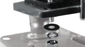
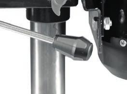
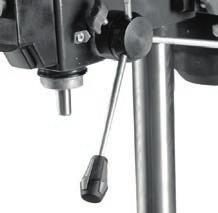
11 G B I E N I CY Do not use the power tool with a damaged cable. Do not touch the damaged cable and pull the mains plug if the cable is damaged while working. Damaged cables increase the risk of electric shock. The device is unsuitable for processing of foods. Edit not work pieces that you can not sure retain. Especially round or uneven workpieces. Avoid abnormal body postures. Ensure secure footing and keep your balance at all times. Assembly The bench drill is supplied disassembled. Clean the column tube (14), baseplate (17), drilling bench (20), vice (23) and the drill chuck (4) beforehand, with a dry cloth. 1. Place the column tube (14) on the baseplate (17). Bolt the column tube (14) to the baseplate (17) with the three assembly srews (16) supplied. Tighten the assembly srews (16) moderately tight so that the threads in the baseplate (17) do not strip. C D E 4. Place the motor unit (13) on the column tube (14). Secure the motor unit (13) with the two clamping screws (27) on the side using the enclosed Allen key (25). 5. Bolt the three drill lifting arms into the spindle guide (9). Tighten the three hole lifting arms with a spanner (AF 6 mm). 6. Release the clamping screw from the depth stop (8). 7. Put the safety device (6) on the upper part of the drill spindle (7). 8. Secure the safety device (6) with the clamping screw (28). 9. Fold the safety device (6) upwards. Insert the chuck (4) on the taper of the drill spindle (7). Push the drill chuck onto the drill chuck tip with a few light taps. Use a plastic hammer for this purpose. Operation 2. Place the drilling bench (20) on the column tube (14). Push the drilling bench (20) into a lower position. Use the 5 bench (20) in a lower position. B 3. Place the vice (23) on the drilling 20 the drilling bench (20) by means of the enclosed assembly screws (22) together with the washer and the lock washer in the order as shown. Caution! Risk of injury! space in which to work and that you do not endanger other people. - All hoods and protective devices must be assembled properly before commissioning. - Disconnect the mains plug before changing the setting on the device. 1 1
12 G B I E N I CY Setting up Place the bench drill on a solid surface. Ideally, bolt the drill to the surface. Use the four holes in the baseplate (17) for this. F Selecting the speed 1. Release the locking bolt (11) on the gear cover (3). 2. Open the gear cover (3). 3. Release the two retaining bolts (12) on the motor unit (13). 4. Slide the motor unit (13) forward a little to release the load on the V-belts (29). 5. Place the V-belts (29) on the desired Spindle-side drive pulley ( F 30) A B C D I II III Motor side drive pulley ( F 31) Pos. speed [1/min] Pos. speed [1/min] Pos. speed [1/min] 1. D - I D - I I I B - I I I D - I I B - I A - I I C - I C - I I A - I I I The gear cover (3) is equipped with a interlock switch (32). If the gear cover (3) is not closed correctly, the device cannot be switched on. 6. Slide the motor unit (13) back to tension the V-belts (29) again. 7. The V-belts (29) are correctly tensioned when they give way slightly when pressed. 8. Tighten the retaining bolts (12) on the motor unit (13) again. 9. Close the gear cover (3). Fasten the locking bolt (11) on the gear cover. Recommended speeds for different drill sizes and materials: [mm] [mm] [1/min] < 3 < > 8 >
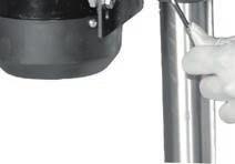
13 G B I E N I CY Checking the V-belts 1. Release the locking bolt (11) on the gear cover (3). 2. Open the gear cover (3). 3. Check the tension of the V-belts (29). 4. The V-belts (29) are correctly tensioned when they give way slightly when pressed. 5. Check the V-belts (29) for tears, cuts or other damage. 6. Close the gear cover (3). Fasten the locking bolt (11) on the gear cover (3). Tensioning the V-belts 1. Release the locking bolt (11) on the gear cover (3). 2. Open the gear cover (3). 3. Release the retaining bolts (12) on the motor unit (13). 4. Slide the motor unit (13) back to tension the V-belts (29). 5. The V-belts (29) are correctly tensioned when they give way slightly when pressed. 6. Tighten the retaining bolts (12) on the motor unit (13) again. 7. Close the gear cover (3). Fasten the locking bolt (12) on the gear cover (3). Adjusting the Drilling Bench 1. Release the locking handle (15). 2. Push the drilling bench (20) to the desired height. 3. Pivot the drilling bench (20) to the desired position. 4. Fasten the drilling bench (20) again with the locking handle (15). 5. You can also adjust the tilt angle of the drilling bench (20). To do this, release the retaining screw (19) (AF 19 mm) under the drilling bench (20). Tilt the drilling bench (20) as desired to the right or left up to a max. of 45 and secure the drilling bench (20) again with the retaining screw (19). Preselecting the Drilling Depth 1. Release the locking screw from the depth stop (8). 2. Lower the drilling spindle (7) with the mounted tool on to the workpiece. 3. Turn the scale until the silver marking arrow attached to the motor unit (13) is pointing to the zero line of the scale. 4. Now turn the scale to the desired drilling depth and tighten the locking screw (8) again. 5. Turn the drilling spindle (7) back to its starting position. Changing the Bit Remove the plug from the mains socket before changing the bit. This will prevent an accidental start-up. 1. Fold the safety device (6) up. 2. Release the retaining jaws of the drill chuck (4) with the drill chuck key (26) 0 3. Remove the bit. 4. Insert a new bit. 5. Tighten the retaining jaws of the drill chuck (4) with the drill chuck key (26). 2 holder again (10). 7. Check that the bit is centred. 8. Fold the safety device (6) down again. 9. Carry out a brief trial run in order to check the drill for true running. Under no circumstances must you leave the drill chuck key (26) inserted. 1 3
14 G B I E N I CY Drilling 1. Turn the appliance on. 2. Turn one of the drill lifting arms anticlockwise 3. The drill chuck (4) is lowered. 4. Drill into the workpiece at the appropriate feed rate and to the desired depth. 5. Be aware of any necessary chip breaking on the way to the desired depth. 6. Move the bit slowly back to the stop position. General Information The feed rate and spindle speed are decisive for the service life of the bit. - The cutting speed is determined by the speed of the drill spindle and by the diameter of the bit. - In principle, therefore, the larger the bit diameter, the lower the speed that should be selected. - For workpieces of greater strength, the cutting pressure must be higher. - Repeated withdrawal of the bit enables easier chip removal. deep holes. Reduce the feed rate and speed in this case. - To avoid excessive wear on the cutting surface of the bit, for drill holes over 8 0 drill with a bit with a smaller diameter. Switching on and off Make sure that the power supply voltage matches the voltage rating indicated on the device s type plate. Connect the machine to the power supply. Caution! Fold the protective device (6) down before you switch on the machine. Switching on: Press the on switch (2). Switching off: Press the off switch (1). Emergency stop: Press the emergency stop button (5). After pressing the emergency stop button, the emergency stop button (5) must be activated again by turning it. Press the on switch (2) to restart the device. Clamping the Workpieces Only work with workpieces that can be securely clamped. The workpiece must not yield too much. Otherwise it is nor possible to apply adequate tension. The workpiece must not be too small or too large either. Removing Blockages - You should always select a suitable feed rate which allows trouble-free chip breaking. - If the bit is jammed in the workpiece, turn off the power and unplug the power cord. Turn the bit on the drill chuck anticlockwise with a little jerk to break the chip and release the bit again. - If a fragment is produced during the processing of the workpiece, turn off the power and unplug the power cord. Use a pair of pliers and remove the uncontrolled way. 1 4
15 G B I E N I CY Cleaning and maintenance Pull the mains plug before any adjustments, maintenance or repair. Have any work on the device that is not described in this instruction guide performed by a professional. Only use original parts. Allow the device to cool off before any maintenance or cleaning is undertaken. There is a risk of burning! Always check the device before using it for obvious defects such as loose, worn or damaged parts, correct the positioning of screws or other parts. Exchange the damaged parts. Cleaning Do not use any cleaning agents or solvents. Chemical substances can etch the plastic parts of the device. Never clean the device under running water. Thoroughly clean the device after every use. Clean the ventilation openings and the surface of the device with a soft brush or cloth. Remove chips, dust and dirt with a vacuum cleaner if necessary. Lubricate moving parts regularly. Do not allow lubricants to come into contact with switches, V-belts, pulleys and drill lifting arms. G Maintenance Repeat the maintenance after every 5 hours of operation. 1. Release the locking bolt ( A 11) on the gear cover (3). 2. Open the gear cover (3). 3. Release the two retaining bolts (12) on the motor unit (13). 4. Slide the motor unit (13) forward a little to release the load on the V-belts ( F 29). 5. Remove both V-belts ( F 29). 6. Remove the middle drive disc (33) and its retainer (34). 7. Clean the bearing point retainer (35+36) and grease this with a commercially available multi-purpose grease. 8. Re-insert the retainer (34) and the drive disc (33). Tighten the V-belts ( F 29) again. 9. Slide the motor unit (13) back to tension the V-belts ( F 29) again. 10.The V-belts ( F 29) are correctly tensioned when they give way slightly when pressed. 11.Tighten the retaining bolts (12) on the motor unit (13) again. 12.Close the gear cover (3). Fasten the locking bolt ( A 11) on the gear cover. Storage Store the appliance in a dry place well out of reach of children. The device can be relocated over a short distance with two people. Relocating the device over a longer distance generally has to take place with a transport aid. 1 5
16 G B I E N I CY Transport Do not carry the bench drill holding it on the motor unit. Caution! Hot surface. There is a risk of burns. Only transport the machine when the motor unit ( A 13) has cooled down completely. If possible, carry the bench drill together with another person. Grip the baseplate ( A 17) with one hand and stabilise the machine on the drive cover ( A 3) with the other hand. Waste disposal and environmental protection Be environmentally friendly. Return the tool, accessories and packaging to a recy- them. Electrical machines do not belong with domestic waste. Hand over the device at an utilization location. The plastic and metal parts employed can be separated out and thus recycled use can be implemented. Ask our Service-Center for details. Defective units returned to us will be disposed of for free. Troubleshooting Problem Possible Cause Error correction Device doesn t start Strong vibrations Loud squeaking noise Emergency stop switch (5) has been triggered No mains voltage Main circuit breaker is tripped Reactivate the emergency stop switch (5) by turning it. Press the on switch (1) to restart the device Check the socket, mains supply cable, cord, mains plug; if necessary, have them repaired by a quali- Check the main fuse Repair by Customer Care Repair by Customer Care Check V-belt tension and tighten the locking screw (12) On/off switch (1/2) is broken Motor faulty 3 place Bit not centrally clamped Check the bit in the drill chuck (4) V-belt tension is too high Check V-belt tension Damaged V-belts (29) Check V-belts (29) Damaged pulley Check pulleys 1 6
17 G B I E N I CY Replacement parts/accessories Spare parts and accessories can be obtained at If you do not have internet access, please contact the Service Centre via telephone (see Service-Center page 19). Please have the order number mentioned below ready. Position Position Description Ordernumber Manual drawing Safety device, complete Drilling bench, complete /2 44,46-51,54 On-/Off switch, complete Emergency stop switch ,68 Drill lift arm Vice F V-belt, set Drill chuck ,121 Hinge of the gear cover Screw for depth limiter Spring for spindle return Screw for V-belt tension Drill chuck key
18 G B I E N I CY Guarantee Dear Customer, This equipment is provided with a 3-year guarantee from the date of purchase. In case of defects, you have statutory rights against the seller of the product. These statutory rights are not restricted by our guarantee presented below. Terms of Guarantee The term of the guarantee begins on the date of purchase. Please retain the original receipt. This document is required as proof of purchase. If a material or manufacturing defect occurs within three years of the date of purchase of this product, we will repair or replace at our choice the product for you free of charge. This guarantee requires the defective equipment and proof of purchase to be presented within the three-year period with a brief written description of what constitutes the defect and when it occurred. If the defect is covered by our guarantee, you will receive either the repaired product or a new product. No new guarantee period begins on repair or replacement of the product. Guarantee Period and Statutory Claims for Defects The guarantee period is not extended by the guarantee service. This also applies for replaced or repaired parts. Any damages and defects already present at the time of purchase must be reported immediately after unpacking. Repairs arising after expiry of the guarantee period are chargeable. Guarantee Cover The equipment has been carefully produced in accordance with strict quality guidelines and conscientiously checked prior to delivery. The guarantee applies for all material and manufacturing defects. This guarantee does not extend to cover product parts that are subject to normal wear and may therefore be considered as wearing parts (e.g. V-belts) or to cover damage to breakable parts (e.g. switches). This guarantee shall be invalid if the product has been damaged, used incorrectly or not maintained. Precise adherence to all of manual is required for proper use of the product. Intended uses and actions against which the operating manual advises or warns must be categorically avoided. The product is designed only for private and not commercial use. The guarantee will be invalidated in case of misuse or improper handling, use of force, or interventions not undertaken by our authorised service branch. Processing in Case of Guarantee Please have the receipt and item number (IAN ) ready as proof of purchase for all enquiries. ing plate. Should functional errors or other defects occur, please initially contact the telephone or by . You will then receive further information on the processing of your complaint. 1 8
19 G B G B I E N I CY After consultation with our customer service, a product recorded as defective can be sent postage paid to the service address communicated to you, with the proof of purchase (receipt) and speci- and when it occurred. In order to avoid acceptance problems and additional costs, please be sure to use only the address communicated to you. Ensure that the consignment is not sent carriage forward or by bulky goods, express or other special freight. Please send the equipment inc. all accessories supplied at the time of purchase and ensure adequate, safe transport packaging. Repair Service For a charge, repairs not covered by the guarantee can be carried out by our service branch, which will be happy to issue a cost estimate for you. We can handle only equipment that has been sent with adequate packaging and postage. Attention: Please send your equipment to our service branch in clean condition and with an indication of the defect. Equipment sent carriage forward or by bulky goods, express or other special freight will not be accepted. We will dispose of your defective devices free of charge when you send them to us. Service-Center I E N I CY Importer Service Great Britain ( 0.10/Min.) IAN Service Ireland Service Northern Ireland (0,08 EUR/Min., (peak)) (0,06 EUR/Min., (off peak)) IAN Service Cyprus IAN Please note that the following address is not a service address. Please initially con- Grizzly Tools GmbH & Co KG Stockstädter Straße Großostheim Germany 1 9
20 G R CY Περιεχόμενα εισαγωγή Αλλαγή εργαλείου Σκοπός χρήσης Διάτρηση Γενική περιγραφή Γενικές υποδείξεις Παραδοτέα υλικά Ενεργοποίηση και Απενεργοποίηση. 31 Περιγραφή Λειτουργίας Σύσφιξη τεμαχίων επεξεργασίας Επισκόπηση Απομάκρυνση εμφράξεων Τεχνικά Χαρακτηριστικά Καθαρισμός και Συντήρηση Υποδείξεις ασφάλειας Καθαρισμός Σύμβολα και εικονοσύμβολα Συντήρηση Γενικές υποδείξεις ασφαλείας Αποθήκευση Γενικές υποδείξεις ασφαλείας για Μεταφορά ηλεκτρικά εργαλεία Απόσυρση/προστασία Υποδείξεις ασφάλειας για δράπανα με του περιβάλλοντος ορθοστάτη Ανταλλακτικά / Αξεσουάρ Συναρμολόγηση Ανίχνευση βλαβών Χρήση Гаранция Τοποθέτηση...27 Σέρβις επισκευής Επιλογή αριθμού στροφών...28 S e r v i c e - Ce n t e r Έλεγχος τραπεζοειδή ιμάντα...29 εισαγωγέας Τάνυση τραπεζοειδούς ιμάντα...29 Μετάφραση των πρωτότυπων Μετατόπιση πάγκου διάτρησης...29 Οδηγιών χρήσης Προεπιλογή βάθους διάτρησης...29 Επί μέρoυς σχεδιαγράμματα εισαγωγή Συγχαρητήρια για την αγορά της νέας συσκευής σας. Προτιμήσατε να αγοράσετε ένα προϊόν ανώτερης ποιότητας. Η ποιότητα αυτής της συσκευής ελέγχθηκε κατά τη διάρκεια της παραγωγής, αλλά και σε τελικό έλεγχο. Με τον τρόπο αυτό εξασφαλίστηκε η λειτουργικότητα της συσκευής σας. Δεν αποκλείεται σε μεμονωμένες περιπτώσεις να βρίσκονται στη συσκευή ή στους σωλήνες κατάλοιπα νερού ή λιπαντικών. Το γεγονός αυτό δεν αποτελεί ελάττωμα ή βλάβη της συσκευής και δεν είναι καθόλου ανησυχητικό. Οι οδηγίες χρήσης αποτελούν αναπόσπαστο τμήμα αυτού του προϊόντος. Περιέχουν σημαντικές υποδείξεις για την ασφάλεια, τη χρήση και διάθεση της συσκευής. Πριν τη χρήση του προϊόντος να εξοικειωθείτε με όλες τις οδηγίες χειρισμούς και τις υποδείξεις ασφαλείας. Να χρησιμοποιείτε το προϊόν μόνο όπως περιγράφεται και μόνο για τον αναφερόμενο σκοπό. Να φυλάξετε καλά τις οδηγίες και να τις παραδώσετε σε τρίτους μαζί με το προϊόν. 2 0
21 G R CY Σκοπός χρήσης Το κολονάτο δράπανο προορίζεται για διάτρηση σε μέταλλο, ξύλο, πλαστικό και πλάκες. Μπορούν να χρησιμοποιηθούν τρυπάνια κυλινδρικού άξονα με διάμετρο διάτρησης από 1,5 mm έως 16 mm. Η συσκευή προορίζεται για οικιακή χρήση. Δεν είναι φτιαγμένη για συνεχή, επαγγελματική χρήση. Η συσκευή δεν προορίζεται για χρήση από άτομα κάτω των 16 ετών. Ανήλικοι κάτω των 16 ετών δεν επιτρέπεται να χρησιμοποιούν τη συσκευή χωρίς επίβλεψη. Ο κατασκευαστής δεν αναλαμβάνει καμία ευθύνη για φθορές που οφείλονται σε μη ορθή ή λάθος χρήση. Γενική περιγραφή Θα βρείτε τις απεικονίσεις στην μπροστινή και πίσω αναδιπλωνόμενη σελίδα. Παραδοτέα υλικά Βγάλτε τη συσκευή από τη συσκευασία και ελέγξτε, αν είναι πλήρης. Διαθέστε τα υλικά συσκευασίας σύμφωνα με τους κανονισμούς. - Πλάκα βάσης - Πάγκος διάτρησης - Σωλήνας στήλης - Μονάδα μοτέρ - 3 Βραχίονες διαδρομής διάτρησης - Διάταξη προστασίας - Τσοκ - Κλειδί τσοκ - Εσωτερικό εξάγωνο κλειδί - Μέγγενη - Υλικά συναρμολόγησης - Οδηγιών χρήσης Περιγραφή Λειτουργίας Τη λειτουργία των εξαρτημάτων χειρισμού θα την βρείτε στις ακόλουθες περιγραφές. Επισκόπηση A 1 Διακόπτης απενεργοποίησης 2 Διακόπτης ενεργοποίησης 3 Επικάλυψη μηχανισμού μετάδοσης κίνησης 4 Τσοκ 5 Διακόπτης έκτακτης απενεργοποίησης 6 Διάταξη προστασίας 7 Άτρακτος διάτρησης 8 Κοχλίας ασφάλισης αναστολέα βάθους 9 Χειροκίνητος οδηγός ατράκτου με 3 βραχίονες διαδρομής διάτρησης 10 Συγκράτηση για κλειδί τσοκ 11 Βίδα ασφάλισης επικάλυψης μηχανισμού μετάδοσης κίνησης 12 Κοχλίας ασφάλισης Μονάδα μοτέρ 13 Μονάδα μοτέρ 14 Σωλήνας στήλης 15 Εγκάρσια ράβδος 16 3 Βίδες συναρμολόγησης 17 Πλάκα βάσης 18 Γωνιακή διαβάθμιση 19 Κοχλίας ασφάλισης πάγκου διάτρησης, Κλίση 20 Πάγκος διάτρησης 21 Αναστολέας βάθους με διαβάθμιση 22 Υλικό συναρμολόγησης μέγγενης 23 Μέγγενη 24 Σιαγόνα σύσφιξης 25 Εσωτερικό εξάγωνο κλειδί 26 Κλειδί τσοκ 27 Βίδα σύσφιξης, μονάδα μοτέρ 2 1
22 G R CY E F Βίδα σύσφιξης, Διάταξη προστασίας 29 Τραπεζοειδής ιμάντας 30 Δίσκος μετάδοσης κίνησης πλευράς ατράκτου 31 Δίσκος μετάδοσης κίνησης πλευράς μοτέρ 32 Διακόπτης ασφάλισης Τεχνικά Χαρακτηριστικά Επιτραπεζιο δραπανο..... P TB M D4 Ονομαστική τάση εισόδου..230 V~, 50 Hz Απόδοση W (S2 15 min)* Αριθμός στροφών ρελαντί (n 0 ) Άτρακτος min -1 Μοτέρ min -1 Κατηγορία προστασίας... I Είδoς προστασίας...ipx0 Βάρος...17 kg Τσοκ... B16 (1,5 χιλ. έως 16 χιλ.) Διαδρομή ατράκτου...50 χιλ. Μέγεθος τεμαχίου επεξεργασίας... μέγ. 60 χιλ. Στάθμη ηχητικής πίεσης (L pa )...71 db(a); K pa = 3 db Επιτρεπόμενη στάθμη θορύβου (L WA ) μετρημέvη db(a); K WA = 3 db εγγυημένη db(a) Δόνηση (a h )... 2,39 m/s 2 K= 1,5 m/s 2 * Μετά από τη συνεχόμενη διάρκεια λειτουργίας των 15 λεπτών ακολουθεί μια παύση ηρεμίας, έως ότου η θερμοκρασία συσκευής αποκλίνει λιγότερο από 2 K (2 C) από τη θερμοκρασία δωματίου. Τα επίπεδα θορύβου και κραδασμών είναι σύμφωνα με τα πρότυπα και τους κανονισμούς της δήλωσης συμμόρφωσης. Η αναγραφόμενη τιμή δονήσεων μετρήθηκε σύμφωνα με μια τυποποιημένη διαδικασία ελέγχου και μπορεί να χρησιμοποιηθεί για τη σύγκριση με άλλα ηλεκτρικά εργαλεία. Η αναγραφόμενη τιμή δονήσεων μπορεί να χρησιμοποιηθεί και για έναν αρχικό υπολογισμό της έκθεσης Προειδοποίηση: : Η τιμή δονήσεων μπορεί να διαφέρει κατά την πραγματική χρήση του ηλεκτρικού εργαλείου, ανάλογα από τον τρόπο χρήσης του ηλεκτρικού εργαλείου. Προσπαθείτε να διατηρείτε την επιβάρυνση λόγω κραδασμών όσο μικρότερη γίνεται. Μέτρα για τη μείωση της επιβάρυνσης λόγω κραδασμών είναι για παράδειγμα η χρήση γαντιών κατά τη χρήση του εργαλείου και ο περιορισμός του χρόνου εργασίας. Εδώ πρέπει να ληφθούν υπόψιν όλα τα στάδια λειτουργίας (για παράδειγμα ο χρόνος κατά τον οποίο το ηλεκτρικό εργαλείο είναι απενεργοποιημένο και ο χρόνος κατά τον οποίο το ηλεκτρικό εργαλείο είναι μεν ενεργοποιημένο, αλλά λειτουργεί χωρίς επιβάρυνση). Υποδείξεις ασφάλειας Προσοχή! Προσοχή! Κατά τη χρήση ηλεκτρικών εργαλείων λάβετε τα ακόλουθα βασικά μέτρα ασφαλείας για να αποφύγετε τον κίνδυνο ηλεκτροπληξίας, τραυματισμού και πυρκαγιάς. Διαβάστε όλες αυτές τις υποδείξεις προτού χρησιμοποιήσετε το παρόν ηλεκτρικό εργαλείο και φυλάξτε τις υποδείξεις ασφάλειας καλά.
23 G R CY Σύμβολα και εικονοσύμβολα Σήματα εικόνες στη συσκευή: Προσοχή! Κίνδυνος ηλεκτροπληξίας! Βγάζετε το φις από την πρίζα, - όταν δε χρησιμοποιείτε τη συσκευή, όταν τη μεταφέρετε ή την αφήνετε ανεπίβλεπτη. Διαβάστε προσεκτικά ολόκληρη την οδηγία χειρισμού! Φοράτε προστατευτικά ματιών και ακοής Μαζεύετε τα μακριά μαλλιά. Χρησιμοποιείτε ένα δίχτυ μαλλιών. Μην φοράτε γάντια. Κίνδυνος τραυματισμού από περιστρεφόμενα εργαλεία! Φυλάτε μακριά τα χέρια σας! Προσοχή! Καυτή επιφάνεια. Υπάρχει κίνδυνος εγκαύματος. Μην πετάτε τις ηλεκτρικές συσκευές στα σκουπίδια. Σύμβολα στις οδηγίες: Σύμβολα κινδύνου με στοιχεία για την πρόληψη προσωπικών και υλικών ζημιών. Σύμβολο υποχρέωσης με στοιχεία για την πρόληψη ζημιών. Συνδέστε τη συσκευή στην τάση δικτύου. Αποσυνδέστε το βύσμα δικτύου. Σύμβολο υπόδειξης με πληροφορίες για τον καλύτερο χειρισμό της συσκευής. χάλυβα ξύλο Γενικές υποδείξεις ασφαλείας Προσοχή! Κατά τη χρήση ηλεκτρικών εργαλείων λάβετε τα ακόλουθα βασικά μέτρα ασφαλείας για να αποφύγετε τον κίνδυνο ηλεκτροπληξίας, τραυματισμού και πυρκαγιάς: Υφίσταται κίνδυνος τραυματισμού. Γενικές υποδείξεις ασφαλείας για ηλεκτρικά εργαλεία ΠΡΟΕΙΔΟΠΟΙΗΣΗ! Διαβάστε όλες τις υποδείξεις ασφαλείας και τις οδηγίες. Παραλείψεις στην τήρηση των υποδείξεων ασφαλείας και των οδηγιών μπορούν να οδηγήσουν σε ηλεκτροπληξία, πυρκαγιά και/ή βαρείς τραυματισμούς. Διατηρείτε όλες τις υποδείξεις ασφαλείας και τις οδηγίες για μελλοντική αναφορά. Η έννοια ηλεκτρικά εργαλεία, που χρησιμοποιείται στις υποδείξεις ασφαλείας, αναφέρεται σε ηλεκτρικά εργαλεία που λειτουργούνται με το ηλεκτρικό δίκτυο (με καλώδιο ρεύματος) και σε ηλεκτρικά εργαλεία που λειτουργούνται με συσσωρευτή (δίχως καλώδιο ρεύματος). 2 3
24 G R CY Ασφαλής εργασία: Να κρατάτε τη θέση εργασίας πάντα τακτική. Εάν δεν τηρείτε τάξη στη θέση εργασίας, δεν μπορούν να αποκλεισθούν ατυχήματα. Να λάβετε υπόψη τις επιδράσεις του περιβάλλοντος. - Μην εκθέτετε ηλεκτρικές συσκευές σε βροχή. - Ποτέ μη χρησιμοποιείτε τα ηλεκτρικά εργαλεία σε υγρό περιβάλλον. - Να φροντίζετε για καλό φωτισμό της θέσης εργασίας. - Μη χρησιμοποιείτε ηλεκτρικά εργαλεία σε σημεία όπου υφίσταται κίνδυνος πυρκαγιάς ή έκρηξης. Προστατέψτε τον εαυτό σας από ηλεκτροπληξία. Να αποφεύγετε την επαφή του σώματος με μη γειωμένα τμήματα (π.χ. σωλήνες, ηλεκτρικά σώματα, ηλεκτρικές εστίες, ψυκτικές συσκευές). Να κρατάτε μακριά τα άλλα άτομα. Μην αφήνετε άλλα άτομα, ειδικά μην αφήνετε παιδιά, να αγγίζουν την ηλεκτρική συσκευή ή το καλώδιο. Να τα κρατάτε μακριά από την περιοχή εργασίας. Να φυλάγετε τις ηλεκτρικές συσκευές σε ασφαλή σημεία. Οι ηλεκτρικές συσκευές που δεν χρησιμοποιούνται να φυλάγονται σε στεγνό χώρο, σε ψηλό σημείο ή σε κλειδωμένο χώρο, μακριά από παιδιά. Μην υπερφορτώνετε το ηλεκτρικό σας εργαλείο. Εργάζεστε καλύτερα και ασφαλέστερα στο αναφερόμενο πεδίο ισχύος. Να χρησιμοποιείτε τα σωστά ηλεκτρικά εργαλεία. - Μη χρησιμοποιείτε αδύναμες μηχανές για βαριές εργασίες. - Μη χρησιμοποιείτε τα ηλεκτρικά εργαλεία για εργασίες για τις οποίες δεν προορίζονται. Μη χρησιμοποιείτε για παράδειγμα κυκλικό πριόνι χεριού για να κόβετε κλαδιά ή χοντρά ξύλα. Να φοράτε πάντα τον κατάλληλο ρουχισμό εργασίας. - Μη φοράτε φαρδιά ρούχα ή κοσμήματα γιατί θα μπορούσαν να πιαστούν από τα κινούμενα τμήματα. - Σε εργασίες στο ύπαιθρο συνιστώνται λαστιχένια γάντια και αντιολισθητικά παπούτσια. - Εάν έχετε μακριά μαλλιά να φοράτε ένα δίχτυ. Να χρησιμοποιείτε μέσα ατομικής προστασίας - Να φοράτε οπωσδήποτε προστατευτικά γυαλιά. Σε περίπτωση μη τήρησης των υποδείξεων δεν αποκλείονται τραυματισμοί των ματιών από σπινθήρες ή σωματίδια λείανσης. - Σε περίπτωση εργασιών με σκόνη, να χρησιμοποιείτε μάσκα για προστασία της αναπνοής. Συνδέστε το σύστημα αναρρόφησης σκόνης. Εάν υπάρχουν συνδέσεις για αναρρόφηση της σκόνης και σύστημα συλλογής, σιγουρευτείτε πως έχουν συνδεθεί και χρησιμοποιούνται σωστά. Μη χρησιμοποιείτε το καλώδιο για εργασίες για τις οποίες δεν προορίζεται. Μη χρησιμοποιείτε το καλώδιο για να τραβήξετε το βύσμα από την πρίζα. Να προστατεύετε το καλώδιο από ψηλές θερμοκρασίες, λάδι και αιχμηρά αντικείμενα. Να ασφαλίζετε το εργαλείο Να χρησιμοποιείτε συστήματα συγκράτησης ή μία μέγγενη για τη συγκράτηση του κατεργαστέου αντικειμένου. Με τον τρόπο αυτό συγκρατείται ασφαλέστερα από ό,τι με το χέρι. Να αποφεύγετε τη μη φυσιολογική στάση του σώματος. Φροντίστε να 2 4
25 G R CY στέκεστε σταθερά και να κρατάτε πάντα την ισορροπία σας. Να περιποιήστε τα εργαλεία σας - Να διατηρείτε τα εργαλεία σας τροχισμένα και καθαρά για να μπορείτε να εργάζεστε καλύτερα και ασφαλέστερα. - Να ακολουθείτε τις υποδείξεις λίπανσης και αλλαγής εργαλείων. - Να ελέγχετε τακτικά το καλώδιο της ηλεκτρικής συσκευής και σε περίπτωση ελαττωμάτων να αντικαθίσταται από αναγνωρισμένο και ειδικευμένο τεχνίτη.. - Να ελέγχετε τακτικά τις επεκτάσεις καλωδίων που πρέπει να αντικαθίστανται εάν είναι ελαττωματικές. - Να διατηρείτε τις χειρολαβές στεγνές και ελεύθερες από λάδια και λίπη. Να βγάζετε το βύσμα από την πρίζα Όταν δεν χρησιμοποιείτε το ηλεκτρικό εργαλείο, πριν από εργασίες συντήρησης και κατά την αλλαγή εργαλείων όπως π.χ. δίσκο, τρυπάνι και φρέζα. Μην αφήνετε επάνω στη συσκευή κλειδιά εργαλείων. Πριν την ενεργοποίηση να ελέγχετε, εάν έχουν απομακρυνθεί τα κλειδιά και εργαλεία ρύθμισης. Να αποφεύγετε αθέλητη ενεργοποίηση. Να σιγουρεύεστε πως ο διακόπτης έχει απενεργοποιηθεί όταν βάζετε το βύσμα στην πρίζα. Για το ύπαιθρο να χρησιμοποιείτε επέκταση καλωδίου. Στο ύπαιθρο να χρησιμοποιείτε μόνο τα για το σκοπό αυτό εγκεκριμένα καλώδια επέκτασης (μπαλαντέζες) με την ανάλογη σήμανση. Να είστε πάντα προσεκτικοί. Να προσέχετε τί κάνετε. Να εργάζεστε συνετά. Μη χρησιμοποιείτε το ηλεκτρικό εργαλείο όταν είστε αφηρημένοι. Να ελέγχετε το εργαλείο για ενδεχόμενες βλάβες. - Πριν από περαιτέρω χρήση του εργαλείου να ελέγχονται προσεκτικά τα συστήματα ασφαλείας ή ελαφρά ελαττωματικά τμήματα για την άψογη λειτουργία τους σύμφωνα με το σκοπό για τον οποίο προορίζονται. Σέρβις: Η επισκευή του ηλεκτρικού σας εργαλείου να εκτελείται μόνο από εξειδικευμένο προσωπικό και να χρησιμοποιούνται μόνο γνήσια ανταλλακτικά. Έτσι εξασφαλίζεται η ασφάλεια του ηλεκτρικού σας εργαλείου. Υποδείξεις ασφάλειας για δράπανα με ορθοστάτη Οι προειδοποιητικές πινακίδες δεν πρέπει ποτέ να είναι σε δυσανάγνωστη κατάσταση. Στερεώνετε το ηλεκτρικό εργαλείο σε μια σταθερή, ίσια και οριζόντια επιφάνεια. Εάν το ηλεκτρικό εργαλείο μπορεί να γλιστρήσει ή κουνιέται, δεν μπορεί το εργαλείο χρήσης να οδηγείται ομοιόμορφα και με ασφάλεια. Διατηρείτε την επιφάνεια εργασίας, εκτός του τεμαχίου επεξεργασίας, καθαρή. Αιχμηρά ρινίσματα διάτρησης και αντικείμενα μπορεί να οδηγήσουν σε τραυματισμούς. Οι αναμείξεις υλικών είναι ιδιαίτερα επικίνδυνες. Η σκόνη ελαφριών μετάλλων μπορεί να αναφλεγεί ή εκραγεί. Πριν από την έναρξη εργασίας ρυθμίζετε τον σωστό αριθμό στροφών. Ο αριθμός στροφών πρέπει να αντιστοιχεί στην διάμετρο διάτρησης και στο υλικό που θα διατρηθεί. Σε λάθος 2 5
26 G R CY ρυθμισμένο αριθμό στροφών, μπορεί το εργαλείο χρήσης να μαγκώσει στο τεμάχιο επεξεργασίας. Οδηγείτε το εργαλείο χρήσης μόνο ενεργοποιημένο προς το τεμάχιο επεξεργασίας. Αλλιώς υπάρχει κίνδυνος να μαγκώσει το εργαλείο χρήσης στο τεμάχιο επεξεργασίας και το τεμάχιο επεξεργασίας να συμπαρασυρθεί. Αυτό μπορεί να οδηγήσει σε τραυματισμούς. Μην αγγίζετε με τα χέρια σας στον τομέα διάτρησης όσο λειτουργεί το ηλεκτρικό εργαλείο. Κατά την επαφή με το εργαλείο χρήσης, υπάρχει κίνδυνος τραυματισμού. Ποτέ μην απομακρύνετε ρινίσματα από τον τομέα διάτρησης, όσο λειτουργεί το ηλεκτρικό εργαλείο. Οδηγείτε πάντα πρώτα την μονάδα μετάδοσης κίνησης στην θέση ηρεμίας και απενεργοποιείτε το ηλεκτρικό εργαλείο. Μην απομακρύνετε εμφανιζόμενα ρινίσματα με γυμνά χέρια. Ιδιαίτερα μέσω καυτών και αιχμηρών μεταλλικών ρινισμάτων, υπάρχει κίνδυνος τραυματισμού. Μπορείτε να σπάτε μεγάλα ρινίσματα διάτρησης διακόπτοντας την διαδικασία διάτρησης μέσω σύντομης περιστροφής προς τα πίσω του περιστρεφόμενου τροχού. Μέσω μακριών ρινισμάτων διάτρησης υπάρχει κίνδυνος τραυματισμού. Διατηρείτε τις λαβές στεγνές, καθαρές και χωρίς λάδια και γράσα. Λαβές με γράσα, λάδια είναι ολισθηρές και οδηγούν σε απώλεια του ελέγχου. Χρησιμοποιείτε διατάξεις σύσφιξης για να σφίγγετε το τεμάχιο επεξεργασίας. Μην επεξεργάζεστε τεμάχια επεξεργασίας, τα οποία είναι πολύ μικρά για να σφιχτούν. Όταν κρατάτε το τεμάχιο επεξεργασίας με το χέρι, δεν μπορείτε να το ασφαλίσετε επαρκώς έναντι συστροφής και συνεπώς μπορεί να τραυματιστείτε. Απενεργοποιήστε αμέσως το ηλεκτρικό εργαλείο, εάν έχει μπλοκάρει το εργαλείο χρήσης. Το εργαλείο χρήσης μπλοκάρει όταν: - υπερφορτώνεται το ηλεκτρικό εργαλείο ή - γέρνει προς το τεμάχιο επεξεργασίας. Μην πιάνετε το εργαλείο χρήσης μετά την εργασία προτού κρυώσει. Το εργαλείο χρήσης θερμαίνεται πολύ κατά την εργασία. Ελέγχετε τακτικά το καλώδιο και επιτρέπετε επισκευή ενός φθαρμένου καλωδίου μόνο από μια εξουσιοδοτημένη υπηρεσία εξυπηρέτησης πελατών. Αντικαθιστάτε τα φθαρμένα καλώδια επέκτασης. Έτσι εξασφαλίζεται ότι παραμένει η ασφάλεια του ηλεκτρικού εργαλείου. Φυλάτε το μη χρησιμοποιούμενο ηλεκτρικό εργαλείο σε ασφαλές σημείο. Η θέση αποθήκευσης πρέπει να είναι στεγνή και να ασφαλίζει. Έτσι εμποδίζεται φθορά του ηλεκτρικού εργαλείου από την αποθήκευση ή χειρισμός του από άπειρα άτομα. Μην αποθέτετε ποτέ το εργαλείο πριν σταματήσει τελείως. Εργαλεία χρήσης που συνεχίζουν να λειτουργούν μπορεί να προκαλέσουν τραυματισμούς. Μην χρησιμοποιείτε το ηλεκτρικό εργαλείο με φθαρμένο καλώδιο. Μην αγγίζετε το φθαρμένο καλώδιο και τραβήξτε το βύσμα εάν το καλώδιο φθαρεί κατά τη διάρκεια της εργασίας. Τα φθαρμένα καλώδια αυξάνουν τον κίνδυνο ηλεκτροπληξίας. Αποφεύγετε μια μη φυσιολογική στάση του σώματος. Φροντίζετε για μια ασφαλή στάση και διατηρείτε πάντα την ισορροπία. 2 6
27 G R CY Συναρμολόγηση Το κολονάτο δράπανο αποστέλλεται αποσυναρμολογημένο. Καθαρίστε πρώτα με ένα στεγνό πανί τον σωλήνα στήλης (14), την πλάκα βάσης (17), τον πάγκο διάτρησης (20), την μέγγενη (23) και το τσοκ (4). 1. Τοποθετήστε τον σωλήνα στήλης (14) επάνω στην πλάκα βάσης (17). Βιδώστε τον σωλήνα στήλης (14) με τις τρεις εσώκλειστες εξάγωνες βίδες (16) στην πλάκα βάσης (17). Σφίξτε μέτρια τις βίδες (16), ώστε να μην προκληθεί ζημιά στα σπειρώματα της πλάκας βάσης (17). 2. Τοποθετήστε τον πάγκο διάτρησης (20) στο σωλήνα στήλης (14). Ωθήστε τον πάγκο διάτρησης (20) σε μια κατώτερη θέση. Στερεώστε τον πάγκο διάτρησης (20) με τη βίδα με διάτρητη σφαιρική κεφαλή (15) σε μια κατώτερη θέση. E διάτρησης με ένα διπλό κλειδί (πλάτος κλειδιού 6). 6. Λασκάρετε τον κοχλία ασφάλισης από τον αναστολέα βάθους (8). 7. Τοποθετήστε την διάταξη προστασίας (6) στο άνω τμήμα της ατράκτου διάτρησης (7). 8. Στερεώστε τη διάταξη προστασίας (6) με τη βίδα σύσφιξης (28). 9. Ανοίξτε την διάταξη προστασίας (6) προς τα επάνω. Τοποθετήστε το τσοκ (4) επάνω στον κώνο της ατράκτου διάτρησης (7). Ασφαλίστε το τσοκ (4) με λίγα ελαφριά χτυπήματα στην ακμή τσοκ. Για αυτό χρησιμοποιήστε ένα πλαστικό σφυρί. Χρήση B C D 3. Τοποθετήστε την μέγγενη (23) στον πάγκο διάτρησης (20). Βιδώστε την με τις εσώκλειστες βίδες συναρμολόγησης (22), μαζί με τη ροδέλα και τον ελατηριωτό δακτύλιο σύμφωνα με την απεικονιζόμενη σειρά, σφιχτά με τον πάγκο διάτρησης (20). 4. Τοποθετήστε τη μονάδα μοτέρ (13) στον σωλήνα στήλης (14). Ασφαλίστε τη μονάδα μοτέρ (13) με τις δύο βίδες σύσφιξης (27) στα πλάγια με το εσώκλειστο εσωτερικό εξάγωνο κλειδί (25). 5. Βιδώστε τους τρεις βραχίονες διαδρομής διάτρησης στον οδηγό ατράκτου (9). Σφίξτε τους τρεις βραχίονες διαδρομής Προσοχή! Κίνδυνος τραυματισμού! - Προσέξτε ώστε κατά την εργασία να υπάρχει επαρκής χώρος και να μην τίθενται σε κίνδυνο άλλα άτομα. - Πριν από τη θέση σε λειτουργία πρέπει να έχουν συναρμολογηθεί σωστά όλες οι επικαλύψεις και οι διατάξεις προστασίας. - Τραβήξτε το βύσμα δικτύου, προτού διεξάγετε ρυθμίσεις στη συσκευή Τοποθέτηση Τοποθετήστε το κολονάτο δράπανο σε ένα σταθερό υπόβαθρο. Ιδανικά βιδώστε τη μηχανή στο υπόβαθρο. Για αυτό χρησιμοποιήστε τις τέσσερις οπές διάτρησης στην πλάκα βάσης (17). 2 7
28 G R CY F Επιλογή αριθμού στροφών 1. Λασκάρετε τη βίδα ασφάλισης (11) της επικάλυψης μηχανισμού μετάδοσης κίνησης (3). 2. Ανοίξτε την επικάλυψη μηχανισμού μετάδοσης κίνησης (3). 3. Λασκάρετε και τους δύο κοχλίες ασφάλισης (12) της μονάδας μοτέρ (13). Δίσκος μετάδοσης κίνησης πλευράς ατράκτου ( F 30) A B C D 4. Ωθήστε τη μονάδα μοτέρ (13) λίγο προς τα εμπρός ώστε να αποφορτίσετε τους τραπεζοειδείς ιμάντες (29). 5. Τοποθετήστε τους τραπεζοειδείς ιμάντες (29) στον επιθυμητό συνδυασμό ώστε να επιτύχετε τον δοθέντα αριθμό στροφών: Δίσκος μετάδοσης κίνησης πλευράς μοτέρ ( F 31) I II III Θέση Αριθμός στροφών [1/min] Θέση Αριθμός στροφών [1/min] Θέση Αριθμός στροφών [1/min] 1. D - I D - I I I B - I I I D - I I B - I A - I I C - I C - I I A - I I I Η επικάλυψη μηχανισμού μετάδοσης κίνησης (3) είναι εξοπλισμένη με έναν διακόπτη ασφάλειας (32). Σε λάθος κλεισμένη επικάλυψη μηχανισμού μετάδοσης κίνησης (3) δεν μπορεί να ενεργοποιηθεί η συσκευή. 6. Ωθήστε τη μονάδα μοτέρ (13) προς τα πίσω, ώστε να σφίξετε πάλι τους τραπεζοειδείς ιμάντες (29). 7. Οι τραπεζοειδείς ιμάντες (29) είναι σωστά σφιγμένοι, όταν μπορούν να ωθηθούν ελαφρώς. 8. Στερεώστε πάλι τον κοχλία ασφάλισης (12) της μονάδας μοτέρ (13). 9. Κλείστε την επικάλυψη μηχανισμού μετάδοσης κίνησης (3). Στερεώστε την βίδα ασφάλισης της επικάλυψης μηχανισμού μετάδοσης κίνησης (11). 2 8
29 G R CY Προτεινόμενοι αριθμοί στροφών για διάφορα μεγέθη τρυπανιών και υλικών: [mm] [mm] [1/min] < 3 < > 8 > Έλεγχος τραπεζοειδή ιμάντα 1. Λασκάρετε τη βίδα ασφάλισης (11) της επικάλυψης μηχανισμού μετάδοσης κίνησης (3). 2. Ανοίξτε την επικάλυψη μηχανισμού μετάδοσης κίνησης (3). 3. Ελέγξτε την τάνυση των τραπεζοειδών ιμάντων (29). 4. Οι τραπεζοειδείς ιμάντες (29) είναι σωστά σφιγμένοι, όταν μπορούν να ωθηθούν ελαφρώς. 5. Ελέγξτε τους τραπεζοειδείς ιμάντες (29) για ρωγμές, κοπές ή άλλες ζημιές. 6. Κλείστε την επικάλυψη μηχανισμού μετάδοσης κίνησης (3). Στερεώστε την βίδα ασφάλισης της επικάλυψης μηχανισμού μετάδοσης κίνησης (11). Τάνυση τραπεζοειδούς ιμάντα 1. Λασκάρετε τη βίδα ασφάλισης της επικάλυψης μηχανισμού μετάδοσης κίνησης (11). 2. Ανοίξτε την επικάλυψη μηχανισμού μετάδοσης κίνησης (3). 3. Λασκάρετε και τους δύο κοχλίες ασφάλισης (12) της μονάδας μοτέρ (13). 4. Ωθήστε τη μονάδα μοτέρ (13) προς τα πίσω, ώστε να σφίξετε τους τραπεζοειδείς ιμάντες (29). 5. Οι τραπεζοειδείς ιμάντες (29) είναι σωστά σφιγμένοι, όταν μπορούν να ωθηθούν ελαφρώς. 6. Στερεώστε πάλι τους κοχλίες ασφάλισης (12) της μονάδας μοτέρ (13). 7. Κλείστε την επικάλυψη μηχανισμού μετάδοσης κίνησης (3). Στερεώστε την βίδα ασφάλισης της επικάλυψης μηχανισμού μετάδοσης κίνησης (11). Μετατόπιση πάγκου διάτρησης 1. Λασκάρετε τη βίδα σύσφιξης (15). 2. Ωθήστε τον πάγκο διάτρησης (20) στο επιθυμητό ύψος. 3. Περιστρέψτε τον πάγκο διάτρησης (20) στην επιθυμητή θέση. 4. Στερεώστε πάλι τον πάγκο διάτρησης (20) με την βίδα σύσφιξης (15). 5. Μπορείτε να μετατοπίσετε τον πάγκο διάτρησης (20) και σε κλίση. Λασκάρετε για αυτό την βίδα σύσφιξης (19) (πλάτος κλειδιού 19) κάτω από τον πάγκο διάτρησης. Γείρετε τον πάγκο διάτρησης (20) κατόπιν επιθυμίας έως το μέγ. 45 προς τα δεξιά ή αριστερά και στερεώστε πάλι τον πάγκο διάτρησης (20) με την βίδα σύσφιξης (19). Προεπιλογή βάθους διάτρησης 1. Λασκάρετε τον κοχλία ασφάλισης από τον αναστολέα βάθους (8). 2. Κατεβάστε την άτρακτο διάτρησης (7) με το τοποθετημένο εργαλείο στο τεμάχιο επεξεργασίας. 3. Περιστρέψτε την κλίμακα έως ότου το σημειωμένο στη μονάδα μοτέρ (13) ασημένιο βέλος σήμανσης δείχνει στη γραμμή μηδενός της κλίμακας. 2 9
30 G R CY 4. Περιστρέψτε τώρα την κλίμακα στο επιθυμητό βάθος διάτρησης και βιδώστε πάλι σφιχτά τον κοχλία ασφάλισης (8). 5. Οδηγήστε πάλι την άτρακτο διάτρησης (7) στην αρχική της θέση. Αλλαγή εργαλείου Πριν από την αλλαγή εργαλείου τραβήξτε το βύσμα από την πρίζα. Έτσι εμποδίζετε μη ηθελημένη εκκίνηση. 1. Σηκώστε ψηλά την διάταξη προστασίας (6). 2. Λασκάρετε τις σιαγόνες συγκράτησης του τσοκ (4) με το κλειδί τσοκ (26) έξω από τη βάση (10). 3. Απομακρύνετε το εργαλείο. 4. Τοποθετήστε ένα νέο εργαλείο. 5. Σφίξτε τις σιαγόνες συγκράτησης του τσοκ (4) με το κλειδί τσοκ (26). 6. Στερεώστε πάλι το κλειδί σφιγκτήρα τρυπανιού (26) στη συγκράτηση (10). 7. Ελέγξτε την κεντραρισμένη θέση του εργαλείου. 8. Κατεβάστε πάλι κάτω την διάταξη προστασίας (6). 9. Διεξάγετε μια σύντομη δοκιμαστική χρήση για να ελέγξετε το τρυπάνι για την περιστροφική διαδρομή. Διάτρηση Σε καμία περίπτωση μην αφήσετε μέσα το κλειδί τσοκ. 1. Ενεργοποιήστε τη συσκευή. 2. Περιστρέψτε σε έναν από τους βραχίονες διαδρομής διάτρησης (9) αριστερόστροφα. 3. Το τσοκ (4) βυθίζεται. 4. Τρυπήστε με κατάλληλη ταχύτητα και στο επιθυμητό βάθος στο τεμάχιο επεξεργασίας. 5. Προσέξτε μια ενδεχόμενα απαραίτητη κοπή ρινίσματος κατά τη διαδρομή στο επιθυμητό βάθος διάτρησης. 6. Οδηγήστε το εργαλείο αργά πίσω στην θέση αναστολέα. Γενικές υποδείξεις Η ταχύτητα και ο αριθμός στροφών ατράκτου είναι σημαντικά για τη διάρκεια ζωής του εργαλείου. - Η ταχύτητα κοπής καθορίζεται από τον αριθμό στροφών της ατράκτου διάτρησης και από τη διάμετρο του εργαλείου. - Γι αυτό ισχύει κατά βάση, όσο μεγαλύτερη είναι η διάμετρος εργαλείου, τόσο χαμηλότερος πρέπει να επιλέγεται ο αριθμός στροφών. - Σε υψηλότερη στερεότητα του τεμαχίου επεξεργασίας, πρέπει η πίεση κοπής να είναι υψηλότερη. - Μέσω επανειλημμένης έλξης προς τα πίσω του τεμαχίου επεξεργασίας, φροντίζετε για πιο εύκολη απομάκρυνση των ρινισμάτων. - Η απομάκρυνση ρινισμάτων δυσχεραίνεται ιδιαίτερα σε βαθιές διατρήσεις. Μειώστε εδώ την ταχύτητα και τον αριθμό στροφών. - Προς αποφυγή υπερβολικής φθοράς της κόψης εργαλείου, πρέπει σε διατρήσεις με διάμετρο πάνω από 8,0 mm να κάνετε πρώτα μια αρχική διάτρηση με ένα εργαλείο με μικρή διάμετρο. 3 0
31 G R CY Ενεργοποίηση και Απενεργοποίηση Ελέγξτε η ένταση στο σημείο σύνδεσης με το δίκτυο να είναι ίδια με αυτή που αναφέρεται στον πίνακα της συσκευής. Συνδέστε τη συσκευή στο δίκτυο. Προσοχή! Γυρίστε κάτω τη διάταξη προστασίας (6) προτού ενεργοποιήσετε το μηχάνημα. Ενεργοποίηση: Πατήστε τον διακόπτη ενεργοποίησης (2). Απενεργοποίηση: Πατήστε το διακόπτη απενεργοποίησης (1). Απενεργοποίηση έκτακτης ανάγκης: Πατήστε τον διακόπτη έκτακτης απενεργοποίησης (5) Μετά την πίεση της απενεργοποίησης έκτακτης ανάγκης πρέπει να ενεργοποιηθεί πάλι μέσω περιστροφής ο διακόπτης έκτακτης απενεργοποίησης (5). Πατήστε τον διακόπτη ενεργοποίησης (2) για να εκκινήσετε τη συσκευή. Σύσφιξη τεμαχίων επεξεργασίας Να επεξεργάζεστε μόνο τεμάχια επεξεργασίας, τα οποία στερεώνονται με ασφάλεια. Το τεμάχιο επεξεργασίας δεν πρέπει να υποχωρεί. Αλλιώς δεν μπορεί να εφαρμοστεί ασφαλής τάνυση. Επίσης το τεμάχιο επεξεργασίας δεν μπορεί να είναι πολύ μικρό ή μεγάλο. Απομάκρυνση εμφράξεων - Επιλέγετε κατά βάση μια αντίστοιχη ταχύτητα, ώστε να διευκολύνετε μια το δυνατόν χωρίς βλάβες κοπή ρινισμάτων. - Εάν το εργαλείο έχει μαγκώσει στο τεμάχιο επεξεργασίας, απενεργοποιήστε τη συσκευή και τραβήξτε το βύσμα. Περιστρέψτε το εργαλείο στο τσοκ αριστερόστροφα με ένα μικρό τράνταγμα, ώστε να σπάσετε το ρίνισμα και να απελευθερώσετε πάλι το τεμάχιο επεξεργασίας. - Εάν προκύψει σπασμένο τεμάχιο κατά την επεξεργασία του τεμαχίου επεξεργασίας, απενεργοποιήστε τη συσκευή και τραβήξτε το βύσμα. Χρησιμοποιήστε για βοήθεια μια πένσα και απομακρύνετε το σπασμένο τεμάχιο, ώστε να εμποδίσετε ανεξέλεγκτη εκτόξευση. Καθαρισμός και Συντήρηση Πριν από κάθε ρύθμιση, επισκευή ή συντήρηση αποσυνδέστε από το ρεύμα. Για εργασίες που δεν περιγράφονται στις οδηγίες χρήσεως απευθυνθείτε σε κάποιον ειδικό. Χρησιμοποιείτε μόνο αυθεντικά μέρη. Πριν από κάθε συντήρηση και καθαρισμό, αφήστε τη συσκευή να κρυώσει. Υπάρχει κίνδυνος εγκαύματος! Πριν από κάθε χρήση ελέγξτε τη συσκευή για προφανείς ελλείψεις ή φθορές όπως χαλαρωμένα, φθαρμένα ή ελαττωματικά μέρη, τη σωστή εφαρμογή των βιδών και άλλων μερών. Αλλάξτε τα φθαρμένα μέρη. 3 1
32 G R CY Καθαρισμός Μην χρησιμοποιείτε καθαριστικά ή διαλύτες. Χημικές ουσίες μπορούν να φθείρουν τα πλαστικά μέρη της συσκευής. Μην καθαρίζετε ποτέ τη συσκευή με τρεχούμενο νερό. Καθαρίστε τη συσκευή καλά μετά από κάθε χρήση. Καθαρίστε τα ανοίγματα αερισμού και την επιφάνεια της συσκευής με μαλακιά βούρτσα, πινέλο ή ένα πανί. Απομακρύνετε ρινίσματα, σκόνες και ρύπους ενδεχομένως με μια ηλεκτρική αναρροφητική σκούπα. Λιπαίνετε τακτικά τα κινούμενα εξαρτήματα. Μην επιτρέπετε να φτάνουν λιπαντικά στον διακόπτη, τον τραπεζοειδή ιμάντα, τους δίσκους μετάδοσης κίνησης και τους βραχίονες διαδρομής διάτρησης. G Συντήρηση Επαναλαμβάνετε τη συντήρηση κάθε 5 ώρες λειτουργίας. 1. Λασκάρετε τη βίδα ασφάλισης ( A 11) της επικάλυψης μηχανισμού μετάδοσης κίνησης (3). 2. Ανοίξτε την επικάλυψη μηχανισμού μετάδοσης κίνησης (3). 3. Λασκάρετε και τους δύο κοχλίες ασφάλισης (12) της μονάδας μοτέρ (13). 4. Ωθήστε τη μονάδα μοτέρ (13) λίγο προς τα εμπρός ώστε να αποφορτίσετε τους τραπεζοειδείς ιμάντες ( F 29). 5. Αφαιρέστε και τους δύο τραπεζοειδείς ιμάντες ( F 29). 6. Αφαιρέστε τον μεσαίο δίσκο μετάδοσης κίνησης (33) και την υποδοχή του (34). 7. Καθαρίστε την υποδοχή θέσεων εδράνων (35+36) και λιπάνετε την με ένα γράσο πολλαπλών χρήσεων του εμπορίου. 8. Τοποθετήστε πάλι την υποδοχή (34) και το δίσκο μετάδοσης κίνησης (33). Σφίξτε πάλι τους τραπεζοειδείς ιμάντες ( F 29). 9. Ωθήστε τη μονάδα μοτέρ (13) προς τα πίσω, ώστε να σφίξετε πάλι τους τραπεζοειδείς ιμάντες ( F 29). 10.Οι τραπεζοειδείς ιμάντες ( F 29) είναι σωστά σφιγμένοι, όταν μπορούν να ωθηθούν ελαφρώς. 11.Στερεώστε πάλι τον κοχλία ασφάλισης (12) της μονάδας μοτέρ (13). 12.Κλείστε την επικάλυψη μηχανισμού μετάδοσης κίνησης (3). Στερεώστε την βίδα ασφάλισης της επικάλυψης μηχανισμού μετάδοσης κίνησης ( A 11). Αποθήκευση Φυλάσσετε τη συσκευή σε ένα μέρος ξηρό, προφυλαγμένο από τη σκόνη και εκτός εμβέλειας των παιδιών. Μια μετάθεση της συσκευής στη σύντομη διαδρομή μπορεί να διεξαχθεί με δύο άτομα. Μια μετάθεση της συσκευής στη μεγαλύτερη διαδρομή πρέπει να διεξάγεται κατά κανόνα με μια βοήθεια μεταφοράς. 3 2
33 G R CY Μεταφορά Μη μεταφέρετε το κολονάτο δράπανο από τη μονάδα μοτέρ. Προσοχή! Καυτή επιφάνεια. Υπάρχει κίνδυνος εγκαύματος. Μεταφέρετε τη μονάδα μόνο εφόσον η μονάδα μοτέρ ( A 13) έχει κρυώσει πλήρως. Μεταφέρετε το κολονάτο δράπανο εφόσον είναι δυνατό με ένα δεύτερο άτομο. Πιάνετε με το ένα χέρι στην πλάκα βάσης ( A 17), με το άλλο σταθεροποιείτε το μηχάνημα στην επικάλυψη μηχανισμού μετάδοσης κίνησης ( A 3). Απόσυρση/προστασία του περιβάλλοντος Παραδώστε συσκευή, αξεσουάρ και συσκευασία για ανακύκλωση που σέβεται το περιβάλλον. Μην πετάτε τις ηλεκτρικές συσκευές στα σκουπίδια Παραδώστε τη συσκευή σε έναν τόπο ανακύκλωσης. Τα χρησιμοποιημένα πλαστικά και μεταλλικά τμήματα μπορούν να διαχωριστούν πλήρως και να προωθηθούν για ανακύκλωση. Για περισσότερες πληροφορίες απευθυνθείτε στο κέντρο σέρβις της εταιρίας μας. Τη απόρριψη των ελαττωματικών σας συσκευών που μας στέλνετε την αναλαμβάνουμε δωρεάν. 3 3
34 G R CY Ανταλλακτικά / Αξεσουάρ Ανταλλακτικά και αξεσουάρ μπορείτε να βρείτε στη σελίδα w w w. g r i zzl y - s e r v i c e. e u. Εάν δεν έχετε Internet, απευθυνθείτε τηλεφωνικά στο Κέντρο Σέρβις (βλέπε Service-Center στη σελίδα 37). Να έχετε πρόχειρους τους αριθμούς παραγγελίας που αναφέρονται πιο κάτω.. Θέση Θέση Περιγραφή Αύξων αριθμός Οδηγίες Πλήρης λειτουργίαςπροβολή Διάταξη προστασίας Πάγκος διάτρησης /2 44,46-51,54 Διακόπτης απενεργοποίησης, Διακόπτης ενεργοποίησης Διακόπτης έκτακτης απενεργοποίησης βραχίονες διαδρομής διάτρησης Μέγγενη F Τραπεζοειδής ιμάντας, Σετ Τσοκ ,121 Μεντεσές επικάλυψης ιμάντα Βίδα για οριοθέτηση βάθους Ελατήριο για επιστροφή ατράκτου Βίδα για τάνυση τραπεζοειδούς ιμάντα Κλειδί τσοκ
35 G R CY Ανίχνευση βλαβών Πρόβλημα Πιθανή αιτία Αντιμετώπιση σφάλματος Η συσκευή δεν εκκινείται Δυνατοί κραδασμοί Δυνατός θόρυβος τριξίματος Ο διακόπτης έκτακτης απενεργοποίησης (5) έχει ενεργοποιηθεί Δεν υπάρχει τάση δικτύου Η οικιακή ασφάλεια ενεργοποιείται Ο διακόπτης ενεργο-/ απενεργοποίησης (2/1) είναι ελαττωματικός Κινητήρας ελαττωματικός Η μονάδα μοτέρ (13) δεν έχει στερεωθεί Το εργαλείο δεν έχει κεντραρισμένη σύσφιξη Πολύ υψηλή τάνυση τραπεζοειδούς ιμάντα Τραπεζοειδής ιμάντας (29) φθαρμένος Δίσκος μετάδοσης κίνησης φθαρμένος Ενεργοποιήστε πάλι μέσω περιστροφής τον διακόπτη έκτακτης απενεργοποίησης (5) Πατήστε τον διακόπτη ενεργοποίησης (2) για να εκκινήσετε πάλι τη συσκευή Ελέγξτε την πρίζα, τη γραμμή σύνδεσης δικτύου, τον αγωγό, το βύσμα δικτύου, εάν απαιτείται αναθέστε επισκευή σε ηλεκτρολόγο. Ελέγξτε την οικιακή ασφάλεια Επισκευή από το τμήμα εξυπηρέτησης πελατών Επισκευή από το τμήμα εξυπηρέτησης πελατών Ελέγξτε την τάνυση τραπεζοειδούς ιμάντα και σφίξτε τον κοχλία ασφάλισης (12) Ελέγξτε το εργαλείο στο τσοκ (4) Ελέγξτε την τάνυση τραπεζοειδούς ιμάντα Ελέγξτε τον τραπεζοειδή ιμάντα (29) Ελέγξτε τους δίσκους μετάδοσης κίνησης 3 5
36 G R CY Гаранция Αξιότιμη πελάτισσα, αξιότιμε πελάτη, για τη συσκευή αυτή σας προσφέρουμε εγγύηση 3 ετών από την ημερομηνία της αγοράς. Σε περίπτωση ελαττωμάτων αυτού του προϊόντος, έχετε απέναντι του πωλητή τα νόμιμα δικαιώματα. Αυτά τα νόμιμα δικαιώματα δεν περιορίζονται από την επακόλουθη εγγύησή μας. Όροι εγγύησης Η προθεσμία της εγγύησης αρχίζει από την ημερομηνία της αγοράς. Παρακαλούμε να φυλάξετε καλά την απόδειξη αγοράς. Θα σας χρειαστεί εάν θελήσετε να αποδείξετε την ημερομηνία και την αγορά της συσκευής. Εάν παρουσιαστεί ελάττωμα υλικού ή κατασκευής στο προϊόν αυτό εντός τριών ετών από την ημερομηνία αγοράς, θα σας επισκευάσουμε ή θα σας αντικαταστήσουμε δωρεάν το προϊόν αυτό, με δική μας επιλογή. Αυτή η παροχή εγγύησης προϋποθέτει πως εντός της τριετούς προθεσμίας θα μας προσκομιστεί η ελαττωματική συσκευή και η απόδειξη αγοράς και μία γραπτή περιγραφή του ελαττώματος και της ημερομηνίας που πρωτοπαρουσιάστηκε. Εάν το ελάττωμα καλύπτεται από την εγγύησή μας, θα σας επιστραφεί ή το επισκευασμένο ή ένα νέο προϊόν. Με την αντικατάσταση της συσκευής ξεκινάει μια νέα χρονική περίοδος εγγύησης. Με την επισκευή της συσκευής δεν ξεκινάει νέα χρονική περίοδος εγγύησης. Διάρκεια εγγύησης και νόμιμες αξιώσεις για ελαττώματα Η διάρκεια της εγγύησης δεν επεκτείνεται από την παροχή εγγύησης. Αυτό ισχύει και για αντικαταστημένα και επισκευασμένα εξαρτήματα. Ενδεχόμενα ελαττώματα που διαπιστώνονται κατά την αγορά, πρέπει να δηλωθούν αμέσως μετά το ξεπακετάρισμα. Για όλες τις επισκευές που καθίστανται απαραίτητες μετά τη λήξη της εγγύησης επιβαρύνεστε με τις σχετικές δαπάνες. Έκταση της εγγύησης Η συσκευή κατασκευάστηκε βάσει αυστηρών κριτηρίων ποιότητας και ελέγχθηκε ευσυνείδητα πριν την παράδοσή της. Η εγγύηση ισχύει για ελαττώματα στο υλικό ή στην κατασκευή. Αυτή η εγγύηση δεν συμπεριλαμβάνει τμήματα του προϊόντος που υφίστανται κοινή φθορά και θεωρούνται ως αναλώσιμα (π.χ. τραπεζοειδής ιμάντας) ή εύθραυστα τμήματα του προϊόντος (π.χ. διακόπτες). Αυτή η εγγύηση εκπίπτει σε περίπτωση που η συσκευή υπέστη βλάβη, δεν χρησιμοποιήθηκε ή δεν συντηρήθηκε σωστά. Για σωστή χρήση του προϊόντος πρέπει να ακολουθούνται όλες οι υποδείξεις που αναφέρονται στις οδηγίες χρήσης. Να αποφεύγονται οπωσδήποτε οι χρήσεις και πράξεις που δεν συνιστώνται στις Οδηγίες χρήσης ή για τις οποίες ισχύουν ειδικές προειδοποιήσεις. Το προϊόν προορίζεται μόνο για ιδιωτική και όχι για επαγγελματική χρήση. Σε περίπτωση καταχρηστικού και λάθος χειρισμού, άσκησης βίας και επεμβάσεων που δεν εκτελούνται από συμβεβλημένο συνεργείο μας, εκπίπτει η εγγύηση. Διακανονισμός σε περίπτωση εγγύησης Προς εξασφάλιση ταχείας επεξεργασίας παρακαλούμε να ακολουθήστε τις επόμενες υποδείξεις: Για όλα τα αιτήματα να έχετε πρόχειρα την απόδειξη αγοράς και τον αριθμό προϊόντος (ΙΑΝ ) ως αποδεικτικό στοιχεί για την αγορά. 3 6
37 G R CY Τον αριθμό προϊόντος θα τον βρείτε στην ετικέτα στοιχείων της συσκευής, σε χαραγμένη σημείωση στο προϊόν, στο εξώφυλλο των Οδηγιών χρήσης (κάτω αριστερά) ή σαν αυτοκόλλητο στην πίσω ή κάτω πλευρά. Εάν παρουσιαστούν σφάλματα λειτουργίας ή άλλα ελαττώματα, επικοινωνήστε πρώτα με το πιο κάτω αναφερόμενο τμήμα εξυπηρέτησης πελατών τηλεφωνικά ή με e - m a. i l Εκεί θα σας δοθούν περισσότερες πληροφορίες για τον διακανονισμό. Ένα ως ελαττωματικό καταχωρημένο προϊόν μπορείτε, μετά από συνεννόηση με το τμήμα μας εξυπηρέτησης πελατών, να το στείλετε, με δική μας επιβάρυνση με τα ταχυδρομικά, επισυνάπτοντας την απόδειξη αγοράς και στοιχεία για το ελάττωμα και την ημερομηνία που παρουσιάστηκε, στη διεύθυνση του σέρβις μας που σας κοινοποιήθηκε. Προς αποφυγή προβλημάτων παραλαβής και πρόσθετων δαπανών, παρακαλούμε να χρησιμοποιήσετε μόνο τη διεύθυνση που σας κοινοποιήθηκε. Σιγουρευτείτε πως η αποστολή δεν έγινε χωρίς πληρωμή των ταχυδρομικών τελών, σαν ογκώδες αντικείμενο, σαν εξπρές, ή με άλλο ειδικό τρόπο. Στείλτε τη συσκευή μαζί με όλα τα αξεσουάρ που σας παραδόθηκαν κατά την αγορά και φροντίστε για ασφαλή συσκευασία. Σέρβις επισκευής Επισκευές που δεν καλύπτονται από την εγγύηση μπορούν να εκτελεστούν από το υποκατάστημά μας για σέρβις έναντι πληρωμής. Το υποκατάστημα σέρβις θα σας υποβάλει προϋπολογισμό εξόδων. Μπορούμε να αναλάβουμε την επεξεργασία συσκευών που μας απεστάλησαν καλά συσκευασμένες και με πληρωμένα ταχυδρομικά τέλη. Προσοχή: Παρακαλούμε να στείλετε τη συσκευή σας στο υποκατάστημά μας για σέρβις, καλά καθαρισμένη και με την σχετική υπόδειξη για το ελάττωμα. Οι συσκευές που στέλνονται χωρίς να έχουν πληρωθεί τα ταχυδρομικά τέλη - με εξπρές, σαν ογκώδη αντικείμενα, ή με άλλο ειδικό τρόπο - δεν θα γίνονται δεκτές. Την απόρριψη των ελαττωματικών σας συσκευών που μας στέλνετε την αναλαμβάνουμε δωρεάν. Service-Center G R Σέρβις Ελλάδα Tel.: (0,03 EUR/Min.) grizzly@lidl.gr I AN CY Σέρβις Κύπρος Tel.: grizzly@lidl.com.cy AN εισαγωγέας Παρακαλούμε να λάβετε υπόψη σας πως η ακόλουθη διεύθυνση δεν είναι η διεύθυνση για σέρβις. Επικοινωνήστε πρώτα με το πιο πάνω αναφερόμενο κέντρο εξυπηρέτησης πελατών. Grizzly Tools GmbH & Co. KG Stockstädter Straße Großostheim Γερμανία 3 7
38 DE AT CH Inhalt Einleitung Bestimmungsgemäße Verwendung Allgemeine Beschreibung Lieferumfang...39 Funktionsbeschreibung...39 Übersicht...39 Technische Daten Sicherheitshinweise Symbole und Bildzeichen...40 Allgemeine Sicherheitshinweise...41 Allgemeine Sicherheitshinweise für Elektrowerkzeuge...41 Sicherheitshinweise für Ständerbohrmaschinen...43 Montage Bedienung Aufstellen Drehzahl wählen Keilriemen prüfen Keilriemen spannen Bohrtisch verstellen Bohrtiefe vorwählen...47 Werkzeugwechsel...48 Bohren...48 Allgemeine Hinweise...48 Ein- und Ausschalten...48 Werkstücke spannen...49 Entfernen von Blockaden...49 Reinigung und Wartung Reinigung...49 Wartung...50 Lagerung Transport Entsorgung/Umweltschutz Fehlersuche Ersatzteile/Zubehör Garantie Reparatur-Service Service-Center Importeur Original EG-Konformitätserklärung Explosionszeichnung Einleitung Herzlichen Glückwunsch zum Kauf Ihres neuen Gerätes. Sie haben sich damit für ein hochwertiges Gerät entschieden. Dieses Gerät wurde während der Produktion auf Qualität geprüft und einer Endkontrolle unterzogen. Die Funktionsfähigkeit Ihres Gerätes ist somit sichergestellt. Es ist nicht auszuschließen, dass sich in Einzelfällen am oder im Gerät Restmengen Mangel oder Defekt und kein Grund zur Besorgnis. Die Betriebsanleitung ist Bestandteil dieses Gerätes. Sie enthält wichtige Hinweise für Sicherheit, Gebrauch und Entsorgung. Machen Sie sich vor der Benutzung des Gerätes mit allen Bedien- und Sicherheitshinweisen vertraut. Benutzen Sie das Gerät nur wie beschrieben und für die angegebenen Einsatzbereiche. Bewahren Sie die Betriebsanleitung gut auf und händigen Sie alle Unterlagen bei Weitergabe des Gerätes an Dritte mit aus. Bestimmungsgemäße Verwendung Die Tischbohrmaschine ist zum Bohren in Metall, Holz, Kunststoff und Fliesen bestimmt. Zur Verwendung können Zylinderschaftbohrer von 1,5 mm bis 16 mm Bohrdurchmesser kommen. 3 8
39 DE AT CH Das Gerät ist für den Einsatz im Heimwerkerbereich bestimmt. Es wurde nicht für den gewerblichen Dauereinsatz konzipiert. Das Gerät ist nicht zum Gebrauch durch Personen unter 16 Jahren bestimmt. Ju- nur unter Aufsicht benutzen. Der Hersteller haftet nicht für Schäden, die durch bestimmungswidrigen Gebrauch oder falsche Bedienung verursacht wurden. Allgemeine Beschreibung Lieferumfang Die Abbildung der wichtigsten vorderen Ausklappseite. Packen Sie das Gerät aus und kontrollieren Sie, ob es vollständig ist. Entsorgen Sie das Verpackungsmaterial ordnungsgemäß. - Bodenplatte - Bohrtisch - Säulenrohr - Motoreinheit - 3 Bohrhubarme - Schutzvorrichtung - Bohrfutter - Bohrfutterschlüssel - Innensechskantschlüssel - Schraubstock - Montagematerial - Betriebsanleitung Übersicht A 1 Aus-Schalter 2 Ein-Schalter 3 Getriebeabdeckung 4 Bohrfutter 5 Not-Ausschalter 6 Schutzvorrichtung 7 Bohrspindel 8 Feststellschraube Tiefenanschlag 9 Handspindelführung mit 3 Bohrhubarmen 10 Halter für Bohrfutterschlüssel 11 Verschlussschraube Getriebeabdeckung 12 Feststellschraube Motoreinheit 13 Motoreinheit 14 Säulenrohr 15 Knebelschraube 16 3 Montageschrauben 17 Bodenplatte 18 Winkelskalierung 19 Feststellschraube Bohrtisch Neigung 20 Bohrtisch 21 Tiefenanschlag mit Skala 22 Montagematerial Schraubstock 23 Schraubstock 24 Spannbacken 25 Innensechskantschlüssel 26 Bohrfutterschlüssel 27 Klemmschrauben Motoreinheit E 28 Klemmschraube Schutzvorrichtung Funktionsbeschreibung Die Funktion der Bedienteile entnehmen Sie bitte den nachfolgenden Beschreibungen. F 29 Keilriemen 30 spindelseitige Antriebsscheibe 31 motorseitige Antriebsscheibe 32 Verriegelungsschalter 3 9
40 DE AT CH Technische Daten Tischbohrmaschine... PTBM 500 D4 Nenneingangsspannung V~, 50 Hz Leistungsaufnahme W (S2 15 min)* Leerlaufdrehzahl (n 0 ) Spindel min -1 Motor min -1 Schutzklasse... I Schutzart...IPX0 Gewicht kg Bohrfutter... B16 (1,5 mm bis 16 mm) Spindelhub...50 mm Werkstückgröße...max. 60 mm Schalldruckpegel (L pa ) db(a); K pa = 3 db Schallleistungspegel (L WA ) gemessen db(a); K WA = 3 db garantiert db(a) Schwingungswert (a h )... 2,39 m/s 2 ; K= 1,5 m/s 2 * Auf die ununterbrochene Betriebsdauer von 15 Minuten erfolgt eine Ruhepause, bis die Gerätetemperatur weniger als 2 K (2 C) von der Raumtemperatur abweicht. Lärm- und Vibrationswerte wurden entsprechend den in der Konformitätserklärung genannten Normen und Bestimmungen ermittelt. Der angegebene Schwingungsemissionswert ist nach einem genormten Prüfverfahren gemessen worden und kann zum Vergleich eines Elektrowerkzeugs mit einem anderen verwendet werden. Der angegebene Schwingungsemissionswert kann auch zu einer einleitenden Einschätzung der Aussetzung verwendet werden. Warnung: Der Schwingungsemissionswert kann sich während der tatsächlichen Benutzung des Elektrowerkzeugs von dem Angabewert unterscheiden, abhängig von der Art und Weise, in der das Elektrowerkzeug verwendet wird. Versuchen Sie, die Belastung durch Vibrationen so gering wie möglich zu halten. Beispielhafte Maßnahmen zur Verringerung der Vibrationsbelastung sind das Tragen von Handschuhen beim Gebrauch des Werkzeugs und die Begrenzung der Arbeitszeit. Dabei sind alle Anteile des Betriebszyklus zu berücksichtigen (beispielsweise Zeiten, in denen das Elektrowerkzeug abgeschaltet ist, und solche, in denen es zwar eingeschaltet ist, aber ohne Belastung läuft). Sicherheitshinweise ACHTUNG! Beim Gebrauch von Elektrowerkzeugen sind zum Schutz gegen elektrischen Schlag, Verletzungsund Brandgefahr folgende grundsätzliche Sicherheitsmaßnahmen zu beachten. Lesen Sie alle diese Hinweise, bevor Sie dieses Elektrowerkzeug benutzen, und bewahren Sie die Sicherheitshinweise gut auf. Symbole und Bildzeichen Bildzeichen auf dem Gerät: Achtung! Gefahr durch elektrischen Schlag! Ziehen Sie vor Wartungs- und Reparaturarbeiten den Netzstecker aus der Steckdose. 4 0
41 DE AT CH Betriebsanleitung lesen! Tragen Sie Gehörschutz Tragen Sie Augenschutz. Lange Haare nicht offen tragen. Benutzen Sie ein Haarnetz. Tragen Sie keine Handschuhe. Achtung! Verletzungsgefahr durch rotierende Teile! Es besteht Verbrennungsgefahr. Elektrogeräte gehören nicht in den Hausmüll. Symbole in der Betriebsanleitung: Gefahrenzeichen mit Angaben zur Verhütung von Personen- oder Sachschäden. Gebotszeichen mit Angaben zur Verhütung von Schäden. Schließen Sie das Gerät an die Netzspannung an. Ziehen Sie den Netzstecker. Hinweiszeichen mit Informationen zum besseren Umgang mit dem Gerät. Stahl Holz Allgemeine Sicherheitshinweise Achtung! Beim Gebrauch von Elektrowerkzeugen sind zum Schutz gegen elektrischen Schlag, Verletzungs- und Brandgefahr folgende grundsätzliche Sicherheitsmaßnah- Es besteht die Gefahr von Verletzungen. Allgemeine Sicherheitshinweise für Elektrowerkzeuge WARNUNG! Lesen Sie alle Sicherheitshinweise und Anweisungen. Versäumnisse bei der Einhaltung der Sicherheitshinweise und Anweisungen können elektrischen Schlag, Brand und/oder schwere Verletzungen verursachen. Bewahren Sie alle Sicherheitshinweise und Anweisungen für die Zukunft auf. Der in den Sicherheitshinweisen verwendete Begriff,,Elektrowerkzeug bezieht sich auf netzbetriebene Elektrowerkzeuge (mit Netzkabel) und auf akkubetriebene Elektrowerkzeuge (ohne Netzkabel). Sicheres Arbeiten Halten Sie Ihren Arbeitsbereich in Ordnung. Unordnung im Arbeitsbereich kann Unfälle zur Folge haben. Berücksichtigen Sie Umgebungseinflüsse. - Setzen Sie Elektrowerkzeuge nicht dem Regen aus. - Benützen Sie Elektrowerkzeuge nicht in feuchter oder nasser Umgebung. 4 1
42 DE AT CH - Sorgen Sie für gute Beleuchtung des Arbeitsbereichs. - Benutzen Sie Elektrowerkzeuge nicht, wo Brand- oder Explosionsgefahr besteht. Schützen Sie sich vor elektrischem Schlag. Vermeiden Sie Körperberührungen mit geerdeten Teilen (z.b. Rohren, Radiatoren, Elektroherden, Kühlgeräten). Halten Sie andere Personen fern. Lassen Sie andere Personen, insbesondere Kinder, nicht das Elektrowerkzeug oder das Kabel berühren. Halten Sie sie von Ihrem Arbeitsbereich fern. Bewahren Sie unbenutzte Elekrowerkzeuge sicher auf. Unbenutzte Elektrowerkzeuge sollten an einem trockenen, hochgelegenen oder abgeschlossenen Ort, außerhalb der Reichweite von Kindern, abgelegt werden. Überlasten Sie Ihr Elektrowerkzeug nicht. Sie arbeiten besser und sicherer im angegebenen Leistungsbereich. Benutzen Sie das richtige Elektrowerkzeug. - Verwenden Sie keine leistungsschwachen Maschinen für schwere Arbeiten. - Benutzen Sie das Elektrowerkzeug nicht für solche Zwecke, für die es nicht vorgesehen ist. Benutzen Sie zum Beispiel keine Handkreissäge zum Schneiden von Baumästen oder Holzscheiten. Tragen Sie geeignete Kleidung. - Tragen Sie keine weite Kleidung oder Schmuck, sie könnten von beweglichen Teilen erfasst werden. - Bei Arbeiten im Freien ist rutschfestes Schuhwerk empfehlenswert. - Tragen Sie bei langen Haaren ein Haarnetz. Benutzen Sie Schutzausrüstung. - Tragen Sie eine Schutzbrille. - Verwenden Sie bei stauberzeugenden Arbeiten eine Atemmaske. Schließen Sie die Staubabsaug- Einrichtung an. Falls Anschlüsse zur Staubabsaugung und Auffangeinrichtung vorhanden sind, überzeugen Sie sich, dass diese angeschlossen und richtig benutzt werden. Verwenden Sie das Kabel nicht für Zwecke, für die es nicht bestimmt ist. Benützen Sie das Kabel nicht, um den Stecker aus der Steckdose zu ziehen. Schützen Sie das Kabel vor Hitze, Öl und scharfen Kanten. Sichern Sie das Werkstück. Benützen Sie Spannvorrichtungen oder einen Schraubstock, um das Werkstück festzuhalten. Es ist damit sicherer gehalten als mit Ihrer Hand. Vermeiden Sie abnormale Körperhaltung. Sorgen Sie für sicheren Stand und halten Sie jederzeit das Gleichgewicht. Pflegen Sie Ihre Werkzeuge mit Sorgfalt. - Halten Sie die Schneidwerkzeuge scharf und sauber, um besser und sicherer arbeiten zu können. - Befolgen Sie die Hinweise zur Schmierung und zum Werkzeugwechsel. - Kontrollieren Sie regelmäßig die Anschlussleitung des Elektrowerkzeugs und lassen Sie diese bei Beschädigung von einem anerkannten Fachmann erneuern. - Kontrollieren Sie Verlängerungsleitungen regelmäßig und ersetzen Sie diese, wenn sie beschädigt sind. - Halten Sie Handgriffe trocken, sauber und frei von Öl und Fett. Ziehen Sie den Stecker aus der Steckdose. Bei Nichtgebrauch des 4 2
43 DE AT CH Elektrowerkzeugs, vor der Wartung und beim Wechsel von Werkzeugen wie z.b. Sägeblatt, Bohrer, Fräser. Lassen Sie keine Werkzeugschlüssel stecken. Überprüfen Sie vor dem Einschalten, dass Schlüssel und Einstellwerkzeuge entfernt sind. Vermeiden Sie unbeabsichtigten Anlauf. Vergewissern Sie sich, dass der Schalter beim Einstecken des Steckers in die Steckdose ausgeschaltet ist. Benutzen Sie Verlängerungskabel für den Außenbereich. Verwenden Sie im Freien nur dafür zugelassene und entsprechend gekennzeichnete Verlängerungskabel. Seien Sie aufmerksam. Achten Sie darauf, was Sie tun. Gehen Sie mit Vernunft an die Arbeit. Benutzen Sie das Elektrowerkzeug nicht, wenn Sie unkonzentriert sind. Überprüfen Sie das Elektrowerkzeug auf eventuelle Beschädigungen. - Vor weiterem Gebrauch des Elektrowerkzeugs müssen Schutzvorrichtungen oder leicht beschädigte Teile sorgfältig auf ihre einwandfreie und bestimmungsgemäße Funktion untersucht werden. - Überprüfen Sie, ob die beweglichen Teile einwandfrei funktionieren und nicht klemmen oder ob Teile beschädigt sind. Sämtliche Teile müssen richtig montiert sein und alle Bedingungen erfüllen, um den einwandfreien Betrieb des Elektrowerkzeugs zu gewährleisten. - Beschädigte Schutzvorrichtungen und Teile müssen bestimmungsgemäß durch eine anerkannte Fachwerkstatt repariert oder ausgewechselt werden, soweit nichts anderes in der Gebrauchsanweisung angegeben ist. - Beschädigte Schalter müssen bei einer Kundendienstwerkstatt ersetzt werden. - Benutzen Sie keine Elektrowerkzeuge, bei denen sich der Schalter nicht einund ausschalten lässt. ACHTUNG! Der Gebrauch anderer Einsatzwerkzeuge und anderen Zubehörs kann eine Verletzungsgefahr für Sie bedeuten. Lassen Sie Ihr Elektrowerkzeug durch eine Elektrofachkraft reparieren. Dieses Elektrowerkzeug entspricht den einschlägigen Sicherheitsbestimmungen. Reparaturen dürfen nur von einer Elektrofachkraft ausgeführt werden, indem Originalersatzteile verwendet werden; andernfalls können Unfälle für den Benutzer entstehen. Service: Lassen Sie Ihr Elektrowerkzeug nur von qualifiziertem Fachpersonal und nur mit Original- Ersatzteilen reparieren. Damit wird sichergestellt, dass die Sicherheit des Elektrowerkzeuges erhalten bleibt. Sicherheitshinweise für Ständerbohrmaschinen Machen Sie Warnschilder am Elektrowerkzeug niemals unkenntlich. Befestigen Sie das Elektrowerkzeug auf einer festen, ebenen und waagerechten Fläche. Wenn das Elektrowerkzeug verrutschen oder wackeln kann, kann das Einsatzwerkzeug nicht gleichmäßig und sicher geführt werden. Halten Sie die Arbeitsfläche bis auf das zu bearbeitende Werkstück sauber. Scharfkantige Bohrspäne und Gegenstände können zu Verletzungen führen. Materialmischungen sind besonders gefährlich. Leichtmetallstaub kann brennen oder explodieren. 4 3
44 DE AT CH Stellen Sie vor Arbeitsbeginn die richtige Drehzahl ein. Die Drehzahl muss dem Bohrdurchmesser und dem zu bohrenden Material angemessen sein. Bei einer falsch eingestellten Drehzahl kann sich das Einsatzwerkzeug im Werkstück verhaken. Führen Sie das Einsatzwerkzeug nur eingeschaltet gegen das Werkstück. Es besteht sonst die Gefahr, dasss sich das Einsatzwerkzeug im Werkstück verhakt und das Werkstück mitgenommen wird. Dies kann zu Verletzungen führen. Kommen Sie mit Ihren Händen nicht in den Bohrbereich, während das Elektrowerkzeug läuft. Beim Kontakt mit dem Einsatzwerkzeug besteht Verletzungsgefahr. Entfernen Sie niemals Bohrspäne aus dem Bohrbereich, während das Elektrowerkzeug läuft. Führen Sie die Antriebseinheit immer zuerst in die Ruheposition und schalten Sie das Elektrowerkzeug aus. Entfernen Sie anfallende Bohrspäne nicht mit bloßen Händen. Besonders durch heiße und scharfkantige Metallspäne besteht Verletzungsgefahr. Brechen Sie lange Bohrspäne indem Sie den Bohrvorgang durch ein kurzes Zurückdrehen des Drehrades unterbrechen. Durch lange Bohrspäne besteht Verletzungsgefahr. Halten Sie Griffe trocken, sauber und frei von Öl und Fett. Fettige, ölige Griffe sind rutschig und führen zu Verlust der Kontrolle. Benutzen Sie Spannvorrichtungen, um das Werkstück festzuspannen. Bearbeiten Sie keine Werkstücke, die zu klein zum Festspannen sind. Wenn Sie das Werkstück mit der Hand festhalten, können Sie es nicht ausreichend gegen Verdrehen sichern und sich verletzen. Schalten Sie das Elektrowerkzeug sofort aus, wenn das Einsatzwerkzeug blockiert. - das Elektrowerkzeug überlastet wird; - es im zu bearbeitenden Werkstück verkantet. Fassen Sie das Einsatzwerkzeug nach dem Arbeiten nicht an, bevor es abgekühlt ist. Das Einsatzwerkzeug wird beim Arbeiten sehr heiß. Untersuchen Sie regelmäßig das Kabel und lassen Sie ein beschädigtes Kabel nur von einer autorisierten Kundendienststelle reparieren. Ersetzen Sie beschädigte Verlängerungskabel. Damit wird sichergestellt, dass die Sicherheit des Elektrowerkzeuges erhalten bleibt. Bewahren Sie das unbenutzte Elektrowerkzeug sicher auf. Der Lagerplatz muss trocken und abschließbar sein. Dies verhindert, dass das Elektrowerkzeug durch die Lagerung beschädigt oder von unerfahrenen Personen bedient wird. Verlassen Sie das Werkzeug nie, bevor es vollständig zum Stillstand gekommen ist. Nachlaufende Einsatzwerkzeuge können Verletzungen verursachen. Benutzen Sie das Elektrowerkzeug nicht mit beschädigtem Kabel. Berühren Sie das beschädigte Kabel nicht und ziehen Sie den Netzstecker, wenn das Kabel während des Arbeitens beschädigt wird. Beschädigte Kabel erhöhen das Risiko eines elektrischen Schlages. 4 4
45 DE AT CH Das Gerät ist nicht zur Bearbeitung von Lebensmitteln geeignet. Bearbeiten Sie keine Werkstücke, die Sie nicht sicher spannen können. Insbesondere runde oder unebene Werkstücke. Vermeiden Sie abnormale Körperhaltung. Sorgen Sie für sicheren Stand und halten Sie jederzeit das Gleichgewicht. Montage Die Tischbohrmaschine wird zerlegt geliefert. Reinigen Sie mit einem trockenen Tuch zunächst das Säulenrohr (14), die Bodenplatte (17), den Bohrtisch (20), den Schraubstock (23) und das Bohrfutter (4). 1. Setzen Sie das Säulenrohr (14) auf die Bodenplatte (17). Verschrauben Sie das Säulenrohr (14) mit den drei beiliegenden Montageschrauben (16) mit der Bodenplatte (17). Ziehen Sie die Montageschrauben (16) mäßig fest, damit die Gewinde in der Bodenplatte (17) nicht ausreissen. 2. Setzen Sie den Bohrtisch (20) auf das Säulenrohr (14). Schieben Sie den Bohrtisch (20) in eine untere Position. Fixieren Sie den Bohrtisch (20) mit der Knebelschraube (15) in einer unteren Position. B 3. Legen Sie den Schraubstock (23) auf den Bohrtisch (20) auf. Verschrauben Sie ihn mit den beiligenden Montageschrauben (22), zusammen mit der Unterlegscheibe und dem Federring, in abgebildeter Reihenfolge, fest mit dem Bohrtisch (20). C D E 4. Setzen Sie die Motoreinheit (13) auf das Säulenrohr (14). Sichern Sie die Motoreinheit (13) mit den beiden Klemmschrauben (27) an der Seite mit dem beiliegenden Innensechskantschlüssel (25). 5. Schrauben Sie die drei Bohrhubarme in die Spindelführung (9) ein. Ziehen Sie die drei Bohrhubarme mit einem Maulschlüssel (SW 6) fest. 6. Lösen Sie die Feststellschraube vom Tiefenanschlag (8). 7. Setzen Sie die Schutzvorrichtung (6) auf den oberen Teil der Bohrspindel (7)auf. 8. Fixieren Sie die Schutzvorrichtung (6) mit der Klemmschraube (28). 9. Klappen Sie die Schutzvorrichtung (6) nach oben. Stecken Sie das Bohrfutter (4) auf den Konus der Bohrspindel (7) auf. Sichern Sie das Bohrfutter (4) mit einigen leichten Schlägen auf die Bohrfutterspitze. Benutzen Sie hierzu einen Kunststoffhammer. Bedienung Achtung! Verletzungsgefahr! - Achten Sie darauf, zum Arbeiten genügend Platz zu haben und andere Personen nicht zu gefährden. - Vor Inbetriebnahme müssen alle Abdeckungen und Schutzvorrichtungen ordnungsgemäß montiert sein. - Ziehen Sie den Netzstecker, bevor Sie Einstellungen am Gerät vornehmen. 4 5
46 DE AT CH Aufstellen F Drehzahl wählen Stellen Sie die Tischbohrmaschine auf einen festen Untergrund. Idealerweise verschrauben Sie die Maschine mit dem Untergrund. Nutzen Sie hierzu die vier Bohrlöcher in der Bodenplatte (17). 1. Lösen Sie die Verschlussschraube (11) der Getriebeabdeckung (3). 2. Öffnen Sie die Getriebeabdeckung (3). 3. Lösen Sie die beiden Feststellschrauben (12) der Motoreinheit (13). 4. Schieben Sie die Motoreinheit (13) ein wenig nach vorne, um die Keilriemen (29) zu entlasten. 5. Legen Sie die Keilriemen (29) auf die gewünschte Kombination, um die ange- spindelseitige Antriebsscheibe ( F 30) A B C D I II III motorseitige Antriebsscheibe ( F 31) Pos. Drehzahl [1/min] Pos. Drehzahl [1/min] Pos. Drehzahl [1/min] 1 D - I D - I I I B - I I I D - I I B - I A - I I C - I C - I I A - I I I Die Getriebeabdeckung (3) ist mit einem Verriegelungsschalter (32) ausgestattet. Bei nicht korrekt geschlossener Getriebeabdeckung (3) kann das Gerät nicht eingeschaltet werden. 6. Schieben Sie die Motoreinheit (13) nach hinten, um die Keilriemen (29) wieder zu spannen. 7. Die Keilriemen (29) sind richtig gespannt, wenn sie sich leicht durchdrücken lassen. 8. Fixieren Sie die Feststellschrauben (12) der Motoreinheit (13) wieder. 9. Schließen Sie Getriebeabdeckung (3). Fixieren Sie die Verschlussschraube der Getriebeabdeckung (11). 4 6
47 DE AT CH Empfohlene Drehzahlen für verschiedene Bohrergrößen und Materialien: [mm] [mm] [1/min] < 3 < > 8 > Keilriemen prüfen 1. Lösen Sie die Verschlussschraube (11) der Getriebeabdeckung (3). 2. Öffnen Sie die Getriebeabdeckung (3). 3. Prüfen Sie die Spannung der Keilriemen (29). 4. Die Keilriemen (29) sind richtig gespannt, wenn sie sich leicht durchdrücken lassen. 5. Kontrollieren Sie die Keilriemen (29) auf Risse, Einschnitte oder sonstige Beschädigungen. 6. Schließen Sie Getriebeabdeckung (3). Fixieren Sie die Verschlussschraube der Getriebeabdeckung (11). Keilriemen spannen 1. Lösen Sie die Verschlussschraube der Getriebeabdeckung (11). 2. Öffnen Sie die Getriebeabdeckung (3). 3. Lösen Sie die Feststellschrauben (12) der Motoreinheit (13). 4. Schieben Sie die Motoreinheit (13) nach hinten, um die Keilriemen (29) zu spannen. 5. Die Keilriemen (29) sind richtig gespannt, wenn sie sich leicht durchdrücken lassen. 6. Fixieren Sie die Feststellschrauben (12) der Motoreinheit (13) wieder. 7. Schließen Sie Getriebeabdeckung (3). Fixieren Sie die Verschlussschraube der Getriebeabdeckung (11). Bohrtisch verstellen 1. Lösen Sie die Knebelschraube (15). 2. Schieben Sie den Bohrtisch (20) auf die gewünschte Höhe. 3. Schwenken Sie den Bohrtisch (20) auf die gewünschte Position. 4. Fixieren Sie den Bohrtisch (20) wieder mit der Knebelschraube (15). 5. Sie können den Bohrtisch (20) auch in der Neigung verstellen. Lösen Sie hierzu die Feststellschraube (19) (SW 19) unter dem Bohrtisch (20). Neigen Sie den Bohrtisch (20) nach Wunsch bis max. 45 nach rechts oder links. Fixieren Sie den Bohrtisch (20) wieder mit der Feststellschraube (19). Bohrtiefe vorwählen 1. Lösen Sie die Feststellschraube vom Tiefenanschlag (8). 2. Senken Sie die Bohrspindel (7) mit dem montiertem Werkzeug auf das Werkstück. 3. Drehen Sie die Skala bis der an der Motoreinheit (13) angebrachte, silberne Markierungspfeil auf die Nulllinie der Skala zeigt. 4. Drehen Sie nun die Skala auf die gewünschte Bohrtiefe und drehen Sie die Feststellschraube (8) wieder fest. 5. Führen Sie die Bohrspindel (7) wieder in seine Ausgangsposition. 4 7
48 DE AT CH Werkzeugwechsel Ziehen Sie vor dem Werkzeugwechsel den Stecker aus der Steckdose. Sie verhindern so einen unbeabsichtigten Anlauf. 1. Klappen Sie die Schutzvorrichtung (6) hoch. 2. Lösen Sie die Haltebacken des Bohrfutters (4) mit dem Bohrfutterschlüssel (26) aus dem Halter (10). 3. Entnehmen Sie das Werkzeug. 4. Setzen Sie ein neues Werkzeug ein. 5. Spannen Sie die Haltebacken des Bohrfutters (4) mit dem Bohrfutterschlüssel (26). 6. Fixieren Sie den Bohrfutterschlüssel (26) wieder am Halter (10). 7. Kontrollieren Sie die zentrierte Position des Werkzeugs. 8. Klappen Sie die Schutzvorrichtung (6) wieder nach unten. 9. Führen Sie einen kurzen Probelauf durch um den Bohrer auf Rundlauf zu prüfen. Bohren Lassen Sie auf keinen Fall den Bohrfutterschlüssel (26) stecken. 1. Schalten Sie das Gerät ein. 2. Drehen Sie an einem der Bohrhubarme gegen den Uhrzeigersinn. 3. Das Bohrfutter (4) senkt sich. 4. Bohren Sie mit angemessenem Vorschub und gewünschter Tiefe in das Werkstück. 5. Beachten Sie ein eventuell notwendiges Spanbrechen auf dem Weg zur gewünschten Bohrtiefe. 6. Führen Sie das Werkzeug langsam zurück auf die Anschlagposition. Allgemeine Hinweise Der Vorschub und die Spindeldrehzahl sind für die Standzeit des Werkzeugs massgebend. - Die Schnittgeschwindigkeit bestimmt sich durch die Drehzahl der Bohrspindel und durch den Durchmesser des Werkzeugs. - Deshalb gilt grundsätzlich, je größer der Werkzeugdurchmesser ist, desto niedriger sollte die Drehzahl gewählt werden. - Bei höherer Festigkeit des Werkstücks muss der Schneidedruck höher sein. - Durch wiederholtes Zurückziehen des Werkzeugs sorgen Sie für eine leichtere Spanabfuhr. - Die Spanabfuhr ist besonders bei tiefen Bohrungen erschwert. Setzen Sie hier Vorschub und Drehzahl herab. - Um eine übermäßige Abnutzung der Werkzeugschneide zu vermeiden, sollten Sie bei Bohrungen über 8,0 mm Durchmesser zunächst mit einem Werkzeug mit geringerem Durchmesser vorbohren. Ein- und Ausschalten Achten Sie darauf, dass die Spannung des Netzanschlusses mit dem Typenschild am Gerät übereinstimmt. Schließen Sie das Gerät an die Netzspannung an. Achtung! Klappen Sie die Schutzvorrichtung (6) nach unten, bevor Sie die Maschine einschalten. 4 8
49 DE AT CH Einschalten: Drücken Sie den Einschalter (2). Ausschalten: Drücken Sie den Ausschalter (1). Not-Ausschaltung: Drücken Sie den Not-Ausschalter (5) Nach Betätigung der Not-Ausschaltung muss der Not-Ausschalter (5) durch Drehen wieder aktiviert werden. Drücken Sie den Einschalter (2), um das Gerät wieder zu starten. Werkstücke spannen Bearbeiten Sie nur Werkstücke, die sich sicher spannen lassen. Das Werkstück darf nicht zu nachgiebig sein. Sonst ist keine sichere Spannung aufzubringen. Das Werkstück darf aber auch nicht zu klein oder zu groß sein. Entfernen von Blockaden - Wählen Sie grundsätzlich einen angepassten Vorschub, um einen möglichst störungsfreien Spanbruch zu ermöglichen. - Ist das Werkzeug im Werkstück festgesetzt, schalten Sie das Gerät aus und ziehen Sie den Netzstecker. Drehen Sie das Werkzeug am Bohrfutter entgegen dem Uhrzeigersinn mit einem kleinen Ruck, um den Span zu brechen und das Werkzeug wieder freizugeben. - Ensteht ein Bruchstück bei der Bearbeitung des Werkstücks, schalten Sie das Gerät aus und ziehen Sie den Netzstecker. Nehmen Sie eine Zange zur Hilfe und entfernen Sie das Bruchstück, um ein unkontrolliertes wegschleudern zu verhindern. Reinigung und Wartung Ziehen Sie vor jeglicher Einstellung, Instandhaltung oder Instandsetzung den Netzstecker. Lassen Sie Arbeiten, die nicht in dieser Betriebsanleitung beschrieben sind, von einer Fachwerkstatt durchführen. Verwenden Sie nur Originalteile. Lassen Sie das Gerät vor allen Wartungs- und Reinigungsarbeiten abkühlen. Es besteht Verbrennungsgefahr! Kontrollieren Sie das Gerät vor jedem Gebrauch auf offensichtliche Mängel wie lose, abgenutzte oder beschädigte Teile, korrekten Sitz von Schrauben oder anderer Teile. Tauschen Sie beschädigte Teile aus. Reinigung Verwenden Sie keine Reinigungsbzw. Lösungsmittel. Chemische Substanzen können die Kunststoffteile des Gerätes angreifen. Reinigen Sie Wasser. Reinigen Sie das Gerät nach jedem Gebrauch gründlich. Reinigen Sie die Lüftungsöffnungen und weichen Bürste, einem Pinsel oder einem Tuch. Entfernen Sie Späne, Staub und Schmutz ggf. mit einem Staubsauger. Schmieren Sie bewegliche Teile regelmäßig. Lassen Sie keine Schmierstoffe auf Schalter, Keilriemen, Antriebsscheiben und Bohrhubarme gelangen. 4 9
50 DE AT CH G Wartung Wiederholen Sie die Wartung alle 5 Betriebsstunden. 1. Lösen Sie die Verschlussschraube der Getriebeabdeckung ( A 11). 2. Öffnen Sie die Getriebeabdeckung (3). 3. Lösen Sie die Feststellschrauben (12) der Motoreinheit (13). 4. Schieben Sie die Motoreinheit (13) ein wenig nach vorne, um die Keilriemen ( F 29) zu entlasten. 5. Nehmen Sie beide Keilriemen ( F 29) ab. 6. Entnehmen Sie die mittlere Antriebsscheibe (33) und deren Aufnahme (34). 7. Reinigen Sie die Lagerstellen Aufnahme (35+36) und fetten Sie diese mit einem handelsüblichen Mehrzweckfett ein. 8. Setzen Sie die Aufnahme (34) und die Antriebsscheibe (33) wieder ein. Spannen Sie die Keilriemen ( F 29) wieder auf. 9. Schieben Sie die Motoreinheit (13) nach hinten, um die Keilriemen ( F 29) wieder zu spannen. 10.Die Keilriemen ( F 29) sind richtig gespannt, wenn sie sich leicht durchdrücken lassen. 11.Fixieren Sie die Feststellschrauben (12) der Motoreinheit (13) wieder. 12.Schließen Sie Getriebeabdeckung (3). Fixieren Sie die Verschlussschraube der Getriebeabdeckung ( A 11). Lagerung Bewahren Sie das Gerät an einem trockenen und staubgeschützten Ort auf, und außerhalb der Reichweite von Kindern. Ein Umstellen des Gerätes auf kurzem Weg kann mit zwei Personen erfolgen. Ein Umstellen des Gerätes auf längerem Weg hat grundsätzlich mit einer Transporthilfe zu erfolgen. Transport Tragen Sie die Tischbohrmaschine nicht an der Motoreinheit. Es besteht Verbrennungsgefahr. Transportieren Sie die Maschine erst, wenn die Motoreinheit ( A 13)vollständig abgekühlt ist. Tragen Sie die Tischbohrmaschine möglichst mit einer zweiten Person. Greifen Sie mit einer Hand an die Bodenplatte ( A 17), mit der anderen stabilisieren Sie die Maschine an der Getriebabdeckung ( A 3). Entsorgung/ Umweltschutz Führen Sie Gerät, Zubehör und Verpackung einer umweltgerechten Wiederverwertung zu. Elektrogeräte gehören nicht in den Hausmüll. Geben Sie das Gerät an einer Verwertungsstelle ab. Die verwendeten Kunststoff- und Metallteile können sortenrein getrennt werden und so einer Wiederverwertung zugeführt werden. Fragen Sie hierzu unser Service-Center. Die Entsorgung Ihrer defekten eingesendeten Geräte führen wir kostenlos durch. 5 0
51 DE AT CH Fehlersuche Problem Mögliche Ursache Fehlerbehebung Gerät startet nicht Starke Vibrationen Lautes Quietschgeräusch Not-Ausschalter (5) ist ausgelöst Netzspannung fehlt Haussicherung spricht an Not-Ausschalter (5) durch Drehen wieder aktivieren. Drücken Sie den Einschalter (2), um das Gerät wieder zu starten Steckdose, Netzanschlussleitung, Leitung, Netzstecker prüfen, ggf. Reparatur durch Elektrofachmann.Haussicherung prüfen Ein-/Ausschalter (2/1) defekt Reparatur durch Kundendienst Motor defekt Reparatur durch Kundendienst 3 Keilriemenspannung überprüfen und Feststellschraube (12) anziehen Werkzeug nicht zentriert eingespannt Werkzeug im Bohrfutter (4) überprüfen Keilriemenspannung zu hoch Keilriemenspannung überprüfen Keilriemen (29) beschädigt Keilriemen (29) überprüfen Antriebsscheibe beschädigt Antriebsscheiben überprüfen 5 1
52 DE AT CH Ersatzteile/Zubehör Ersatzteile und Zubehör erhalten Sie unter Sollten Sie kein Internet haben, so wenden Sie sich bitte telefonisch an das Service-Center (siehe Service-Center Seite 54). Halten Sie die unten genannten Bestellnummern bereit. Pos. Betriebs- Pos. Explosions- Bezeichnung Bestell-Nr. anleitung zeichnung Schutzvorrichtung, komplett Bohrtisch, komplett /2 44,46-51,54 Ein-/Ausschalter, komplett Not-Ausschalter ,68 Bohrhubarm Schraubstock F Keilriemen, Set Bohrfutter ,121 Scharnier Getriebeabdeckung Schraube für Tiefenbegrenzer Feder für Spindelrückführung Schraube für Keilriemenspannung Bohrfutterschlüssel
53 DE AT CH Garantie Sehr geehrte Kundin, sehr geehrter Kunde, Sie erhalten auf dieses Gerät 3 Jahre Garantie ab Kaufdatum. Im Falle von Mängeln dieses Gerätes stehen Ihnen gegen den Verkäufer des Gerätes gesetzliche Rechte zu. Diese gesetzlichen Rechte werden durch unsere im Folgenden dargestellte Garantie nicht eingeschränkt. Garantiebedingungen Die Garantiefrist beginnt mit dem Kaufdatum. Bitte bewahren Sie den original Kassenbon gut auf. Diese Unterlage wird als Nachweis für den Kauf benötigt. Tritt innerhalb von drei Jahren ab dem Kaufdatum dieses Gerätes ein Material- oder Fabrikationsfehler auf, wird das Gerät von uns nach unserer Wahl für Sie kostenlos repariert oder ersetzt. Diese Garantieleistung setzt voraus, dass innerhalb der Drei- Jahres-Frist das defekte Gerät und der Kaufbeleg (Kassenbon) vorgelegt und schriftlich kurz beschrieben wird, worin der Mangel besteht und wann er aufgetreten ist. Wenn der Defekt von unserer Garantie gedeckt ist, erhalten Sie das reparierte oder ein neues Gerät zurück. Mit Reparatur oder Austausch des Gerätes beginnt kein neuer Garantiezeitraum. Garantiezeit und gesetzliche Mängelansprüche Die Garantiezeit wird durch die Gewährleistung nicht verlängert. Dies gilt auch für ersetzte und reparierte Teile. Eventuell schon beim Kauf vorhandene Schäden und Mängel müssen sofort nach dem Auspacken gemeldet werden. Nach Ablauf der Garantiezeit anfallende Reparaturen sind Garantieumfang Das Gerät wurde nach strengen Qualitätsrichtlinien sorgfältig produziert und vor Anlieferung gewissenhaft geprüft. Die Garantieleistung gilt für Material- oder Fabrikationsfehler. Diese Garantie erstreckt sich nicht auf Geräteteile, die normaler Abnutzung ausgesetzt sind und daher als Verschleißteile angesehen werden können (z.b. Keilriemen) oder für Beschädigungen an zerbrechlichen Teilen (z.b. Schalter). Diese Garantie verfällt, wenn das Gerät beschädigt, nicht sachgemäß benutzt oder nicht gewartet wurde. Für eine sachgemäße Benutzung des Gerätes sind alle in der Betriebsanleitung aufgeführten Anweisungen genau einzuhalten. Verwendungszwecke und Handlungen, von denen in der Betriebsanleitung abgeraten oder vor denen gewarnt wird, sind unbedingt zu vermeiden. Das Gerät ist lediglich für den privaten und nicht für den gewerblichen Gebrauch bestimmt. Bei missbräuchlicher und unsachgemäßer Behandlung, Gewaltanwendung und bei Eingriffen, die nicht von unserer autorisierten Service-Niederlassung vorgenommen wurden, erlischt die Garantie. Abwicklung im Garantiefall Um eine schnelle Bearbeitung Ihres Anliegens zu gewährleisten, folgen Sie bitte den Bitte halten Sie für alle Anfragen den den Kauf bereit. Die Artikelnummer entnehmen Sie bitte dem Typenschild. Sollten Funktionsfehler oder sonstige Mängel auftreten kontaktieren Sie zunächst die nachfolgend benannte Serviceabteilung telefonisch oder per . Sie erhalten dann weitere In- 5 3
54 DE AT CH formationen über die Abwicklung Ihrer Reklamation. Ein als defekt erfasstes Gerät können Sie, nach Rücksprache mit unserem Kundenservice, unter Beifügung des Kaufbelegs (Kassenbons) und der Angabe, worin der Mangel besteht und wann er aufgetreten ist, für Sie portofrei an die Ihnen mitgeteilte Service-Anschrift übersenden. Um Annahmeprobleme und Zusatzkosten zu vermeiden, benutzen Sie unbedingt nur die Adresse, die Ihnen mitgeteilt wird. Stellen Sie sicher, dass der Versand nicht unfrei, per Sperrgut, Express oder sonstiger Sonderfracht erfolgt. Senden Sie das Gerät bitte inkl. aller beim Kauf mitgelieferten Zubehörteile ein und sorgen Sie für eine ausreichend sichere Transportverpackung. Reparatur-Service Sie können Reparaturen, die nicht der Garantie unterliegen, gegen Berechnung von unserer Service-Niederlassung durchführen lassen. Sie erstellt Ihnen gerne einen Kostenvoranschlag. Wir können nur Geräte bearbeiten, die ausreichend verpackt und frankiert eingesandt wurden. Achtung: Bitte senden Sie Ihr Gerät gereinigt und mit Hinweis auf den Defekt an unsere Service-Niederlassung. Nicht angenommen werden unfrei - per Sperrgut, Express oder mit sonstiger Sonderfracht - eingeschickte Geräte. Die Entsorgung Ihrer defekten eingesendeten Geräte führen wir kostenlos durch. Service-Center DE AT CH Service Deutschland IAN Service Österreich (0,15 EUR/Min.) IAN Service Schweiz (0,08 CHF/Min., Mobilfunk max. 0,40 CHF/Min.) IAN Importeur Bitte beachten Sie, dass die folgende Anschrift keine Serviceanschrift ist. Kontaktieren Sie zunächst das oben genannte Service-Center. Grizzly Tools GmbH & Co. KG Stockstädter Straße Großostheim Germany 5 4
55 G B I E N I CY Bench Pillar Drill Design Series PTBM 500 D4 Translation of the original EC declaration of conformity Serial Number conforms with the following applicable relevant version of the EU guidelines 2006/42/EC 2014/30/EU 2011/65/EU* In order to guarantee consistency, the following harmonised standards as well as natio- EN :2009/A11:2010 EN ISO 12100:2010 EN :2006/A2:2011 EN :2015 EN :2014 EN :2013 EN 62321:2009 This declaration of conformity is issued under the sole responsibility of the manufactu- Grizzly Tools GmbH & Co. KG Stockstädter Straße Großostheim GERMANY Christian Frank ( Documentation Representative ) *The object of the declaration described above satisfies the provisions of Directive 2011/65/EU of the European Parliament and the Council of 8 June 2011 on limiting the use of certain harmful substances in electrical and electronic appliances. 5 5
56 56
57 G R CY Μετάφραση της πρωτότυπης Δήλωσης συμμόρφωσης CE Με το παρόν δηλώνουμε ότι το είδος κατασκευής της Επιτραπεζιο δραπανο Σειρά PTBM D4 Αριθμός σειράς ανταποκρίνεται στις ακόλουθες σχετικές οδηγίες της ΕΕ στην εκάστοτε ισχύουσα έκδοση: 2006/42/EC 2014/30/EU 2011/65/EU* Για να εξασφαλιστεί η συμβα-τικότητα, εφαρμόστηκαν οι παρακάτω εναρμονισμένες προδιαγραφές καθώς και εθνικές προδιαγραφές και κανονισμοί: EN :2009/A11:2010 EN ISO 12100:2010 EN :2006/A2:2011 EN :2015 EN :2014 EN :2013 EN 62321:2009 Η αποκλειστική ευθύνη για την έκδοση της παρούσας δήλωσης συμμόρφωσης ανήκει στον κατασκευαστή: Grizzly Tools GmbH & Co. KG Stockstädter Straße Großostheim GERMANY Christian Frank (υπεύθυνος τεκμηρίωσης) * Το ανωτέρω περιγραφόμενο αντικείμενο της δήλωσης πληροί τις προδιαγραφές της Οδηγίας 2011/65/ΕΕ του Ευρωπαϊκού Κοινοβουλίου και του Συμβουλίου της 8ης Ιουνίου 2011 για τον περιορισμό της χρήσης ορισμένων επικίνδυνων ουσιών σε ηλεκτρικό και ηλεκτρονικό εξοπλισμό. 5 7
58 58
59 DE AT CH Original EG Konformitätserklärung Hiermit bestätigen wir, dass die Tischbohrmaschine Baureihe PTBM 500 D4 Seriennummer /42/EG 2014/30/EU 2011/65/EU* Um die Übereinstimmung zu gewährleisten, wurden folgende harmonisierte Normen EN :2009/A11:2010 EN ISO 12100:2010 EN :2006/A2:2011 EN :2015 EN :2014 EN :2013 EN 62321:2009 Die alleinige Verantwortung für die Ausstellung dieser Konformitätserklärung Grizzly Tools GmbH & Co. KG Stockstädter Straße Großostheim GERMANY Christian Frank (Dokumentationsbevollmächtigter) * Der oben beschriebene Gegenstand der Erklärung erfüllt die Vorschriften der Richtlinie 2011/65/EU des Europäischen Parlaments und des Rates vom 8. Juni 2011 zur Beschränkung der Verwendung bestimmter gefährlicher Stoffe in Elektro- und Elektronikgeräten. 5 9
60 60
61 Exploded Drawing Επί μέρoυς σχεδιαγράμματα Explosionszeichnung PTBM 500 D informative ενημερωτικό, informativ _rev02_sh 6 1


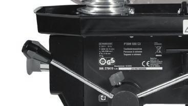
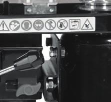
62 G
IAN 102855 BENCH PILLAR DRILL PTBM 500 A1 ΕΠΙΤΡΑΠΕΖΙΟ ΔΡΑΠΑΝΟ BENCH PILLAR DRILL TISCHBOHRMASCHINE. Μετάφραση των αυθεντικών οδηγιών λειτουργίας
 BENCH PILLAR DRILL PTBM 500 A1 BENCH PILLAR DRILL Translation of original operation manual ΕΠΙΤΡΑΠΕΖΙΟ ΔΡΑΠΑΝΟ Μετάφραση των αυθεντικών οδηγιών λειτουργίας TISCHBOHRMASCHINE Originalbetriebsanleitung IAN
 BID3333 SET Angle grinder Μετάφραση του πρωτοτύπου των οδηγιών χρήσης Owner s manual www.bormanntools.com Πληροφορίες ασφαλείας Το μηχάνημα είναι σύμφωνο με τους κανονισμούς ασφαλείας των ηλεκτρικών εργαλείων.
Περιεχόμενα / Contents
 Aερόθερμo / Fan Heater PTC-906 Περιεχόμενα / Contents GR... Σελίδες 3-8 EN... Pages 9-11 2 GR Ευχαριστούμε που επιλέξατε μια συσκευή της γκάμας θερμαντικών IZZY. Σημαντικές Οδηγίες Ασφαλείας Τα Μέρη της
ΟΔΗΓΙΕΣ ΣΥΝΑΡΜΟΛΟΓΗΣΗΣ/ ASSEMBLY INSTRUCTION ΤΟΜΜΥ ΚΡΕΒΑΤΙ/BED
 ΟΔΗΓΙΕΣ ΣΥΝΑΡΜΟΛΟΓΗΣΗΣ/ ASSEMBLY INSTRUCTION ΤΟΜΜΥ ΚΡΕΒΑΤΙ/BED 1. Παρακαλώ πολύ διαβάστε προσεκτικά τις οδηγίες πριν την συναρμολόγηση/ Please read the instructions carefully. 2. Παρακαλώ πολύ όπως ελέγξτε
Bbc7000 ΦΟΡΤΙΣΤΗΣ - ΕΚΚΙΝΗΤΗΣ ΜΠΑΤΑΡΙΑΣ. Art Nr: Owner s manual. Μετάφραση του πρωτοτύπου των οδηγιών χρήσης
 Bbc7000 ΦΟΡΤΙΣΤΗΣ - ΕΚΚΙΝΗΤΗΣ ΜΠΑΤΑΡΙΑΣ Μετάφραση του πρωτοτύπου των οδηγιών χρήσης Art Nr: 022213 Owner s manual Διαβάστε προσεχτικά όλες τις οδηγίες χρήσης και ασφάλειας πριν την λειτουργία του μηχανήματος.
Οδηγίες Λειτουργίας. Assembly Operating instructions. Montageanleitung. Απογυμνωτές PV-AZM...3. Stripping pliers PV-AZM...3.
 MA000 MA267 (de_en) (gr_en) Montageanleitung Οδηγίες Λειτουργίας Απογυμνωτής PV-AZM... για MC3, MC4 MA000 MA267 (de_en) (gr_en) Assembly Operating instructions Stripping pliers PV-AZM... for MC3 and MC4
BFN3000 ΕΠΙΤΡΑΠΕΖΙΟΣ ΑΝΕΜΙΣΤΗΡΑΣ. Owner s manual. Μετάφραση του πρωτοτύπου των οδηγιών χρήσης
 BFN3000 ΕΠΙΤΡΑΠΕΖΙΟΣ ΑΝΕΜΙΣΤΗΡΑΣ Μετάφραση του πρωτοτύπου των οδηγιών χρήσης Owner s manual www.bormanntools.com GR Οδηγίες ασφαλούς λειτουργίας 1. Τα χαρακτηριστικά της παροχής ηλεκτρικού ρεύματος θα
ES2300 Τροχιστικό αλυσίδας Owner s manual. Μετάφραση του πρωτοτύπου των οδηγιών χρήσης
 ES2300 Τροχιστικό αλυσίδας Μετάφραση του πρωτοτύπου των οδηγιών χρήσης Owner s manual Περιεχόμενα 1. Περιγραφή μηχανήματος 2. Τεχνικά χαρακτηριστικά 3. Οδηγίες ασφαλείας 4. Συναρμολόγηση 5. Συναρμολόγηση
Door Hinge replacement (Rear Left Door)
") Door Hinge replacement (Rear Left Door) We will continue the previous article by replacing the hinges of the rear left hand side door. I will use again the same procedure and means I employed during the
Door Hinge replacement (Rear Left Door) We will continue the previous article by replacing the hinges of the rear left hand side door. I will use again the same procedure and means I employed during the
Capacitors - Capacitance, Charge and Potential Difference
 Capacitors - Capacitance, Charge and Potential Difference Capacitors store electric charge. This ability to store electric charge is known as capacitance. A simple capacitor consists of 2 parallel metal
(REV:01) RYOBI 48 Volt Lawn Mower Model No. RY14110 Replacement Parts List
 RYOBI 48 Volt Lawn Mower Model No. RY14110 Replacement Parts List") 9800-86 2-0-0 (REV:0) RYOBI 48 Volt Lawn Mower Model No. RY0 Replacement Parts List RYOBI RY0 48 volt lawn mower 3 38 39 44 39 36 34 36 42 38 39 3 4 37 34 3 43 2 32 0 8 9 2 4 33 8 7 6 3 6 7 22 8 20 3 30
9800-86 2-0-0 (REV:0) RYOBI 48 Volt Lawn Mower Model No. RY0 Replacement Parts List RYOBI RY0 48 volt lawn mower 3 38 39 44 39 36 34 36 42 38 39 3 4 37 34 3 43 2 32 0 8 9 2 4 33 8 7 6 3 6 7 22 8 20 3 30
Operating Instructions and Parts Manual 16-speed Woodworking Drill Press Models JDP-15F, JDP-15B
 Operating Instructions and Parts Manual 16-speed Woodworking Drill Press Models JDP-15F, JDP-15B JET 427 New Sanford Road LaVergne, Tennessee 37086 Part No. M-716250 Ph.: 800-274-6848 Edition 1 10/2015
(REV:01) RYOBI 48 Volt Lawn Mower Model No. RY14110A Replacement Parts List
 RYOBI 48 Volt Lawn Mower Model No. RY14110A Replacement Parts List") 9000-7 9-- (REV:0) RYOBI 4 Volt Lawn Mower Model No. RY0A Replacement Parts List RYOBI RY0A 4 VOLT LAWN MOWER 3 3 39 44 39 3 34 3 42 3 39 3 4 37 34 3 43 2 0 37 2 33 32 3 9 7 22 30 4 7 3 20 9 3 2 2 27 2
9000-7 9-- (REV:0) RYOBI 4 Volt Lawn Mower Model No. RY0A Replacement Parts List RYOBI RY0A 4 VOLT LAWN MOWER 3 3 39 44 39 3 34 3 42 3 39 3 4 37 34 3 43 2 0 37 2 33 32 3 9 7 22 30 4 7 3 20 9 3 2 2 27 2
Right Rear Door. Let's now finish the door hinge saga with the right rear door
 Right Rear Door Let's now finish the door hinge saga with the right rear door You may have been already guessed my steps, so there is not much to describe in detail. Old upper one file:///c /Documents
the total number of electrons passing through the lamp.
 1. A 12 V 36 W lamp is lit to normal brightness using a 12 V car battery of negligible internal resistance. The lamp is switched on for one hour (3600 s). For the time of 1 hour, calculate (i) the energy
BID4500 ΗΛΕΚΤΡΙΚΟ ΔΡΑΠΑΝΟ. Owner s manual. Μετάφραση του πρωτοτύπου των οδηγιών χρήσης
 BID4500 ΗΛΕΚΤΡΙΚΟ ΔΡΑΠΑΝΟ Μετάφραση του πρωτοτύπου των οδηγιών χρήσης Owner s manual Σύμβολα Για να μειωθεί ο κίνδυνος τραυματισμού θα πρέπει ο χρήστης να διαβάσει το εγχειρίδιο οδηγιών χρήσης. Γενικές
ΟΔΗΓΙΕΣ ΧΡΗΣΗΣ USE INSTRUCTIONS
 ΟΔΗΓΙΕΣ ΧΡΗΣΗΣ USE INSTRUCTIONS ΤΗΛΕΦΩΝΟ ΜΕ ΑΝΑΓΝΩΡΙΣΗ ΚΛΗΣΗΣ /CORDED PHONE WITH CALLER ID ΜΟΝΤΕΛΟ/MODEL: TM09-448 DC48V Παρακαλούμε διαβάστε προσεκτικά όλες τις οδηγίες χρήσης πριν την χρήση της συσκευής
[1] P Q. Fig. 3.1
![[1] P Q. Fig. 3.1](/thumbs/79/80362156.jpg "[1] P Q. Fig. 3.1") 1 (a) Define resistance....... [1] (b) The smallest conductor within a computer processing chip can be represented as a rectangular block that is one atom high, four atoms wide and twenty atoms long. One
1 (a) Define resistance....... [1] (b) The smallest conductor within a computer processing chip can be represented as a rectangular block that is one atom high, four atoms wide and twenty atoms long. One
Bkd1300 ΚΟΛΩΝΑΤΟ ΔΡΑΠΑΝΟ. Owner s manual. Μετάφραση του πρωτοτύπου των οδηγιών χρήσης
 Bkd1300 ΚΟΛΩΝΑΤΟ ΔΡΑΠΑΝΟ Μετάφραση του πρωτοτύπου των οδηγιών χρήσης Owner s manual 2 3 GR ΟΔΗΓΙΕΣ ΑΣΦΑΛΕΙΑΣ ΓΙΑ ΗΛΕΚΤΡΙΚΑ ΕΡΓΑΛΕΙΑ ΠΡΟΣΟΧΗ! Ακολουθήστε τις ακόλουθες απλές οδηγίες ασφάλειας για να αποφύγετε
Εγκατάσταση λογισμικού και αναβάθμιση συσκευής Device software installation and software upgrade
 Για να ελέγξετε το λογισμικό που έχει τώρα η συσκευή κάντε κλικ Menu > Options > Device > About Device Versions. Στο πιο κάτω παράδειγμα η συσκευή έχει έκδοση λογισμικού 6.0.0.546 με πλατφόρμα 6.6.0.207.
Operating Instructions and Parts Manual 14-inch Woodworking Band Saw Models JWBS-14SF and JWBS-14SF-3
 Operating Instructions and Parts Manual 14-inch Woodworking Band Saw Models JWBS-14SF and JWBS-14SF-3 Model #714500 shown JET 427 New Sanford Road LaVergne, Tennessee 37086 Part No. M-714500 Ph.: 800-274-6848
ΑΚΑ ΗΜΙΑ ΕΜΠΟΡΙΚΟΥ ΝΑΥΤΙΚΟΥ ΜΑΚΕ ΟΝΙΑΣ ΣΧΟΛΗ ΜΗΧΑΝΙΚΩΝ ΠΤΥΧΙΑΚΗ ΕΡΓΑΣΙΑ ΘΕΜΑ : ΧΗΜΙΚΑ ΠΡΟΣΘΕΤΑ ΠΟΥ ΠΡΟΟΡΙΖΟΝΤΑΙ ΓΙΑ ΤΟ ΝΕΡΟ ΤΟΥ ΑΤΜΟΛΕΒΗΤΑ
 ΑΚΑ ΗΜΙΑ ΕΜΠΟΡΙΚΟΥ ΝΑΥΤΙΚΟΥ ΜΑΚΕ ΟΝΙΑΣ ΣΧΟΛΗ ΜΗΧΑΝΙΚΩΝ ΠΤΥΧΙΑΚΗ ΕΡΓΑΣΙΑ ΘΕΜΑ : ΧΗΜΙΚΑ ΠΡΟΣΘΕΤΑ ΠΟΥ ΠΡΟΟΡΙΖΟΝΤΑΙ ΓΙΑ ΤΟ ΝΕΡΟ ΤΟΥ ΑΤΜΟΛΕΒΗΤΑ ΣΠΟΥ ΑΣΤΗΣ : ΑΓΟΡΑΣΤΟΣ ΧΡΥΣΟΒΑΛΑΝΤΗΣ ΕΠΙΒΛΕΠΟΥΣΑ ΚΑΘΗΓΗΤΡΙΑ :
Operating Instructions and Parts Manual 14-inch Woodworking Band Saw Models JWBS-14SF and JWBS-14SF-3
 Operating Instructions and Parts Manual 14-inch Woodworking Band Saw Models JWBS-14SF and JWBS-14SF-3 Model #714500 shown JET 427 New Sanford Road LaVergne, Tennessee 37086 Part No. M-714500 Ph.: 800-274-6848
Instruction Execution Times
 1 C Execution Times InThisAppendix... Introduction DL330 Execution Times DL330P Execution Times DL340 Execution Times C-2 Execution Times Introduction Data Registers This appendix contains several tables
ΟΔΗΓΙΕΣ ΧΡΗΣΗΣ ΓΙΑ ΔΙΣΚΟΠΡΙΟΝΟ ΞΥΛΟΥ ΔΥΟ ΕΡΓΑΣΙΩΝ BORMANN BDX
 ΟΔΗΓΙΕΣ ΧΡΗΣΗΣ ΓΙΑ ΔΙΣΚΟΠΡΙΟΝΟ ΞΥΛΟΥ ΔΥΟ ΕΡΓΑΣΙΩΝ BORMANN BDX 2500 2 3 4 5 6 Τεχνικά χαρακτηριστικά Τάση 230V/50Hz Ισχύς 1800W Ταχύτητα 4500rpm Δυνατότητα κοπής 43mm Διάμετρος δίσκου 250mm Διαστάσεις Τραπεζιού
User s Manual / Οδηγίες Χρήσης
 User s Manual / Οδηγίες Χρήσης EUROPEAN STANDARDS Your child s safety depends on you. Proper bed rail usage cannot be assured unless you follow these instructions. DO NOT USE YOUR BED RAIL UNTILL YOU READ
INSTRUCTIONS MANUAL ΕΓΧΕΙΡΙΔΙΟ ΛΕΙΤΟΥΡΓΙΑΣ
 Model/Μοντέλο: WKH-1132 INSTRUCTIONS MANUAL ΕΓΧΕΙΡΙΔΙΟ ΛΕΙΤΟΥΡΓΙΑΣ ENGLISH General Safety Instructions Before commissioning this kettle, please read the instruction manual carefully. Please keep the instruction
ΚΥΠΡΙΑΚΗ ΕΤΑΙΡΕΙΑ ΠΛΗΡΟΦΟΡΙΚΗΣ CYPRUS COMPUTER SOCIETY ΠΑΓΚΥΠΡΙΟΣ ΜΑΘΗΤΙΚΟΣ ΔΙΑΓΩΝΙΣΜΟΣ ΠΛΗΡΟΦΟΡΙΚΗΣ 19/5/2007
 Οδηγίες: Να απαντηθούν όλες οι ερωτήσεις. Αν κάπου κάνετε κάποιες υποθέσεις να αναφερθούν στη σχετική ερώτηση. Όλα τα αρχεία που αναφέρονται στα προβλήματα βρίσκονται στον ίδιο φάκελο με το εκτελέσιμο
Εγγύηση καλής λειτουργίας
 Εγγύηση καλής λειτουργίας Τα Smartphone Bitmore συνοδεύονται από Εγγύηση Καλής Λειτουργίας Δύο (2) Ετών. Please read carefully the Παρακαλούμε διαβάστε προσεκτικά τους όρους εγγύησης που συνοδεύουν το
MS SERIES MS DESK TOP ENCLOSURE APPLICATION EXAMPLE FEATURE. Measuring instruments. Power supply equipments
 MS SERIES MS DESK TOP ENCLOSURE FEATURE Available in 176 sizes. Screws are not appeared on the surface. Usable as rack mount case with optinal mounting bracket. There are no ventilation hole for cover
VENERE. GR. Οδηγός Χρήσης EN. User Guide
 GR. Οδηγός Χρήσης EN. User Guide ΣΗΜΑΝΤΙΚΟ! ΚΡΑΤΗΣΤΕ ΓΙΑ ΜΕΛΛΟΝΤΙΚΗ ΑΝΑΦΟΡΑ: ΔΙΑΒΑΣΤΕ ΠΡΟΣΕΚΤΙΚΑ Κίνδυνος από φωτιά και άλλες πηγές έντονης θερμότητας, όπως ηλεκτρικές αντιστάσεις, υγραέριο, φωτιά κλπ,
Strain gauge and rosettes
 Strain gauge and rosettes Introduction A strain gauge is a device which is used to measure strain (deformation) on an object subjected to forces. Strain can be measured using various types of devices classified
SPEEDO AQUABEAT. Specially Designed for Aquatic Athletes and Active People
 SPEEDO AQUABEAT TM Specially Designed for Aquatic Athletes and Active People 1 2 Decrease Volume Increase Volume Reset EarphonesUSBJack Power Off / Rewind Power On / Fast Forward Goggle clip LED Status
ΟΔΗΓΙΕΣ ΕΓΚΑΤΑΣTΑΣΗΣ ΓΙΑ ΠΑΤΩΜΑ WPC INSTALLATION GUIDE FOR WPC DECKING
 1/12 ΟΔΗΓΙΕΣ ΕΓΚΑΤΑΣTΑΣΗΣ ΓΙΑ ΠΑΤΩΜΑ WPC INSTALLATION GUIDE FOR WPC DECKING Ανοίγουμε τρύπες Ø8 x 80mm στο σημείο κατασκευής, με τρυπάνι. To προτεινόμενο πλάτος και μήκος μεταξύ των 2 οπών να είναι 30-35εκ.,
MSN DESK TOP ENCLOSURE WITH STAND / CARRYING HANDLE
 MSN SERIES MSN DESK TOP ENCLOSURE WITH STAND / CARRYING HANDLE W H FEATURE Available in 176 sizes. Stand / carrying handle can be adjusted in 30 degree. Maximum load is kg. There are no ventilation hole
 BID3333 set Μετάφραση του πρωτοτύπου των οδηγιών χρήσης Owner s manual 1. Κατάλληλη χρήση Το εργαλείο αυτό είναι σχεδιασμένο για χρήση ως τρυπάνι σε μπετό, πέτρα, ξύλο, μέταλλο και πλαστικό. Ο κατασκευαστής
Surface Mount Multilayer Chip Capacitors for Commodity Solutions
 Surface Mount Multilayer Chip Capacitors for Commodity Solutions Below tables are test procedures and requirements unless specified in detail datasheet. 1) Visual and mechanical 2) Capacitance 3) Q/DF
Potential Dividers. 46 minutes. 46 marks. Page 1 of 11
 Potential Dividers 46 minutes 46 marks Page 1 of 11 Q1. In the circuit shown in the figure below, the battery, of negligible internal resistance, has an emf of 30 V. The pd across the lamp is 6.0 V and
D36-42 D46-42 D50-42 MODEL DIESEL PILE HAMMER SPARE PARTS BOOK
 MODEL D36-42 D46-42 D50-42 DIESEL PILE HAMMER SPARE PARTS BOOK Corporate Office 7032 S. 196th Street Kent, WA, USA 98032 Tel: 1-800-248-8498 Tel: 1-253-872-0141 Fax: 1-253-872-8710 2 No. Parts-No. Description
Code Breaker. TEACHER s NOTES
 TEACHER s NOTES Time: 50 minutes Learning Outcomes: To relate the genetic code to the assembly of proteins To summarize factors that lead to different types of mutations To distinguish among positive,
Modbus basic setup notes for IO-Link AL1xxx Master Block
 n Modbus has four tables/registers where data is stored along with their associated addresses. We will be using the holding registers from address 40001 to 49999 that are R/W 16 bit/word. Two tables that
department listing department name αχχουντσ ϕανε βαλικτ δδσϕηασδδη σδηφγ ασκϕηλκ τεχηνιχαλ αλαν ϕουν διξ τεχηνιχαλ ϕοην µαριανι
 She selects the option. Jenny starts with the al listing. This has employees listed within She drills down through the employee. The inferred ER sttricture relates this to the redcords in the databasee
Section 8.3 Trigonometric Equations
 99 Section 8. Trigonometric Equations Objective 1: Solve Equations Involving One Trigonometric Function. In this section and the next, we will exple how to solving equations involving trigonometric functions.
ΛΙΣΤΑ ΕΞΑΡΤΗΜΑΤΩΝ Ο ΗΓΙΕΣ ΣΥΝΑΡΜΟΛΟΓΗΣΗΣ
 ΠΟΛΥΟΡΓΑΝΟ BR300 Ο ΗΓΙΕΣ ΣΥΝΑΡΜΟΛΟΓΗΣΗΣ ΛΙΣΤΑ ΕΞΑΡΤΗΜΑΤΩΝ NUMBER DESCRIPTION QUANTITY 1 LEFT MAIN BASE FRAME 1 2 RIGHT MAIN BASE FRAME 1 3 CENTER MAIN BASE FRAME 1 4 FRONT MAIN BASE FRAME 1 5 UPRIGHT 2
ΟΔΗΓΙΕΣ ΧΡΗΣΗΣ 16 ΕΠΙΔΑΠΕΔΙΟΣ ΑΝΕΜΙΣΤΗΡΑΣ ΜΕ ΤΗΛΕΧΕΙΡΙΣΤΗΡΙΟ R-845
 ΟΔΗΓΙΕΣ ΧΡΗΣΗΣ 16 ΕΠΙΔΑΠΕΔΙΟΣ ΑΝΕΜΙΣΤΗΡΑΣ ΜΕ ΤΗΛΕΧΕΙΡΙΣΤΗΡΙΟ R-845 Ευχαριστούμε για την αγορά του ανεμιστήρα. Παρακαλούμε διαβάστε προσεκτικά τις οδηγίες χρήσης πριν θέσετε σε λειτουργία τη συσκευή. Αγαπητέ
Operating-instruction Manual ΟΔΗΓΙΕΣ ΧΡΗΣΕΩΣ
 Operating-instruction Manual ΟΔΗΓΙΕΣ ΧΡΗΣΕΩΣ 16 3 SPEED PEDESTAL FAN 16 ΑΝΕΜΙΣΤΗΡΑΣ ΟΡΘΟΣΤΑΤΗΣ 3 ΤΑΧΥΤΗΤΩΝ PLEASE READ ALL INSTRUCTIONS CAREFULLYAND KEEP FOR FUTURE USE ΠΑΡΑΚΑΛΩ ΔΙΑΒΑΣΤΕ ΤΙΣ ΟΔΗΓΙΕΣ ΧΡΗΣΗΣ
Owner s manual. Μετάφραση του πρωτοτύπου των οδηγιών χρήσης. Bdt2000 ΔΙΔΥΜΟΣ ΤΡΟΧΟΣ
 Μετάφραση του πρωτοτύπου των οδηγιών χρήσης Owner s manual Bdt2000 ΔΙΔΥΜΟΣ ΤΡΟΧΟΣ ΟΔΗΓΙΕΣ ΑΣΦΑΛΕΙΑΣ ΓΙΑ ΗΛΕΚΤΡΙΚΑ ΕΡΓΑΛΕΙΑ ΠΡΟΣΟΧΗ! Ακολουθήστε τις ακόλουθες απλές οδηγίες ασφάλειας για να αποφύγετε κίνδυνους
Bfn8000 ΑΝΕΜΙΣΤΗΡΑΣ 3 ΣΕ 1. Owner s manual. Μετάφραση του πρωτοτύπου των οδηγιών χρήσης
 Bfn8000 ΑΝΕΜΙΣΤΗΡΑΣ 3 ΣΕ 1 Μετάφραση του πρωτοτύπου των οδηγιών χρήσης Owner s manual GR Οδηγίες ασφαλείας Για την ορθή χρήση του ανεμιστήρα, την μείωση των πιθανοτήτων εκδήλωσης πυρκαγιάς, ηλεκτροπληξίας
Οδηγίες Αγοράς Ηλεκτρονικού Βιβλίου Instructions for Buying an ebook
 Οδηγίες Αγοράς Ηλεκτρονικού Βιβλίου Instructions for Buying an ebook Βήμα 1: Step 1: Βρείτε το βιβλίο που θα θέλατε να αγοράσετε και πατήστε Add to Cart, για να το προσθέσετε στο καλάθι σας. Αυτόματα θα
derivation of the Laplacian from rectangular to spherical coordinates
 derivation of the Laplacian from rectangular to spherical coordinates swapnizzle 03-03- :5:43 We begin by recognizing the familiar conversion from rectangular to spherical coordinates (note that φ is used
Precision Metal Film Fixed Resistor Axial Leaded
 Features EIA standard colour-coding Non-Flame type available Low noise and voltage coefficient Low temperature coefficient range Wide precision range in small package Too low or too high ohmic value can
Bdt1530 ΔΙΔΥΜΟΣ ΤΡΟΧΟΣ. Owner s manual. Μετάφραση του πρωτοτύπου των οδηγιών χρήσης
 Bdt1530 ΔΙΔΥΜΟΣ ΤΡΟΧΟΣ Μετάφραση του πρωτοτύπου των οδηγιών χρήσης www.bormanntools.com Owner s manual GR ΟΔΗΓΙΕΣ ΑΣΦΑΛΕΙΑΣ ΓΙΑ ΗΛΕΚΤΡΙΚΑ ΕΡΓΑΛΕΙΑ ΠΡΟΣΟΧΗ! Ακολουθήστε τις ακόλουθες απλές οδηγίες ασφάλειας
NMBTC.COM /
 Common Common Vibration Test:... Conforms to JIS C 60068-2-6, Amplitude: 1.5mm, Frequency 10 to 55 Hz, 1 hour in each of the X, Y and Z directions. Shock Test:...Conforms to JIS C 60068-2-27, Acceleration
EE512: Error Control Coding
 EE512: Error Control Coding Solution for Assignment on Finite Fields February 16, 2007 1. (a) Addition and Multiplication tables for GF (5) and GF (7) are shown in Tables 1 and 2. + 0 1 2 3 4 0 0 1 2 3
CHAPTER 25 SOLVING EQUATIONS BY ITERATIVE METHODS
 CHAPTER 5 SOLVING EQUATIONS BY ITERATIVE METHODS EXERCISE 104 Page 8 1. Find the positive root of the equation x + 3x 5 = 0, correct to 3 significant figures, using the method of bisection. Let f(x) =
BDS8000 ΤΡΙΒΕΙΟ ΓΥΨΟΣΑΝΙΔΑΣ. Owner s manual. Μετάφραση του πρωτοτύπου των οδηγιών χρήσης
 BDS8000 ΤΡΙΒΕΙΟ ΓΥΨΟΣΑΝΙΔΑΣ Μετάφραση του πρωτοτύπου των οδηγιών χρήσης Owner s manual ΔΙΑΒΑΣΤΕ ΠΡΟΣΕΧΤΙΚΑ ΤΙΣ ΟΔΗΓΙΕΣ ΧΡΗΣΗ ΠΡΙΝ ΤΗΝ ΛΕΙΤΟΥΡΓΙΑ ΤΟΥ ΜΗΧΑΝΗΜΑΤΟΣ 1. Οδηγίες ασφαλείας Σημείωση: Για να μειώσετε
Bfn7000 ΑΝΕΜΙΣΤΗΡΑΣ ΟΡΘΟΣΤΑΤΗΣ. Owner s manual. Μετάφραση του πρωτοτύπου των οδηγιών χρήσης
 Bfn7000 ΑΝΕΜΙΣΤΗΡΑΣ ΟΡΘΟΣΤΑΤΗΣ Μετάφραση του πρωτοτύπου των οδηγιών χρήσης Owner s manual GR Οδηγίες ασφαλείας Για την ορθή χρήση του ανεμιστήρα, την μείωση των πιθανοτήτων εκδήλωσης πυρκαγιάς, ηλεκτροπληξίας
Advanced Subsidiary Unit 1: Understanding and Written Response
 Write your name here Surname Other names Edexcel GE entre Number andidate Number Greek dvanced Subsidiary Unit 1: Understanding and Written Response Thursday 16 May 2013 Morning Time: 2 hours 45 minutes
MODEL D25-42 D30-42 DIESEL PILE HAMMER SPARE PARTS BOOK
 MODEL D25-42 D30-42 DIESEL PILE HAMMER SPARE PARTS BOOK Corporate Office 7032 S. 196th Street Kent, WA, USA 98032 Tel: 1-800-248-8498 Tel: 1-253-872-0141 Fax: 1-253-872-8710 2 No. Parts-No. Description
Thin Film Chip Resistors
 FEATURES PRECISE TOLERANCE AND TEMPERATURE COEFFICIENT EIA STANDARD CASE SIZES (0201 ~ 2512) LOW NOISE, THIN FILM (NiCr) CONSTRUCTION REFLOW SOLDERABLE (Pb FREE TERMINATION FINISH) Type Size EIA PowerRating
MODEL D62-42 D70-42 DIESEL PILE HAMMER SPARE PARTS BOOK
 MODEL D62-42 D70-42 DIESEL PILE HAMMER SPARE PARTS BOOK Corporate Office 7032 S. 196th Street Kent, WA, USA 98032 Tel: 1-800-248-8498 Tel: 1-253-872-0141 Fax: 1-253-872-8710 2 No. Parts-No. Description
ES Owner s manual. Μετάφραση του πρωτοτύπου των οδηγιών χρήσης
 ES2700 Μετάφραση του πρωτοτύπου των οδηγιών χρήσης Owner s manual Οδηγίες Ασφάλειας Το μηχάνημα είναι σύμφωνο με τις οδηγίες ασφάλειας των ηλεκτρικών εργαλείων. Διαβάστε τις οδηγίες πριν να ξεκινήσετε
Οδηγίες Χρήσης BWR5106
 Οδηγίες Χρήσης BWR5106 Περιγραφή εργαλείου Οι αντλίες χειρός είναι ένα εργαλείο με την ικανότητα, πιέζοντας τον λεβιέ πάνω κάτω να πρεσάρει γράσο σε μεγάλη πίεση και με την βοήθεια αυτής να γρασάρει οπού
ΦΎΛΛΟ ΔΕΔΟΜΈΝΩΝ 100/ /700 P5
 100/120 277/700 P5 OPTOTRONIC Σταθερού ρεύματος ECG για μονάδες LED ΠΕΡΙΟΧΈΣ ΕΦΑΡΜΟΓΉΣ Φωτισμός δρόμων και αστικός φωτισμός Βιομηχανία Κατάλληλο για φωτιστικά με κατηγορία προστασίας I ΠΛΕΟΝΕΚΤΉΜΑΤΑ ΠΡΟΪΌΝΤΟΣ
3.4 SUM AND DIFFERENCE FORMULAS. NOTE: cos(α+β) cos α + cos β cos(α-β) cos α -cos β
 cos α + cos β cos(α-β) cos α -cos β") 3.4 SUM AND DIFFERENCE FORMULAS Page Theorem cos(αβ cos α cos β -sin α cos(α-β cos α cos β sin α NOTE: cos(αβ cos α cos β cos(α-β cos α -cos β Proof of cos(α-β cos α cos β sin α Let s use a unit circle
3.4 SUM AND DIFFERENCE FORMULAS Page Theorem cos(αβ cos α cos β -sin α cos(α-β cos α cos β sin α NOTE: cos(αβ cos α cos β cos(α-β cos α -cos β Proof of cos(α-β cos α cos β sin α Let s use a unit circle
Phys460.nb Solution for the t-dependent Schrodinger s equation How did we find the solution? (not required)
") Phys460.nb 81 ψ n (t) is still the (same) eigenstate of H But for tdependent H. The answer is NO. 5.5.5. Solution for the tdependent Schrodinger s equation If we assume that at time t 0, the electron starts
Phys460.nb 81 ψ n (t) is still the (same) eigenstate of H But for tdependent H. The answer is NO. 5.5.5. Solution for the tdependent Schrodinger s equation If we assume that at time t 0, the electron starts
2013 REV 01 ELECTRONICS CAPACITORS. DC Applications Metallized Polypropylene Film Self Healing
 2013 REV 01 POWER EECTRONICS CAPACITORS C Applications Metallized Polypropylene Film Healing OUR MISSION: POWER EECTRONICS AN SPECIA CAPACITORS M.V. PFC CAPACITORS AN BANKS IGHTING CAPACITORS MOTOR RUN
ΟΔΗΓΙΕΣ ΧΡΗΣΗΣ ΒΡΕΦΙΚΟΥ ΑΝΑΠΗΡΙΚΟΥ ΑΜΑΞΙΔΙΟΥ / Baby s Wheelchairs User Manual
 ΟΔΗΓΙΕΣ ΧΡΗΣΗΣ ΒΡΕΦΙΚΟΥ ΑΝΑΠΗΡΙΚΟΥ ΑΜΑΞΙΔΙΟΥ / Baby s Wheelchairs User Manual 0808818 ΟΔΗΓΙΕΣ ΕΓΚΑΤΑΣΤΑΣΗΣ/SETUP INSTRUCTIONS Ανοίξτε το αμαξίδιο, τραβώντας τις λαβές, δώστε πλήρη έκταση στο αμαξίδιο τραβώντας
FM1100 FM2000 FM3000 Μύλος Ζωοτροφών
 FM1100 FM2000 FM3000 Μύλος Ζωοτροφών Μετάφραση του πρωτοτύπου των οδηγιών χρήσης Owner s manual Οδηγίες χρήσης για μύλο ζωοτροφών Διαβάστε προσεχτικά τις οδηγίες χρήσης. Η μη τήρηση των οδηγιών μπορεί
BID3333 SET Jig Saw. Art Nr: Μετάφραση του πρωτοτύπου των οδηγιών χρήσης. Owner s manual
 BID3333 SET Jig Saw Μετάφραση του πρωτοτύπου των οδηγιών χρήσης Owner s manual Art Nr: 18803 Οδηγίες ασφαλείας και προειδοποιήσεις Το μηχάνημα είναι σύμφωνο με τους κανονισμούς ασφαλείας των ηλεκτρικών
66546_mel_LED-Lichtervorhang_Content_LB6+GR.indd :56
 1 2 3 4 3 66546_mel_LED-Lichtervorhang_Content_LB6+GR.indd 3 29.04.11 13:56 Table of contents Introduction Intended Use... Page 5 Description of parts... Page 5 Delivery scope... Page 6 Technical information...
UDZ Swirl diffuser. Product facts. Quick-selection. Swirl diffuser UDZ. Product code example:
 UDZ Swirl diffuser Swirl diffuser UDZ, which is intended for installation in a ventilation duct, can be used in premises with a large volume, for example factory premises, storage areas, superstores, halls,
Quick Installation Guide
 A Installation 1 F H B E C D G 2 www.trust.com/17528/faq Quick Installation Guide C C D Freewave Wireless Audio Set 17528/ 17529 D Installation Configuration Windows XP 4 5 8 Windows 7/ Vista 6 7 9 10
Bid5500 ΚΡΟΥΣΤΙΚΟ ΔΡΑΠΑΝΟ. Owner s manual. Μετάφραση του πρωτοτύπου των οδηγιών χρήσης
 Bid5500 ΚΡΟΥΣΤΙΚΟ ΔΡΑΠΑΝΟ Μετάφραση του πρωτοτύπου των οδηγιών χρήσης Owner s manual Βασικά χαρακτηριστικά 1. Τσόκ 2. Διακόπτης ενεργοποίησης απενεργοποίησης λειτουργίας κρούσης 3. Ράβδος-στοπ βάθους διάτρησης
The challenges of non-stable predicates
 The challenges of non-stable predicates Consider a non-stable predicate Φ encoding, say, a safety property. We want to determine whether Φ holds for our program. The challenges of non-stable predicates
TILE CUTTING MACHINE PFSM 500 A1
 TILE CUTTING MACHINE PFSM 500 A1 TILE CUTTING MACHINE Translation of the original instructions ΚΟΦΤΗΣ ΠΛΑΚΙΔΙΩΝ Μετάφραση των αυθεντικών οδηγιών λειτουργίας FLIESENSCHNEIDMASCHINE Originalbetriebsanleitung
The Nottingham eprints service makes this work by researchers of the University of Nottingham available open access under the following conditions.
 Luevorasirikul, Kanokrat (2007) Body image and weight management: young people, internet advertisements and pharmacists. PhD thesis, University of Nottingham. Access from the University of Nottingham repository:
Math 6 SL Probability Distributions Practice Test Mark Scheme
 Math 6 SL Probability Distributions Practice Test Mark Scheme. (a) Note: Award A for vertical line to right of mean, A for shading to right of their vertical line. AA N (b) evidence of recognizing symmetry
 60 61 62 63 64 65 Ο Δ Η Γ Ι Ε Σ Σ Υ Ν Τ Η Ρ Η Σ Η Σ Τ Ω Ν Κ Ο Υ Φ Ω Μ Α Τ Ω Ν Ι Ν S T R U C T I N O N S C O N C E R N I N G Τ Η Ε C A S E M E N T S M A I N T E N A N C E Ο τακτικός καθαρισμός των βαμμένων
BAG1400 Γωνιακός Τροχός. Owner s manual. Μετάφραση του πρωτοτύπου των οδηγιών χρήσης
 BAG1400 Γωνιακός Τροχός Μετάφραση του πρωτοτύπου των οδηγιών χρήσης Owner s manual Τεχνικά χαρακτηριστικά Μοντέλο Ισχύς (W) Στροφές Διάμετρος Σπείρωμα (min -1 ) δίσκου (mm) BAG1400 1400 11000 125 M14 2
Οδηγίες Χρήσης ΒΡΗ1000
 Οδηγίες Χρήσης ΒΡΗ1000 Τεχνικά χαρακτηριστικά Ισχύς Ταχύτητα περιστροφής εν κενό Κτυπήματα το λεπτό Ισχύς κτυπήματος Τύπος υποδοχέα τρυπανιού και εργαλείου Μέγιστη δυνατότητα τρυπήματος Βάρος 620W 0-870
ΟΔΗΓΙΕΣ ΧΡΗΣΗΣ USE INSTRUCTIONS
 ΟΔΗΓΙΕΣ ΧΡΗΣΗΣ USE INSTRUCTIONS ΗΛΕΚΤΡΙΚΗ ΕΣΤΙΑ ΚΑΦΕ COFFEE HOT PLATE Μοντέλο / Model : ES-2308 230V~50Hz 450W Παρακαλούμε διαβάστε προσεκτικά όλες τις οδηγίες χρήσης πριν την χρήση της συσκευής και φυλάξτε
QUICKTRONIC PROFESSIONAL QTP5
 osram.com QUICKTRONIC PROFESSIONA QTP5 ECG for T5/ 16mm, T8/ 26mm, DUUX fluorescent lamps QTP5 i.e. UMIUX T5 HO ES 01 Product Features: Up to 100.000 hours lifetime 1 amp start with optimized filament
9.09. # 1. Area inside the oval limaçon r = cos θ. To graph, start with θ = 0 so r = 6. Compute dr
 9.9 #. Area inside the oval limaçon r = + cos. To graph, start with = so r =. Compute d = sin. Interesting points are where d vanishes, or at =,,, etc. For these values of we compute r:,,, and the values
1. Αφετηρία από στάση χωρίς κριτή (self start όπου πινακίδα εκκίνησης) 5 λεπτά µετά την αφετηρία σας από το TC1B KALO LIVADI OUT
 5 λεπτά µετά την αφετηρία σας από το TC1B KALO LIVADI OUT") Date: 21 October 2016 Time: 14:00 hrs Subject: BULLETIN No 3 Document No: 1.3 --------------------------------------------------------------------------------------------------------------------------------------
Date: 21 October 2016 Time: 14:00 hrs Subject: BULLETIN No 3 Document No: 1.3 --------------------------------------------------------------------------------------------------------------------------------------
Econ 2110: Fall 2008 Suggested Solutions to Problem Set 8 questions or comments to Dan Fetter 1
 Eon : Fall 8 Suggested Solutions to Problem Set 8 Email questions or omments to Dan Fetter Problem. Let X be a salar with density f(x, θ) (θx + θ) [ x ] with θ. (a) Find the most powerful level α test
2973-010L 2973-016L. Φωτιστικό αλογόνου με σφιγκτήρα. Halogen Clip Lamp. Υποδείξεις χειρισμού και ασφάλειας. Operation and Safety Notes
 2973-010L 2973-016L halogen Clip Lamp Halogen Clip Lamp Operation and Safety Notes Φωτιστικό αλογόνου με σφιγκτήρα Υποδείξεις χειρισμού και ασφάλειας Before reading, unfold the page containing the illustrations
BENCH GRINDER WITH BELT SANDER PSBS 240 B2
 BENCH GRINDER WITH BELT SANDER PSBS 240 B2 BENCH GRINDER WITH BELT SANDER Translation of original operation manual ΤΑΙΝΙΟΛΕΙΑΝΤΗΡΑΣ ΒΑΣΗΣ ΜΕ ΤΡΟΧΟ ΛΕΙΑΝΣΗΣ Μετάφραση των αυθεντικών οδηγιών λειτουργίας
W-898 Tire Changer Parts
 W-898 Tire Changer Parts 19 30 53 37 32 27 40 54 43 47 44 48 49 45 46 10 8 7 6 5 4 42 51 52 16 17 18 14 24 15 22 21 20 39 43 23 13 12 26 25 3 30 33 31 37 32 29 28 36 38 35 34 11 50 9 1 2 41 32 321 REVISION
(1) Describe the process by which mercury atoms become excited in a fluorescent tube (3)
 Describe the process by which mercury atoms become excited in a fluorescent tube (3)") Q1. (a) A fluorescent tube is filled with mercury vapour at low pressure. In order to emit electromagnetic radiation the mercury atoms must first be excited. (i) What is meant by an excited atom? (1) (ii)
Q1. (a) A fluorescent tube is filled with mercury vapour at low pressure. In order to emit electromagnetic radiation the mercury atoms must first be excited. (i) What is meant by an excited atom? (1) (ii)
2 Composition. Invertible Mappings
 Arkansas Tech University MATH 4033: Elementary Modern Algebra Dr. Marcel B. Finan Composition. Invertible Mappings In this section we discuss two procedures for creating new mappings from old ones, namely,
Δημιουργία Λογαριασμού Διαχείρισης Business Telephony Create a Management Account for Business Telephony
 Δημιουργία Λογαριασμού Διαχείρισης Business Telephony Create a Management Account for Business Telephony Ελληνικά Ι English 1/7 Δημιουργία Λογαριασμού Διαχείρισης Επιχειρηματικής Τηλεφωνίας μέσω της ιστοσελίδας
IAN Chain Sharpener FSG 85 C2. Chain Sharpener Translation of the original instructions
 Chain Sharpener FSG 85 C2 Chain Sharpener Translation of the original instructions Συσκευή ακονίσματος αλυσοπρίονου Μετάφραση των αυθεντικών οδηγιών λειτουργίας Kettenschärfgerät Originalbetriebsanleitung
C.S. 430 Assignment 6, Sample Solutions
 C.S. 430 Assignment 6, Sample Solutions Paul Liu November 15, 2007 Note that these are sample solutions only; in many cases there were many acceptable answers. 1 Reynolds Problem 10.1 1.1 Normal-order
L18VFSS10E. Instruction Manual 45.7cm/18 High Power Floor Fan. Εγχειρίδιο Οδηγιών Επιδαπεδιος Ανεμιστηρας 45.7 Εκατοστομετρο
 L18VFSS10E Instruction Manual 45.7cm/18 High Power Floor Fan Εγχειρίδιο Οδηγιών Επιδαπεδιος Ανεμιστηρας 45.7 Εκατοστομετρο GB GR Contents GB Safety Warnings... 2 Unpacking... 5 Getting to Know Your Fan...
Bfn2000 ΕΠΙΤΡΑΠΕΖΙΟΣ ΑΝΕΜΙΣΤΗΡΑΣ. Owner s manual. Μετάφραση του πρωτοτύπου των οδηγιών χρήσης
 Bfn2000 ΕΠΙΤΡΑΠΕΖΙΟΣ ΑΝΕΜΙΣΤΗΡΑΣ Μετάφραση του πρωτοτύπου των οδηγιών χρήσης Owner s manual Οδηγίες ασφαλείας Για την ορθή χρήση του ανεμιστήρα, την μείωση των πιθανοτήτων εκδήλωσης πυρκαγιάς, ηλεκτροπληξίας
Assalamu `alaikum wr. wb.
 LUMP SUM Assalamu `alaikum wr. wb. LUMP SUM Wassalamu alaikum wr. wb. Assalamu `alaikum wr. wb. LUMP SUM Wassalamu alaikum wr. wb. LUMP SUM Lump sum lump sum lump sum. lump sum fixed price lump sum lump
ΕΠΙΤΟΙΧΑ ΡΑΦΙΑ WALL UNIT
 ΕΠΙΤΟΙΧΑ ΡΑΦΙΑ WALL UNIT # # NO ΠΕΡΙΓΡΑΦΗ ΠΡΟΪΟΝΤΟΣ PRODUCT DESCRIPTION 1 ΚΟΛΩΝΑ UPRIGHT ΠΟΔΑΡΙΚΟ BASELEG 3 ΠΛΑΤΗ BACK PANEL 4 ΒΡΑΧΙΟΝΑΣ BRACKET 5 ΡΑΦΙ SHELF 6 ΚΟΡΝΙΖΑ ΤΙΜΩΝ PRICE STRIP 7 ΜΠΑΖΟ PLINTH
BSM2800 ΛΕΙΑΝΤΗΡΑΣ ΠΟΛ/ΠΛΩΝ ΕΦΑΡΜΟΓΩΝ. Owner s manual. Μετάφραση του πρωτοτύπου των οδηγιών χρήσης
 BSM2800 ΛΕΙΑΝΤΗΡΑΣ ΠΟΛ/ΠΛΩΝ ΕΦΑΡΜΟΓΩΝ Μετάφραση του πρωτοτύπου των οδηγιών χρήσης Owner s manual ΟΔΗΓΙΕΣ ΑΣΦΑΛΕΙΑΣ ΓΙΑ ΗΛΕΚΤΡΙΚΑ ΕΡΓΑΛΕΙΑ ΠΡΟΣΟΧΗ! Ακολουθήστε τις ακόλουθες απλές οδηγίες ασφάλειας για