G** TS** TS** EW** EW**
|
|
|
- Αμάλθεια Αβραμίδης
- 7 χρόνια πριν
- Προβολές:
Transcript
1 G** ** TS** TS** EW** EW**
2 Operating Instructions and Installation Contents 11. Precautions Precautions for the Service Precautions for the Static Electricity and PL Precautions for the Safety Product Specifications The Feature of Product The Feature of Product Modified items compared with Basic model The Comparative Specifications of Product Accessory and Option Specifications Accessories Filter Accessories Details for Operation Property Disassembly and Reassembly Indoor Unit Outdoor Unit Troubleshooting Setting Option Setup Method Display Error and Check Method Display Error mode Fault Diagnosis by Symptom Indoor Temperature Sensor Error When is diplayed Indoor Heat Exchanger Temperature Sensor Error When is diplayed Indoor Fan Motor Speed Detecting Error When is diplayed EEPROM Error or Option Error MPI Feedback Error When E186 is displayed No Power (completely dead)-initial diagnosis (Not displayed) When the Up/Down Louver Motor Does Not Operate. (Initial Diagnosis) (Not displayed) When the remote control is not receiving PCB Inspection Method Pre-inspection Notices Inspection Procedure Indoor Detailed Inspection Procedure Main Part Inspection Method Samsung Electronics
3 Contents 15. Exploded Views and Parts List Indoor Unit Outdoor Unit PCB Diagram and Parts List Block Diagram Ass'y Control In Indoor Main PCB Indoor Display PCB Electrical Parts List Wiring Diagram Schematic Diagram PCB Circuit Description Indoor Unit Display Reference Sheet Refrigerating Cycle Diagram Index for Model Name Pressure & Capacity mark Low Refrigerant Pressure Distribution Installation Diagram of Indoor Unit and Outdoor Unit Samsung Electronics 3
4 1. Precautions 1-1 Precautions for the Service Use the standard parts when replacing the electric parts. - Confirm the model name, rated voltage, rated current of the electric parts. Repair the disconnection of HARNESS securely when repairing the break down. - If there is any connection error, it causes an abnormal noise and incorrect operation. In case that you assemble or disassemble the products with laying it on the side, do work on the work cloth. - If not, the exterior of products can be scratched. Remove dust and foreign materials from harness, connection part, and inspection part thoroughly when repairing the break down. - It protects the danger of fire such as tracking and short. Tighten tightly the service valve of outdoor unit and the cap of charging valve with a monkey spanner. Check the assembly status of parts after repairing the break down. - It should be same as the status before repairing. 1-2 Precautions for the Static Electricity and PL As the PCB power terminal has a weakness for the static electricity, pay attention to it during the repair and measurement. - Work with insulation gloves during the repair and measurement of PCB. Check the distance between the product and the other electronic appliances such as TV, Video, and audio. It should be over 2m. - If not, it causes a bad picture quality or a noise. Repairing the products by consumer should be strictly prohibited. - There is a danger of electric shock or fire due to incorrect disassembly. Samsung Electronics 1-1
5 1-3 Precautions for the Safety Do not pull any electric wires and do not touch an auxiliary power switch with a wet hand. - There is a danger of electric shock or fire. In case any wire or power plug has been damaged, replace it to eliminate any possible danger. Do not bend the power cord by force and do not put any heavy object on the power cord. - There is a danger of electric shock or fire. Do not use multi socket. - There is a danger of electric shock or fire. Ground the product if necessary. - Be sure to ground the product if there is any danger of electric leakage due to water or moisture. Be sure to turn off the auxiliary power switch or pull out the power plug during replacement or repair of electric parts. - There is a danger of electric shock. In case the product will not be in use for a long time, the battery of remote control should be kept separately. - Leakage of inside fluid can cause break down of remote control. 1-2 Samsung Electronics
6 2. Product Specifications 2-1 The Feature of Product The Feature of Product good' sleep Mode good sleep mode can help you sleep quickly and soundly and wake up refreshed. Catechin Filter Catechin,extracted from the green tea,is contained in the filter and deactivates captured bacteria and unpleasant odors. Silver Nano Evaporator Deodorizing Filter Activated carbon is incorporated in the filter,efficiently absorbing cigarette smoke, pet odors, and other unpleasant smells, replacing them with clean,refreshing air. Anti-Bacterial Cross Fan Samsung Electronics 2-1
7 2-1-2 Modified items compared with Basic model 2-2 Samsung Electronics
8 2-1-2 Modified items compared with Basic model EWFSER EWFSER Samsung Electronics 2-3
9 2-2 The Comparative Specifications of Product 2-4 Samsung Electronics
10 2-2 The Comparative Specifications of Product Samsung Electronics 2-5
11 2-2 The Comparative Specifications of Product 2-6 Samsung Electronics
12 8
13 2-8 Samsung Electronics 2-4 Details for Operation Property
14 3. Disassembly and Reassembly Necessary Tools Item Remark +SCREW DRIVER MONKEY SPANNER Samsung Electronics 3-1
15 Operating Instructions and Installation 3-1 Indoor Unit No Parts Procedure Remark 1 PANEL-FRONT 1) Stop the driving of air conditioner and shut off main power supply. 2) Open the FRONT-GRILLE and pull out from the PANEL-FRONT. 3) Detach COVER-TERMINAL from the PANEL- FRONT.(use + Screw Driver) 4) Loosen connector wire(white) and detach the temperature sensor wire. 5) To detach the FRONT-PANEL the main frame, unfasten 2 screw at the bottom.(use + Screw Driver) 6) Take off the FRONT-PANEL,lifting up the bottom. 3-2 Samsung Electronics
16 Operating Instructions and Installation No Parts Procedure Remark 2 TRAY DRAIN 1) Loosen stepping motor wire and detach the hook of main frame. 2) To detach TRAY-DRAIN from the main frame, pull the bottom of the TRAY-DRAIN towards you. 3 CONTROL IN 1) Unfasten the earth screw.(use + Screw Driver) 2) Detach the temperature sensor and Humidity sensor. 3) Detach COVER-CONTROL from the CASE- CONTROL. 4) Loosen MPI connector wire(yellow), and MOTOR wires(white,blue). 5) Take off the CASE-CONTROL from the main frame. Samsung Electronics 3-3
")
 Loosen the terminal block wires.")


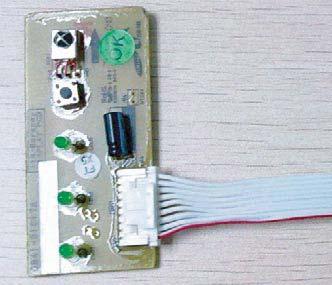
17 Operating Instructions and Installation No Parts Procedure Remark 4 PBA 1) Unfasten the screw. 2) Cut the cable tie. 3) Loosen the terminal block wires. (Total 4EA: #N(1)-2EA, #2-1EA, #3-1EA) Caution: The terminal is the locking type. So, when you separate terminals, pull pressing the button. Button 3-4 Samsung Electronics
.")
 Loosen the Humidity sensor connector(cn42). Option connector.")
 Loosen the Relay #4 blue-connector(ry71).")

18 Operating Instructions and Installation No Parts Procedure Remark 4 PBA 4) Loosen the Motor Feedback connector(cn44). Caution: When you separate the connector, pull pressing the locking button. 5) Loosen the Humidity sensor connector(cn42). Option connector. Caution: When you separate the connector, pull pressing the locking button. 6) Loosen the MPI connector(cn81). Option connector. Caution: When you separate the connector, pull pressing the locking button. 7) Loosen the Relay #4 blue-connector(ry71). Caution: The terminal is locking type. So, when you separate terminals, pull pressing the button. Button Samsung Electronics 3-5
.")


 Take off the main PBA from the ASS Y Control in.")
19 Operating Instructions and Installation No Parts Procedure Remark 4 PBA 8) Loosen the Relay #3 red-connector(ry71). Caution: The terminal is locking type. So, when you separate terminals, pull pressing the button. Button 9) Loosen the Step motor connector. Caution: When you separate the connector, pull pressing the locking button. 10) Loosen the Thermistor wire connector(cn43). Caution: When you take off the PBA, don t touch the components. Please hold the PBA both side. 11) Loosen the Motor connector(cn71). Caution: When you separate the connector, pull pressing the locking button. 12) Take off the main PBA from the ASS Y Control in. Caution: When you take off the PBA, don t touch the components. Please hold the PBA both side. 3-6 Samsung Electronics
20 Operating Instructions and Installation No Parts Procedure Remark 5 EVAPORATOR 1) Unfasten the screw at the right side. (use + Screw Driver) 2) Unfasten the screw at the left side. (use + Screw Driver) 3) Detach the HOLDER PIPE. 4) Take off the EVAPORATOR from the main frame. Samsung Electronics 3-7
21 Operating Instructions and Installation No Parts Procedure Remark 6 FAN MOTOR & CROSS FAN 1) Unfasten the screw in the HOLDER-EVAP on the left side of evaporator.(use + Screw Driver) 2) unfasten the 3 points screws in the CASE- CONTROL, and then detach the CASE. (use + Screw Driver) 3) unfasten the screw a little.(use + Screw Driver) 4) Lift up the evaporator slightly and pull the CROSS-FAN to the left side. 3-8 Samsung Electronics


22 3-2 Outdoor Unit Operating Instructions and Installation No Parts Procedure Remark 1 Common Work 1) Loosen 2 fixing screws and separate the Cover Terminal. 2) Loosen 2 fixing screws and separate the Cover Control. 3) Separate the connection wire from the Terminal Block. 4) Loosen 6 fixing screws and separate the Cabinet Front. 5) Loosen 1 fixing screw of Ass y E-part. 6) Loosen 12 fixing screws and separate the Cabinet-Side Samsung Electronics 3-9
 Remove the Nut Flange. (Turn to the clockwise) 2) Separate the Fan.")
 Loosen 2 fixing screws and separate the Motor Bracket from the Base.")
 Disassemble the inlet and outlet pipe by welding.")

 Open the Terminal Cover of Compressor and unscrew the")
23 Operating Instructions and Installation No Parts Procedure Remark 2 Fan & Motor 1) Remove the Nut Flange. (Turn to the clockwise) 2) Separate the Fan. 3) Loosen 4 fixing screws to separate the Motor. 4) Loosen 2 fixing screws and separate the Motor Bracket from the Base. 3 Heat Exchanger 1) Loosen 2 fixing screws of left and right side. 2) Disassemble the inlet and outlet pipe by welding. 3) Separate the Heat Exchanger. Before you disassemble the pipes and Condenser, be sure that there should be no refrigerant remained in the unit. 4 Compressor 1) Open the Terminal Cover of Compressor and unscrew the Connection Terminal. 2) Disassemble the inlet and outlet pipe of Compressor by welding. 3) Loosen 3 bolts of the lower part. 4) Separate the Compressor Samsung Electronics
24 4. Troubleshooting 4-1 Setting Option Setup Method Samsung Electronics 4-1
25 4-1 Setting Option Setup Method(continue) 4-2 Samsung Electronics
26 Samsung Electronics 4-3
27 OPTION ITEMS REMOCON MODEL SEG1 SEG2 SEG3 SEG4 SEG5 SEG6 SEG7 SEG8 SEG9 SEG10 SEG11 SEG C AQ09EWFSER SEG13 SEG14 SEG15 SEG16 SEG17 SEG18 SEG19 SEG20 SEG21 SEG22 SEG23 SEG MODEL REMOCON AQ12EWFSER SEG1 SEG2 SEG3 SEG4 SEG5 SEG6 SEG7 SEG8 SEG9 SEG10 SEG11 SEG A B SEG13 SEG14 SEG15 SEG16 SEG17 SEG18 SEG19 SEG20 SEG21 SEG22 SEG23 SEG Display Error and Check Method Display Error mode Error Mode AS09/12/18E ** AS09/12/18 U,R ** Cause 7-SEG OPRATION TIMER SMART SAVER INDOOR TEMPERATURE SENSOR ERROR INDOOR HEAT EXCHANGER TEMPERATURE SENSOR ERROR INDOOR FAN MOTOR SPEED DETECTING ERROR E162,LED BLINKING EEPROM ERROR (LED RANDOM BLINKING) 7-SEG,LED BLINKING OPTION ERROR (LED RANDOM BLINKING) NO USED HUMIDITY SENSOR ERROR(IN TEST MODE) MPI FEED BACK ERROR LED ON LED OFF LED BLINKING " E162 " Error is displayed only in test mode. So, if you want to check,please push the power button of indoor unit. Samsung Electronics 4-4
28 4-3 Fault Diagnosis by Symptom Indoor Temperature Sensor Error When is diplayed 1. Checklist : 1) Is the indoor units temperature sensor connected correctly? 2. Troubleshooting procedure Detach the assembly sensor from the ASS Y PCB CN43 connector and measure the sensor resistance of #1 and #2 with an ohmmeter (tester). Is the sensor resistance value 10KΩ ±3% at the room temperature of 25 C? Yes No ASS Y Sensor Replace SENSOR Resistance Value : 20 C-12.09kΩ 30 C-8.31kΩ 35 C-6.94kΩ 40 C-5.83kΩ Connect the sensor to CN43, supply power, and measure the voltage of #1 and #2 of the CN43 connector. Below 0.5V? Yes Poor ASS Y PCB Replace No Over 4.9V? Yes Poor ASS Y PCB Replace No MICOM Error or Connector(CN43) check 4-5 Samsung Electronics
29 4-3-2 Indoor Heat Exchanger Temperature Sensor Error When is diplayed 1. Checklist : 1) Is the indoor units temperature sensor connected correctly? 2. Troubleshooting procedure Detach the assembly sensor from the ASS Y PCB CN43 connector and measure the sensor resistance of #3 and #4 with an ohmmeter (tester). Is the sensor resistance value 10KΩ ±3% at the room temperature of 25 C? Yes No ASS Y Sensor Replace SENSOR Resistance Value : 20 C-12.09kΩ 30 C-8.31kΩ 35 C-6.94kΩ 40 C-5.83kΩ Connect the sensor to CN43, supply power, and measure the voltage of #3 and #4 of the CN43 connector. Below 0.5V? Yes Poor ASS Y PCB Replace No Over 4.9V? Yes Poor ASS Y PCB Replace No MICOM Error or Connector(CN43) check Samsung Electronics 4-6
30 4-3-3 Indoor Fan Motor Speed Detecting Error When is diplayed 1. Checklist : 1) Is the indoor unit fan motor properly connected with the connector (CN72)? 2) Is the AC voltage correct? 3) Is HALL IC in indoor fan motor properly connected with the connector (CN44)? 4) Is the running capacitor (CR71) properly connected with PCB board? 2. Troubleshooting procedure After unplugging out the power cord should be reconnected within 5 seconds. Yes Does the OPERATION lamp blink? No Check as in the procedure No power parts Yes Does the Solid State Relay(SS71) work properly? No Micom is out of order. Micom should be replaced Test rod location + - Normal Voltage SS71- SS71-12V Yes Is the supply voltage of the fan motor sufficient? No PCB is out of order. PCB should be replaced. PCB CN72 Test rod location Condition Normal Voltage pin #3 and #5 Fan operate About AC 180V Yes Motor Fan-Capacitor is out of order Replace Motor Fan-Capacitor Fan motor is out of order. Fan motor should be replaced. 4-7 Samsung Electronics
31 4-3-4 EEPROM Error or Option Error 1. Checklist : 1) If all lamps of Indoor unit are blinking or E162 is displayed,plug out,plug in power plug again and press ON/OFF key to retry. 2) If the unit is not working properly or all lamps are continuously blinking or E162 is displayed after resetting the option code, see if the correct option code is set up for its model. 3) Nevertheless, if all lamps are blinking or E162 is displayed, exchange the main PBA MPI Feedback Error When E186 is displayed 1. Checklist : 1) Is the mpi connector properly connected with the connector(cn81)? 2. Troubleshooting procedure After unplugging out the power cord should be reconnected within 5 seconds Yes Does the Operation Lamp blink? No Check as in the procedure "No power parts" Yes Press the mpi button Yes E186 is displayed? No Normal No Measure the voltage of #4 of the CN81 connector and #2 of the CN44 connector. Below 11V? Yes Poor MPI Replace No Poor Ass'y PCB Replace Samsung Electronics 4-8
32 4-3-6 No Power (completely dead)-initial diagnosis (Not displayed) 1. Checklist : 1) Is input voltage normal? 2) Is AC power linked correctly? 3) Is input voltage of DC regulator IC KA7805 (IC02) normal? (11VDC-12.5VDC) 4) Is output voltage of DC regulator IC KA7805 (IC02) normal? (4.5VDC-5.5VDC) 2. Troubleshooting procedure Unplug the power cord and plug it after 30 seconds Press the Power Button on the remote control unit to operate the air conditioner operate Check the display board does not operate Check the indoor unit control board Yes Check whether 2 wires of power cord are connected correctly to the terminal block and control board. No Reconnect wires correctly Yes Check whether the fuse on the control board is normal. FUSE(F701) : T3.15[A]/250[V] or T2.5[A]/250[V] No Replace fuse Yes Check the output of SMPS on the control board. Input power: AC230±15%[V] IC02 Input: DC12[V] IC02 output: DC5[V] No PCB should be replaced Yes Check the setting temperature 4-9 Samsung Electronics
33 4-3-7 When the Up/Down Louver Motor Does Not Operate. (Initial Diagnosis) (Not displayed) 1. Checklist : 1) Is input voltage normal? 2) Is the Up/Down louver motor properly connected with the connector (CN61)? 2. Troubleshooting procedure Unplug the power cord and plug it after 30 seconds Does the operation lamp blink? No Check as in the procedure No Power. Yes Does operation start when swing button of the remote control unit pushed? Yes Normal No Voltage at pin #58~#61 of micom (IC04) change?(squarewave) No Micom (IC04) is faulty. Yes Voltage at pin #2 ~ #5 of CN61(motor connector) change?(squarewave) No Driver IC05 (ULN2003A) is faulty. Yes Up/Down louver motor is faulty When the remote control is not receiving 1. Check if the connector was normally assembled. 2. Put the set in operation and check the voltage of No. 7(+) and No. 5(-) of the main PCB CN91 while operating the remote control. When the voltage descends below 3V, the assembly module PCB is normal and the main PCB is poor. Then replace the main PCB. 3. Replace the assembly display PCB because the module PCB is poor if the voltage between No. 7~5 of CN91 maintains 5V after the remote control starts operation. Samsung Electronics 4-10
34 4-4 PCB Inspection Method Pre-inspection Notices 1. Check if you pulled out the AC power plug when you eliminate the PCB or front panel. 2. Don t hold the PCB side not impose excessive force on it to eliminate the PCB. 3. Don t pull the lead wire but hold the whole housing to connect or disconnect a connector to the PCB Inspection Procedure 1. Check connector connection and peeling of PCB or bronze coating pattern when you think the PCB is broken. 2. The PCB is composed of the 2 parts. 1. Indoor Main PCB Part : MICOM and surrounding circuit, relay, room fan motor driving circuit and control circuit, sensor driving circuit, power circuit of DC12V and DC5V, and buzzer driving circuit. 1. Display part : LED lamp, Switch, Remocon module Indoor Detailed Inspection Procedure No Procedure Inspection Method Cause 1 Plug out and pull the PCB out of the electronic box. Check the PCB fuse. 2 Supply power. If the operating lamp twinkles at this time, the above 1)~3) have no relation. 1) Is the fuse disconnected? Over current Indoor Fan Motor Short AC Part Pattern Short of the MAIN PCB Checking the power voltage. 1) Is the BD71 input voltage AC200V~AC240V? Power Cord is fault, Fuse open. Wrong Power Cable Wiring, AC Part is faulty. 2) Is the voltage between both terminals of the C109 on the 2 side of the transformer DC12V ±0.5V? Switching Trans or Power Circuit is faulty 3) Is the voltage between both terminals of OUT and GND of IC02(KA7805) DC5V ±0.5V? Power Circuit is faulty, Load Short 3 Press the ON/OFF button. Checking the power voltage. 4 Press the ON/OFF button. 1. FAN Speed [High] 2. Continuous Operation 1) Is the voltage over AC180V being imposed on 1) terminal #3 and #5 of the fan motor connector(cn72)? 2) Check the voltage of both terminals of terminal block 1 and N(1) after 3 minute operation.: AC220V 1) Is the voltage over AC180V being imposed on 1) terminal #3 and #5 of the fan motor connector(cn72)? Fan Motor of the indoor is faulty Relay(RY71) Contact is faulty Fan Motor of the indoor is faulty 2) The fan motor of the indoor unit doesn t run. Fan Motor Connector(CN72) is faulty 3) The power voltage between terminal #3 and #5 of the connector(cn72) is 0V. ASS Y Main PCB is faulty Connection is faulty 4-11 Samsung Electronics
35 4-5 Main Part Inspection Method Part Breakdown Inspection Method Room Temperature Sensor Measure resistance with a tester Normal At the normal temperature 37kΩ~ 8.3kΩ(-7 C~+30 C). Abnormal, 0Ω... Open or Short Room Fan Motor Measure the resistance between terminals of the connector (CN72) with a tester. Normal At the normal temperature (10 C ~ 30 C) Compare terminal Resistance Remark STEP MOTOR Red-Pink,Yel,Blu,Org 120±7% GRILLE STEP MOTOR Red-Pink,Yel,Blu,Org 300±7% BLADE FAN MOTOR Yellow, Blue 385Ω±10% main Yellow, Red 388Ω±10% sub Abnormal, 0Ω... Open or Short Stepping Motor Measure the resistance between the red wire and each terminal wire with a tester. Normal Abnormal About 300Ω at the normal temperature (20 C ~ 30 C), 0Ω... Open or Short Samsung Electronics 4-12
36 Exploded and Parts OperatingViews Instructions andlist Installation 5. Exploded Views and Parts List 5-1 Indoor Unit AQ09***/AQ12*** 5-1 Samsung Electronics
37 Exploded Views and Parts List Parts List Samsung Electronics 5-2
38 Exploded Views and Parts List Parts List 5-3 Samsung Electronics
39 Exploded Views and Parts List Parts List Samsung Electronics 5-4
40 Exploded Views and Parts List
41 Exploded Views and Parts List Parts List Samsung Electronics 5-6

42 5-2 Outdoor Unit Exploded Views and Parts List AQ09**** AQ12**** 5-7 Samsung Electronics
43 Exploded Views and Parts List 8
44 6. PCB Diagram and Parts List 6-1. Block Diagram Ass'y Control In Samsung Electronics 6-1
45 Indoor MAIN PCB 6-2 Samsung Electronics


46 Indoor Display PCB Samsung Electronics 6-3
47 6-2. Electrical Part List Ass'y Control In PCB 6-4 Samsung Electronics
48 MAIN PCB NO CODE DESC_SPEC PARA1 PARA2 LOCATION BLOCK DB A DB D DB F SA/SNA 1 DB A PCB90*120mm,FR-1 PCB MAIN PCB PCB SNA BOX,4P,1R,2mm,STRAIGHT,SN,WHT SMW200-04P CONNECT CN SNA Kohm,1%,1/10W,TP, Kohm 1608 R-CHIP R SNA Kohm,1%,1/10W,TP, Kohm 1608 R-CHIP R SNA ohm,5%,1/10W,TP, ohm 1608 R-CHIP R SNA ohm,5%,1/10W,TP, ohm 1608 R-CHIP R SNA nF,10%,50V,X7R,TP,100nF 100nF 1608 C-CHIP C SNA nF,10%,50V,X7R,TP,100nF 100nF 1608 C-CHIP C SNA AT24C08BN,8Kbit,1Kx8,SOP,8P,4.9x3AT24C08BN,8Kbit IC-EEPROM IC SNA Kohm,5%,1/10W,TP, Kohm 1608 R-CHIP R SNA EEPROM Kohm,5%,1/10W,TP, Kohm 1608 R-CHIP R SNA Kohm,5%,1/10W,TP, Kohm 1608 R-CHIP R SNA BUZZER-PIEZO;85DB,-,-,2KHZ,- CBE2220BPC / TDP-2020P BUZZER BZ SNA R-CHIP;330ohm,5%,1/10W,TP, J 1608 R-CHIP R SNA BUZZER R-CHIP;330ohm,5%,1/10W,TP, J 1608 R-CHIP R SNA TR-SMALL SIGNAL;2SC2412K,NPN,2 2SC2412K TR-SMALL SIGNQ SNA SMW AC CONNECT CN SNA R-CHIP;1Kohm,5%,1/10W,TP,1608 1K-J R-CHIP R SNA R-CHIP;6.8Kohm,5%,1/10W,TP, K-J R-CHIP R SNA AC R-CHIP;1Kohm,5%,1/10W,TP,1608 1K-J R-CHIP R SNA TR-SMALL SIGNAL;2SC2412K,NPN,2 2SC2412K TR-SMALL SIGNQ SNA C-CER,CHIP;10nF,10%,50V,X7R,TP,110nF C-CHIP C SNA TR-ARRAY;2003,NPN,7,1W,SOP-16,SULN2003D013TR TR-ARRAY IC SNA C-CER,CHIP;100nF,10%,50V,X7R,TP,100nF,1608 C-CHIP C SNA SMW STEP MOTOR CONNECTOR CONNECT CN SNA nF,10%,50V,X7R,TP,100nF 100nF 1608 C-CER,CHIP C SNA PHOTO-COUPLER TLP181-GRH-TPL PHOTO-COUPLEPC SNA R-CHIP 4.7K-J R-CHIP R SNA R-CHIP 1Kohm,5% R-CHIP R SNA SMW DOWNLOAD CONNECT CONNECT CN SNA nF,10%,50V,X7R,TP, nF,1608 C-CHIP C SNA nF,10%,50V,X7R,TP, nF,1608 C-CHIP C SNA Kohm,5%,1/10W,TP, Kohm 1608 R-CHIP R SNA DOWNLOAD Kohm,5%,1/10W,TP, Kohm 1608 R-CHIP R SNA Kohm,5% 1.0Kohm 1608 R-CHIP R SNA R-CHIP;1Kohm,5%,1/4W,TP, Kohm 3216 R-CHIP R SNA Kohm,5%,1/10W,TP, Kohm 1608 R-CHIP R SNA IC-VOL. DETECTOR KIA7033AT,TSM,3P RESET IC IC06 RESET SNA Kohm,5% 1.0Kohm 1608 R-CHIP R SNA nF,10%,50V,X7R,TP,100nF 100nF 1608 C-CHIP C SNA R-CHIP;1Mohm,5%,1/10W,TP,1608 1Mohm,1608 R-CHIP R SNA RESONATOR-CERAMIC;10MHZ,0.5%10MHZ RESONATOR-CEX SNA 43 DB A MICOM ASSY-MIC IC SNA 44 DB A IC MICOM S3F84VBXZZ-QT8B IC MICOM IC SNA nF,10%,50V,X7R,TP, nF,1608 C-CHIP C SNA nF,10%,50V,X7R,TP,100nF 100nF 1608 C-CHIP C SNA nF,10%,50V,X7R,TP,100nF 100nF 1608 C-CHIP C SNA RELAY-POWER;12V,0.9W,25000mA,SPST,20mS,10mS RELAY RY71 COMP SNA AC MOTOR CONNECT YW396-05AV CONNECT CN SNA AC MOTOR SSR AQG22212 SSR SS SNA Kohm,5%,1/8W,AA,TP,1.8x3.2mm R-CARBON R SNA R-CHIP;47Kohm,5%,1/10W,TP, Kohm 1608 R-CHIP R902 DISPLAY SNA C-CER,CHIP;1nF,10%,50V,X7R,TP,161nF 1608 C-CHIP C SNA VARISTOR;680V,4500A,17.5x6.5mm,TINR14D681 5x6 5mm TINR14D681 / GNR14D681K,,7.5mm7 VARISTOR VA SNA 55 DB A VARISTOR CAP VARISTOR-CAP VA71-CAP SNA nF,10%,275V 12.5X6X12.0 C-FILM XC SNA 57 DB A COIL CHOKE;JL mH JL mH COIL CHOKE FT SNA FUSE-RADIAL LEAD;250V,1A,TIME-L LT H FUSE-RADIAL L F SNA DIODE-BRIDGE;DF06S,600V,1A,SMDDF06S DIODE-BRIDGE BD SNA Kohm,5%,2W,AA,TP,4.3x12mm R-METAL OXIDER SNA C-CERAMIC,DISC 1NF,10%2KV C-CERAMIC C SNA R-CHIP;33ohm,5%,1/8W,TP, J R-CHIP R SNA DIODE-RECTIFIER;1N4007,1KV,1A,D 1N4007 DIODE-RECTIFIED SNA DIODE-RECTIFIER;ES1D,200V,1A,DOES1D 200V/1A D SNA ES2D,200V,2A,SMB,TP 200V,2A D SNA C-CERAMIC,DISC 2.2nF 400V C SNA C-CERAMIC,DISC 2.2nF 400V C SNA C-AL 1000uF,20%,25V,GP,TP,10x20,5mm C-AL C SNA nF,10%,50V,X7R,TP,100nF 100nF 1608 C-CER,CHIP C SNA C-AL 220uF,20%,16V,GP,TP,8x11.5,5 C-AL C SNA SMPS nF,10%,50V,X7R,TP,100nF 100nF 1608 C-CER,CHIP C SNA nF,10%,50V,X7R,TP,100nF 100nF 1608 C-CER,CHIP C SNA nF,10%,50V,X7R,TP,100nF 100nF 1608 C-CER,CHIP C SNA C-AL 47uF,20%,25V,GP,TP,5x11,5 C-AL C SNA C-AL 10uF,20%,50V,GP,TP,5x11,5 C-AL C SNA ohm,5%,1/8W,TP, ohm2012 R-CHIP R SNA ohm,5%,1/10W,TP, ohm1608 R-CHIP R SNA Kohm,5%,1/10W,TP, Kohm1608 R SNA R-CHIP 470-J 1/10W, R SNA IC-PWM CONTROLLER TOP253PN,DIP,7P,6.35x9.57mm,PLAS IC SNA 81 DB A TRANS ST SNA PHOTO-COUPLER;TR, %,200 TLP181-GB PC SNA TR-DIGITAL DTC114EKA 200mW Q SNA DIODE-ZENER BZX84-C11 11V/350mW ZD SNA DIODE-ZENER BZX84C5V6 5.6V/225mW ZD SNA 86 DB A 2 PIN HARNESS CN SNA AC MOTOR CONNECT YW396-05AV BLU CN SNA R-CHIP 0ohm,5%,1/4W,TP,3216 JUMPER WIRE,RJ SNA JUMPER WIRE JUMPER WIRE J SNA JUMPER WIRE JUMPER WIRE J SNA JUMPER WIRE JUMPER WIRE J SNA JUMPER WIRE JUMPER WIRE J SNA JUMPER WIRE JUMPER WIRE J SNA JUMPER WIRE JUMPER WIRE J SNA JUMPER WIRE JUMPER WIRE J SNA JUMPER WIRE JUMPER WIRE J SNA JUMPER WIRE JUMPER WIRE J SNA R-CHIP 0ohm,5%,1/4W,TP,3216 JUMPER WIRE,RJ SNA JUMPER WIRE JUMPER WIRE J SNA JUMPER WIRE JUMPER WIRE J SNA JUMPER WIRE JUMPER WIRE J SNA JUMPER WIRE JUMPER WIRE J SNA JUMPER WIRE JUMPER WIRE J SNA R-CHIP 0ohm,5%,1/4W,TP,3216 JUMPER WIRE,RJ18 RJ SNA R-CHIP 0ohm,5%,1/4W,TP,3216 JUMPER WIRE,RJ SNA JUMPER WIRE JUMPER WIRE J SNA R-CHIP 0ohm,5%,1/4W,TP,3216 JUMPER WIRE,RJ SNA JUMPER WIRE JUMPER WIRE J SNA JUMPER WIRE JUMPER WIRE J SNA R-CHIP 0ohm,5%,1/4W,TP,3216 JUMPER WIRE,RJ SNA JUMPER WIRE JUMPER WIRE J SNA R-CHIP 0ohm,5%,1/4W,TP,3216 JUMPER WIRE,RJ SNA R-CHIP 0ohm,5%,1/4W,TP,3216 JUMPER WIRE,RJ SNA R-CHIP 0ohm,5%,1/4W,TP,3216 JUMPER WIRE,RJ SNA JUMPER WIRE JUMPER WIRE J SNA R-CHIP 0ohm,5%,1/4W,TP,3216 JUMPER WIRE,RJ SNA JUMPER WIRE JUMPER WIRE J SNA JUMPER WIRE JUMPER WIRE J SNA JUMPER WIRE JUMPER WIRE J SNA JUMPER WIRE JUMPER WIRE J SNA EYELET Φ3.0 EYELET RY SNA EYELET Φ3.0 EYELET RY SNA EYELET Φ3.0 EYELET RY SNA EYELET Φ3.0 EYELET RY SNA EYELET Φ3.0 EYELET CN SNA EYELET Φ3.0 EYELET CN SNA EYELET Φ3.0 EYELET CN SNA EYELET Φ3.0 EYELET CN SNA EYELET EYELET Φ2.2 EYELET F SNA EYELET Φ2.2 EYELET F SNA EYELET Φ2.2 EYELET CR SNA EYELET Φ2.2 EYELET CR SNA EYELET Φ2.2 EYELET C SNA EYELET Φ2.2 EYELET C SNA EYELET Φ2.2 EYELET C SNA EYELET Φ2.2 EYELET C SNA IC-POSI.FIXED REG. NJM7805,TO-220F,3P,-,PLASTIC,4. 1.5A IC SNA IC-POSI.FIXED REG. 7805,TO-220,3P,-,PLASTIC,4.8/5 1.0A IC SNA IC-POSI.FIXED REG. KA78L05AZTA 0.1A IC SNA HEADER-BOARD TO CABLE;BOX,4P SMW YEL CN81 SPI SNA R-COMPOSITION 12M-J 1/2W R SNA AGND GAN R-COMPOSITION 12M-J 1/2W R SNA HEADER-BOARD TO CABLE;BOX,3P SMW NTR CN SNA R-CHIP;330ohm,5%,1/10W,TP, J 1/10W,1608 R SNA C-CER,CHIP;100nF,10%,50V,X7R,TP,100nF 50V,1608 C SNA THERMISTOR-NTC NTC-22D-7(F) 1.4A/3100K NTC SNA NTC JUMPER WIRE JUMP NTC SNA nF,10%,275V 12.5X6X12.0 XC71 EMI SNA RELAY-MINIATURE;12Vdc,200mW,30PCJ-112D3MH,501X 12Vdc,3A RY74 POWER SAVE SNA JUMPER WIRE JUMP RY SNA DIODE-SWITCHING 1N4148WS,75V,150mA,SOD-323,TP D SNA TR-DIGITAL DTC114EKA 200mW Q SNA SMW DISPLAY CONNECT WHT CN91(8PIN) SNA DISPLAY SMW DISPLAY CONNECT WHT CN91(9PIN) SNA SSR AQG Vdc/2A SS72 SSR SNA Mohm,5%,1/4W,TP,3216 1Mohm,3216 R-CHIP R SNA Mohm,5%,1/4W,TP,3216 1Mohm,3216 R-CHIP R SNA Mohm,5%,1/4W,TP,3216 1Mohm,3216 R-CHIP R SNA Mohm,1%,1/4W,TP, Mohm,3216 R-CHIP R SNA ohm,5%,1/4W,TP,3216 0ohm,3216 R-CHIP R SNA V,2.5A,TIME-LAG,CERAMIC-TUBE250V,2.5A F701 FUSE SNA V,3.15A,TIME-LAG,CERAMIC, V,3.15A F SNA uF,20%,450V,GP,TP,16x31.5mm,5mm C102( SNA uF,20%,450V,GP,TP,16x31.5mm,5mm C101( SNA uF,20%,500V,TP,12.5x20mm,5mm C101-1( SNA R-CARBON 0ohm,5%,1/4W,AA,TP,2.4x6.4mm J1( SNA RELAY-MINIATURE;12Vdc,200mW,30PCJ-112D3MH,501X 12Vdc,3A RY SNA DIODE-SWITCHING 1N4148WS,75V,150mA,SOD-323,TP D601 4-WAY SNA TR-DIGITAL DTC114EKA Q SNA RELAY-MINIATURE;12Vdc,200mW,30PCJ-112D3MH,501X 12Vdc,3A RY SNA DIODE-SWITCHING 1N4148WS,75V,150mA,SOD-323,TP D701 OUT FAN SNA TR-DIGITAL DTC114EKA Q SNA C-FILM,LEAD-PPF 1.2uF 450V CR SNA C-FILM,LEAD-PPF 2.0uF 450V CR SNA C-FILM,LEAD-PPF 4.0uF 450V CR SNA R-METAL OXIDE(S) 12Kohm,5%,2W,AA,TP,4x12mm R SNA R-METAL OXIDE(S) 12Kohm,5%,2W,AF,TP,3.9x10mm R SNA R-METAL OXIDE(S) 24Kohm,5%,2W,AA,TP 4x11mm R SNA R-METAL OXIDE(S) 24Kohm,5%,2W,AA,TP 4x12mm R SNA Samsung Electronics 6-5
49 Display PCB NO REF CODE DESC_SPEC VENDOR DB A DB A DB B 1 C C-CER,CHIP;100nF,10%,50V,X7R, WALSIN 2 C C-CER,CHIP;100nF,10%,50V,X7R, WALSIN 3 C C-CER,CHIP;1nF,10%,50V,X7R, WALSIN 4 C uF,20%,25V,GP,TP,5x11,5 1 1 SAMY 5 R R-CHIP;4.7Kohm,5%,1/10W,TP, UNI-OHM 6 R R-CHIP;10Kohm,5%,1/10W,TP, UNI-OHM 7 R R-CHIP;47ohm,5%,1/10W,TP, UNI-OHM 8 R04 R -CHIP; 1 Kohm, 5 %, 1 /4W, T P, UNI-OHM 9 R05 R-CHIP;1Kohm,5%,1/4W,TP, UNI-OHM 10 R06 R-CHIP;1Kohm,5%,1/4W,TP, UNI-OHM 11 R07 R -CHIP; 1 Kohm, 5 %, 1 /4W, T P, UNI-OHM 12 R08 R-CHIP;1Kohm,5%,1/4W,TP, UNI-OHM 13 R09 R-CHIP;1Kohm,5%,1/4W,TP, UNI-OHM 14 J JUMPER J JUMPER J JUMPER J JUMPER J JUMPER J JUMPER LED ROUND,GRN,3 PI,573mm,3.0x5.0mm 0 1 DIGITECH 21 LED ROUND,GRN,3 PI,573mm,3.0x5.1mm 1 1 DIGITECH 22 LED ROUND,GRN,3 PI,573mm,3.0x5.2mm 1 1 DIGITECH 23 LED ROUND,GRN,3 PI,573mm,3.0x5.0mm 1 0 DIGITECH 24 SW V,50mA,160gf,6.1x6.1x5.0mm 1 1 HUAJIE 25 D DIODE-SWITCHING;RLS4148,75V,150mA,LL SEMTECH 26 IC HF10AP (16.4mm) 1 1 AUK 27 Q TR,FJV3102RMTF,NPN,200MW,10K/10K,SOT- 1 1 KEC 28 Q TR,FJV3102RMTF,NPN,200MW,10K/10K,SOT- 1 1 KEC 29 Q TR,FJV3102RMTF,NPN,200MW,10K/10K,SOT- 1 1 KEC 30 CN01 DB B PCB 7PIN, 9 PIN 200± JIULI 30 CN01 DB D PCB 7PIN, 9 PIN 200± JIULI 30 CN SMAW200-07,WHT 1 0 JIULI 30 CN SMAW200-07,WHT 0 1 JIULI 31 PCB BOARD DB A FR-1,T1.6,Vivaldi VE Display 1 1 DAZHAN 32 CASE-PCB DB A CASE PCB 1 X YAJING/ YUEFE 33 BUTTON-POWE DB A BUTTON POWER CASE 1 X HENGMA/YUEF 30 CN01 DB F DISPLAY TO MAIN 200mm 1 0 JIULI 6-6 Samsung Electronics
50 NO REF CODE DESC_SPEC PARA1 PARA2 Deluxe MPI Lamp Humidity Filter clean VENDOR DB A DB A DB A DGD-E7220W-21,Vivaldi-P/J,-,-,-,-,G ROUND,GRN,3 PI,573mm,3.0x5.0m ROUND,GRN,3 PI,573mm,3.0x5.0m ROUND,GRN,3 PI,573mm,3.0x5.0m ROUND,GRN,3 PI,573mm,3.0x5.0m ROUND,GRN,3 PI,573mm,3.0x5.0m ROUND,GRN,3 PI,573mm,3.0x5.0m ROUND,GRN,3 PI,573mm,3.0x5.0m uF,20%,25V,GP,TP,5x11, HEADER-BOARD TO CABLE;BOX TR-SMALL SIGNAL,MMST2907A,PNP,200MW,SMT3,TP, ohm,5%,1/4W,TP, mm mm DB A PCB 8PIN, 9 PIN BOX,8P,1R,2mm,ANGLE,SN,WH uF,20%,25V,GP,TP,5x11, C-CER,CHIP;100nF,+80-20%,50V,Y C-CER,CHIP;100nF,+80-20%,50V,Y C-CER,CHIP;1nF,10%,50V,X7R, C-CER,CHIP;1nF,10%,50V,X7R, C-CER,CHIP;10nF,+80-20%,50V,Y C-CER,CHIP;10nF,+80-20%,50V,Y DIODE-SWITCHING;RLS4148,75V DIODE-SWITCHING;RLS4148,75V IC-LED DRIVER;STLED316S,SO HF10AP (16.4mm) DIODE-ZENER;BZX84C5V6,5.2-6V R-CHIP;10Kohm,5%,1/8W,TP, R-CHIP;10Kohm,5%,1/8W,TP, R-CHIP;1Kohm,5%,1/8W,TP, R-CHIP;47ohm,5%,1/8W,TP, Kohm,5%,1/8W,TP, SWITCH-TACT;12V,50mA,160gf,6x DB A DISPLAY PCB,FR1,64* mm mm mm mm mm mm mm mm mm mm mm DB A BUTTON POWER CASE DB A BUTTON POWER CASE DB A CASE PCB DB B COVER LAMP DB A TAPE-AL (2EA) DB E BOX,8P,1R,2mm,ANGLE,SN,WH Samsung Electronics 6-7
51 7. Wiring Diagram AQ09UGEN AQ12UGEN AQ09UGFN AQ12UGFN AQ09UGFNSER AQ12UGFNSER AQ09EWFNSER AQ12EWFNSER 7-1 Samsung Electronics
52 7. Wiring Diagram AQ09TSAN AQ12TSAN AQ09TSBN AQ12TSBN AQ09TSBNSER AQ12TSBNSER Samsung Electronics 7-2
53 AQ09**** AQ12**** 7-3 Samsung Electronics
54 8.Schematic Diagram 8-1.PCB Circuit Description Indoor Unit Operating Instructions and Installation Samsung Confidential Samsung Electronics 8-1
55 8-1.PCB Circuit Description Display Samsung Confidential Samsung Electronics 8-2
56 9. Reference Sheet Operating Instructions and Installation 9-1 Refrigerating Cycle Diagram Indoor Unit Outdoor Unit T1 2 way valve Capillary tube Note Check valve Liquid side Capillary tube Heat Exchanger (Evaporator) Cross Fan Heat Exchanger (Condenser) Propeller Fan T2 Gas side 3 way valve 4 way valve Cooling Compressor Heating Gas Leak Check Point Samsung Electronics 9-1
57 Operating Instructions and Installation 9-2 Index for Model Name Project model code for overseas from 2008(For RAC Export Models) Model Code A S V 1 8 H B B A X 1 M 1 D (1) (2) Product Division AS Cooling Only AQ Heat Pump (3) Inverter V Inverter None Non Inverter (4) (5) Capacity 09 9,000 Btu 12 12,000 Btu 18 18,000 Btu 24 24,000 Btu 30 30,000 Btu 36 36,000 Btu (6) Project classification A Mont Blanc(Premium) B BIG C Max(Smart) D Mont Blanc(Deluxe) E Crystal(Vivaldi Deluxe) F Forte G GP H HB J WW Premium K Jungfrau-PRM L Forte Deluxe M Moderato N Neo Forte P Maldives R Vivaldi Smart S Forte Smart(SSEC) T Boracay U MAX(Standard) V Vivace W WW X Forte Smart (TSE) Y Jungfrau-DLX (6-1) Color of Grille B Black S Silver W White F La Fleur U Blue Grey (6-2) Rating Voltage A 115V,60Hz B 220V,60Hz C 208~230V,60Hz D 200~220V,50Hz 220~240V,50Hz (7) VERSION A-K SSEC L-S TSE T-Z SEDA (8),(9),(10) Buyer Code MID MIDDLE EASE SER RUSSIA 9-2 Samsung Electronics
58 9-3 Pressure & Capacity mark Operating Instructions and Installation Power/Heat W cal/s kcal/h Btu/h HP kg. m/s Ib. m/s x , Samsung Electronics 9-3
59 9-4 Low Refrigerant Pressure Distribution Note : Please measure the refrigerant pressure after the air conditioner operates on testing cooling mode during more than 10 minutes. Indoor Temp. Variation : 21 C ~ 32 C Outdoor Temp. Variation : 20 C ~ 45 C **09** Ps[k gf/ ] Outdoor temperature[] **12** P s[kgf/ ] Outdoor temperature[] **18** Ps[ k g f /] Outdoor temperature[] **24** Ps[kgf/] Outdoor temperature[] 9-4 Samsung Electronics
60 9-5 Installation Diagram of Indoor Unit and Outdoor Unit Operating Instructions and Installation Air-Purge Procedure 1) Connect each assembly pipe to the appropriate valve on the outdoor unit and tighten the flare nut. Outdoor unit A Gas pipe side Indoor unit C B Liquid pipe side D 2) Connect the charging hose of low pressure side of manifold gauge to the packed valve having a service port as shown at the figure. 3) Open the valve of the low pressure side of manifold gauge counter-clockwise. 4) Purge the air from the system using vacuum pump for about 30 minutes. Make sure that pressure gauge show -0.1MPa(-76cmHg) after about 30 minutes. This procedure is very important in order to avoid gas leak. Turn off the vacuum pump. Close the valve of the low pressure side of manifold gauge clockwise. Remove the hose of the low pressure side of manifold gauge. Vacuum Pump 5) Set valve cork of both liquid side and gas side of packed valve to the open position. Valve stem 6) Mount the valve stem nuts and the service port cap to the valve, and tighten them at the torque of 183kgf cm with a torque wrench. Stem cap A (gas) 7) Check for gas leakage. - At this time, especially check for gas leakage from the 3 way valve s stem nuts, and from the service port cap. B (liquid) Samsung Electronics 9-5
61 9-5-2 Pump down Procedure Pump down will be carried out when an evaporator is replaced or when the unit is relocated in another area. 1) Remove the caps from the 3 way valve and the 3-Way valve. 2) Turn the 3-Way valve clockwise to close and connect a pressure gauge (low pressure side) to the service valve, and open the 3 way valve again. 3 way Valve 2 way Valve 3) Set the unit to cool operation mode. (Check if the compressor is operating.) 4) Turn the 3-Way valve clockwise to close. 5) When the pressure gauge indicates "0" turn the 3-Way valve clockwise to close. 6) Stop operation of the air conditioner. 7) Close the cap of each valve. Relocation of the air conditioner Refer to this procedure when the unit is relocated. Carry out the pump down procedure (refer to the details of 'pump down'). Remove the power cord. Disconnect the assembly cable from the indoor and outdoor units. Remove the flare nut connecting the indoor unit and the pipe. At this time, cover the pipe of the indoor unit and the other pipe using a cap or vinyl plug to avoid foreign material entering. Disconnect the pipe connected to the outdoor unit. At this time, cover the valve of the outdoor unit and the other pipe using a cap or vinyl plug to avoid foreign material entering. Make sure you do not bend the connection pipes in the middle and store together with the cables. Move the indoor and outdoor units to a new location. Remove the mounting plate for the indoor unit and move it to a new location. 9-6 Samsung Electronics
62 GSPN(Global Service Partner Network) Area Web Site North America Latin America CIS Europe China Asia Mideast & Africa This Service Manual is a property of Samsung Electronics Co., Ltd. Any unauthorized use of Manual can be punished under applicable International and/or domestic law. Samsung Electronics Co., Ltd. Nov Code No.
Glass Door Freezers Service Manual
 Turbo Air Speed up the Pace of Innovation CAUTION! PLEASE KEEP POWER SWITCH ON BEFORE OPERATING THIS EQUIPMENT Glass Door Freezers Service Manual Please read this manual completely before attempting to
7. PCB Diagram. 7-1 Indoor Unit
 7. PCB Diagram 7-1 Indoor Unit 7-1-1 HH105EZM(Code No : DB93-00849M) 7-1-1 HH128EZM / HH140EZM(Code No : DB93-00849L) 7-1-1 HH175EZM / HH175ECM(Code No : DB93-00849D) TOP 28 BOTTOM 29 Parts List BD71 C101
(REV:01) RYOBI 48 Volt Lawn Mower Model No. RY14110 Replacement Parts List
 RYOBI 48 Volt Lawn Mower Model No. RY14110 Replacement Parts List") 9800-86 2-0-0 (REV:0) RYOBI 48 Volt Lawn Mower Model No. RY0 Replacement Parts List RYOBI RY0 48 volt lawn mower 3 38 39 44 39 36 34 36 42 38 39 3 4 37 34 3 43 2 32 0 8 9 2 4 33 8 7 6 3 6 7 22 8 20 3 30
9800-86 2-0-0 (REV:0) RYOBI 48 Volt Lawn Mower Model No. RY0 Replacement Parts List RYOBI RY0 48 volt lawn mower 3 38 39 44 39 36 34 36 42 38 39 3 4 37 34 3 43 2 32 0 8 9 2 4 33 8 7 6 3 6 7 22 8 20 3 30
(REV:01) RYOBI 48 Volt Lawn Mower Model No. RY14110A Replacement Parts List
 RYOBI 48 Volt Lawn Mower Model No. RY14110A Replacement Parts List") 9000-7 9-- (REV:0) RYOBI 4 Volt Lawn Mower Model No. RY0A Replacement Parts List RYOBI RY0A 4 VOLT LAWN MOWER 3 3 39 44 39 3 34 3 42 3 39 3 4 37 34 3 43 2 0 37 2 33 32 3 9 7 22 30 4 7 3 20 9 3 2 2 27 2
9000-7 9-- (REV:0) RYOBI 4 Volt Lawn Mower Model No. RY0A Replacement Parts List RYOBI RY0A 4 VOLT LAWN MOWER 3 3 39 44 39 3 34 3 42 3 39 3 4 37 34 3 43 2 0 37 2 33 32 3 9 7 22 30 4 7 3 20 9 3 2 2 27 2
WALL MOUNTED type SPLIT TYPE ROOM AIR CONDITIONER. Models Indoor unit Outdoor unit
 SPLIT TYPE ROOM AIR CONDITIONER WALL MOUNTED type Models Indoor unit Outdoor unit ASH9ASGCW ASH9RSGCW ASH12ASGCW ASH12RSGCW AOH9ANGC AOH9RSGC AOH12ASGC AOH12RSGC C O N T E N T S SPECIFICATIONS................................
the total number of electrons passing through the lamp.
 1. A 12 V 36 W lamp is lit to normal brightness using a 12 V car battery of negligible internal resistance. The lamp is switched on for one hour (3600 s). For the time of 1 hour, calculate (i) the energy
Engineering Data High-wall Type (3 series) Indoor Unit. Contents MMK-AP0073H MMK-AP0093H MMK-AP0123H MMK-AP0153H MMK-AP0183H MMK-AP0243H.
 Indoor Unit. Contents MMK-AP0073H MMK-AP0093H MMK-AP0123H MMK-AP0153H MMK-AP0183H MMK-AP0243H.") E09-311 Engineering Data High-wall Type (3 series) Indoor Unit Model name: MMK-AP0073H MMK-AP0093H MMK-AP0123H MMK-AP0153H MMK-AP0183H MMK-AP0243H Contents 1 Specifications 2 Dimensions 3 Center of gravity
E09-311 Engineering Data High-wall Type (3 series) Indoor Unit Model name: MMK-AP0073H MMK-AP0093H MMK-AP0123H MMK-AP0153H MMK-AP0183H MMK-AP0243H Contents 1 Specifications 2 Dimensions 3 Center of gravity
Service Manual. Models: GWH09ABA-K6DNA1B GWH09ABA-K6DNC8B GWH12ABA-K6DNA1B GWH12ABA-K6DNC8B (Refrigerant R32) GREE ELECTRIC APPLIANCES,INC.
 GREE ELECTRIC APPLIANCES,INC.") Change for Life Service Manual Models: GWH09ABA-K6DNA1B GWH09ABA-K6DNC8B GWH12ABA-K6DNA1B GWH12ABA-K6DNC8B (Refrigerant R32) GREE ELECTRIC APPLIANCES,INC.OF ZHUHAI Table of Contents Part Ⅰ : Technical
Change for Life Service Manual Models: GWH09ABA-K6DNA1B GWH09ABA-K6DNC8B GWH12ABA-K6DNA1B GWH12ABA-K6DNC8B (Refrigerant R32) GREE ELECTRIC APPLIANCES,INC.OF ZHUHAI Table of Contents Part Ⅰ : Technical
RSDW08 & RDDW08 series
 /,, MODEL SELECTION TABLE INPUT ORDER NO. INPUT VOLTAGE (RANGE) NO LOAD INPUT CURRENT FULL LOAD VOLTAGE CURRENT EFFICIENCY (Typ.) CAPACITOR LOAD (MAX.) RSDW08F-03 344mA 3.3V 2000mA 80% 2000μF RSDW08F-05
HΛΕΚΤΡΙΚΟΣ ΙΑ ΡΟΜΟΣ UPOWER 202
 HΛΕΚΤΡΙΚΟΣ ΙΑ ΡΟΜΟΣ UPOWER 202 Ευχαριστούµε που διαλέξατε τα όργανα γυµναστικής µας. Για καλύτερα αποτελέσµατα και για αποφυγή τραυµατισµών, πάντα να κάνετε ασκήσεις προθέρµανσης πριν χρησιµοποιήσετε τον
RAC. Technical Data Book. RAC(Quantum) for North America (R410A, 60Hz, HP) Model : AR09/12/18/24KSFPDWQNCV AR09/12/18/24KSFPDWQXCV
 for North America (R410A, 60Hz, HP) Model : AR09/12/18/24KSFPDWQNCV AR09/12/18/24KSFPDWQXCV") RAC Technical Data Book RAC(Quantum) for North America (R410A, 60Hz, HP) Model : AR09/12/18/24KSFPDWQNCV AR09/12/18/24KSFPDWQXCV History Version Modification Date Remark Ver 1.0 Release RAC (Quantum) TDB
RAC Technical Data Book RAC(Quantum) for North America (R410A, 60Hz, HP) Model : AR09/12/18/24KSFPDWQNCV AR09/12/18/24KSFPDWQXCV History Version Modification Date Remark Ver 1.0 Release RAC (Quantum) TDB
CEILING type (50Hz) SPLIT TYPE ROOM AIR CONDITIONER. Models Indoor unit Outdoor unit
 SPLIT TYPE ROOM AIR CONDITIONER. Models Indoor unit Outdoor unit") SPLIT TYPE ROOM AIR CONDITIONER CEILING type (50Hz) Models Indoor unit Outdoor unit RY-6EA RY-45EA RO-6EP RO-45EP C O N T E N T S SPECIFICATIONS.............................. OUTLINE AND DIMENSIONS....................
SPLIT TYPE ROOM AIR CONDITIONER CEILING type (50Hz) Models Indoor unit Outdoor unit RY-6EA RY-45EA RO-6EP RO-45EP C O N T E N T S SPECIFICATIONS.............................. OUTLINE AND DIMENSIONS....................
Potential Dividers. 46 minutes. 46 marks. Page 1 of 11
 Potential Dividers 46 minutes 46 marks Page 1 of 11 Q1. In the circuit shown in the figure below, the battery, of negligible internal resistance, has an emf of 30 V. The pd across the lamp is 6.0 V and
38BXCS STANDARD RACK MODEL. DCS Input/Output Relay Card Series MODEL & SUFFIX CODE SELECTION 38BXCS INSTALLATION ORDERING INFORMATION RELATED PRODUCTS
 DCS Input/Output Relay Card Series STANDARD RACK MODEL 38BXCS MODEL & SUFFIX CODE SELECTION 38BXCS MODEL CONNECTOR Y1 :Yokogawa KS2 cable use Y2 :Yokogawa KS9 cable use Y6 :Yokogawa FA-M3/F3XD32-3N use
CASSETTE type (50Hz) SPLIT TYPE AIR CONDITIONER. Models Indoor unit Outdoor unit
 SPLIT TYPE AIR CONDITIONER. Models Indoor unit Outdoor unit") SPLIT TYPE AIR CONDITIONER CASSETTE type (50Hz) Models Indoor unit Outdoor unit RC-36A RC-36RA RC-45A RC-45RA RC-54A RC-54RA RO-36A RO-36RA RO-45A RO-45RA RO-54A RO-54RA C O N T E N T S SPECIFICATIONS........................................
SPLIT TYPE AIR CONDITIONER CASSETTE type (50Hz) Models Indoor unit Outdoor unit RC-36A RC-36RA RC-45A RC-45RA RC-54A RC-54RA RO-36A RO-36RA RO-45A RO-45RA RO-54A RO-54RA C O N T E N T S SPECIFICATIONS........................................
65W PWM Output LED Driver. IDLV-65 series. File Name:IDLV-65-SPEC
 ~ A File Name:IDLV65SPEC 07050 SPECIFICATION MODEL OUTPUT OTHERS NOTE DC VOLTAGE RATED CURRENT RATED POWER DIMMING RANGE VOLTAGE TOLERANCE PWM FREQUENCY (Typ.) SETUP TIME Note. AUXILIARY DC OUTPUT Note.
DC-DC Constant Current Step-Down LED driver LDD-300L LDD-350L LDD-500L LDD-600L LDD-700L CURRENT RANGE
 SPECIFICATION ORDER NO. LDD-00L LDD-0L LDD-00L LDD-00L LDD-700L CURRENT RANGE 00mA 0mA 00mA VOLTAGE RANGE Note. ~ VDC for LDD-00~700L/LW ; ~ 8VDC for LDD-00~700LS CURRENT ACCURACY (Typ.) ±% at VDC input
MS15 High-Efficiency Mini-Split System
 MS15 High-Efficiency Mini-Split System Up to 15 SEER Performance Product Features R-410A chlorine-free refrigerant High-efficiency performance: up to 15 SEER DC Inverter technology compressor Auto-restart
[1] P Q. Fig. 3.1
![[1] P Q. Fig. 3.1](/thumbs/79/80362156.jpg "[1] P Q. Fig. 3.1") 1 (a) Define resistance....... [1] (b) The smallest conductor within a computer processing chip can be represented as a rectangular block that is one atom high, four atoms wide and twenty atoms long. One
1 (a) Define resistance....... [1] (b) The smallest conductor within a computer processing chip can be represented as a rectangular block that is one atom high, four atoms wide and twenty atoms long. One
LR Series Metal Alloy Low-Resistance Resistor
 Tel : 881745 Fax : 881749 LR Series Metal Alloy LowResistance Resistor This specification is applicable to lead free, halogen free of RoHS directive for metal alloy lowresistance resistor. The product
RAC. Technical Data Book. RAC(Max Heat) for North America (R410A, 60Hz, HP) Model : AR09/12KSWSPWKNCV AR09/12KSWSPWKXCV
 for North America (R410A, 60Hz, HP) Model : AR09/12KSWSPWKNCV AR09/12KSWSPWKXCV") RAC Technical Data Book RAC(Max Heat) for North America (R410A, 60Hz, HP) Model : AR09/12KSWSPWKNCV AR09/12KSWSPWKXCV History Version Modification Date Remark Ver.1.0 Release RAC (Max Heat) TDB for North
RAC Technical Data Book RAC(Max Heat) for North America (R410A, 60Hz, HP) Model : AR09/12KSWSPWKNCV AR09/12KSWSPWKXCV History Version Modification Date Remark Ver.1.0 Release RAC (Max Heat) TDB for North
RECOMMENDED SERVICE PARTS LIST Voltage
 00V/0Hz 7E331030 7E331031 7E331032 Draw. Order 1FSXN 1FSXN 1 Side Cover L 17B13 A P2828 1 1 1 2 Side Cover R 17B13 A P2827 1 1 1 3 Side Cover 2 L 17F03722 A P288 1 1 1 Side Cover 2 R 17F0372 A P2887 1
A Modular Multi System. Service Manual Air Conditioner - Multi Split Type System HFC R407C
 A0-0 Modular Multi System Service Manual Air Conditioner - Multi Split Type System HFC R0C Exploded views and service parts Outdoor units MM-A00HT, MMA00HX, MM-A00CT, MMA00CX, MM-A0HT, MMA0HX, MM-A0CT,
Capacitors - Capacitance, Charge and Potential Difference
 Capacitors - Capacitance, Charge and Potential Difference Capacitors store electric charge. This ability to store electric charge is known as capacitance. A simple capacitor consists of 2 parallel metal
CASSETTE type (50Hz) SPLIT TYPE AIR CONDITIONER. Models Indoor unit Outdoor unit
 SPLIT TYPE AIR CONDITIONER. Models Indoor unit Outdoor unit") SPLIT TYPE AIR CONDITIONER CASSETTE type (50Hz) Models Indoor unit Outdoor unit AUY36ALA3W AUY36RLA3W AUY45ALA3W AUY45RLA3W AUY54ALA3W AUY54RLA3W AOY36ACF3L AOY36RCF3L AOY45ACF3L AOY45RCF3L AOY54ABF3L
SPLIT TYPE AIR CONDITIONER CASSETTE type (50Hz) Models Indoor unit Outdoor unit AUY36ALA3W AUY36RLA3W AUY45ALA3W AUY45RLA3W AUY54ALA3W AUY54RLA3W AOY36ACF3L AOY36RCF3L AOY45ACF3L AOY45RCF3L AOY54ABF3L
WALL MOUNTED type SPLIT TYPE ROOM AIR CONDITIONER. Models Indoor unit Outdoor unit
 SPLIT TYPE ROOM AIR CONDITIONER WALL MOUNTED type Models Indoor unit Outdoor unit RSW-14A RSW-147 RSW-14RA RSW-147R ROW-14A ROW-14AA ROW-14R ROW-14RA C O N T E N T S SPECIFICATIONS........................................
EXPLODED VIEW AND PARTS LIST
 EXPLODED VIEW AND PARTS LIST 24 Item Part Qty Description Item Part Qty Description 1 DJ188F-16121-C 1 Starter comp, recoil 43 DJ190FD-14100-A 1 Carburetor assy. 2 GBT5789-B6-8 3 Flange bolt M6 8 44 DJ188F-14003-B
LR Series Metal Alloy Low-Resistance Resistor
 LR Series Metal Alloy LowResistance Resistor This specification is applicable to lead free, halogen free of RoHS directive for metal alloy lowresistance resistor. The product is for general purpose. The
SPBW06 & DPBW06 series
 /,, MODEL SELECTION TABLE INPUT ORDER NO. INPUT VOLTAGE (RANGE) NO LOAD INPUT CURRENT FULL LOAD VOLTAGE CURRENT EFFICIENCY (TYP.) CAPACITOR LOAD (MAX.) SPBW06F-03 310mA 3.3V 0 ~ 1500mA 81% 4700μF SPBW06F-05
Surface Mount Multilayer Chip Capacitors for Commodity Solutions
 Surface Mount Multilayer Chip Capacitors for Commodity Solutions Below tables are test procedures and requirements unless specified in detail datasheet. 1) Visual and mechanical 2) Capacitance 3) Q/DF
π H-4709 BIG JOE ELECTRIC PALLET TRUCK uline.com STEERING ARM
 -00--0 STEERING ARM 0 0 PAGE OF -00--0 STEERING ARM PARTS LIST Screw, M x ---------- 0000-000-00 Lock Washer, M ---------- 0000-000-00 Screw, M x ---------- 0000-000-00 Plate ---------- -0000-00 Bracket
DC-DC Constant Current Step-Down LED driver LDD-300L LDD-350L LDD-500L LDD-600L LDD-700L CURRENT RANGE
 SPECIFICATION ORDER NO. LDD-00L LDD-0L LDD-00L LDD-00L LDD-700L CURRENT RANGE 00mA 0mA 00mA 00mA VOLTAGE RANGE Note. ~ VDC for LDD-00~700L/LW ; ~ 8VDC for LDD-00~700LS CURRENT ACCURACY (Typ.) ±% at VDC
SPLIT TYPE ROOM AIR CONDITIONER FLOOR CONSOLE / UNDER CEILING DUAL type (50Hz)
") SPLIT TYPE ROOM AIR CONDITIONER FLOOR CONSOLE / UNDER CEILING DUAL type (50Hz) Models Indoor unit Outdoor unit ABG24AGB-W AOG24ANA C O N T E N T S SPECIFICATIONS........................................
SPLIT TYPE ROOM AIR CONDITIONER FLOOR CONSOLE / UNDER CEILING DUAL type (50Hz) Models Indoor unit Outdoor unit ABG24AGB-W AOG24ANA C O N T E N T S SPECIFICATIONS........................................
Digital motor protection relays
 Digital motor protection relays Specification DMP -S & DMP -Sa DMP -T & DMP -Ta Model No. DMP06-S/Sa DMP60-S/Sa DMP06-T/Ta DMP60-T/Ta Wiring Screw type Tunnel type Panel mount Unit or Extension Note1)
SPARE PARTS ORDER LIST
 SPARE PARTS ORDER LIST GODEX G500 / G530 Godex Spare Part Order List G500 / G530 Release Version:V1.1 Release Date:2012.07.16 CHAPTER 1 PRINTER ASSEMBLY PARTS LIST... 2 1.1 THERMAL PRINT HEAD MODULE...
TRC ELECTRONICS, INC LED Driver Constant Voltage 45W MEAN WELL IDLV-45 Series
 LED Driver Constant Voltage 5W MEAN WELL IDLV5 Series ~ A File Name:IDLV5SPEC 0707 TRC ELECTRONICS, INC..888.6.95 LED Driver Constant Voltage 5W MEAN WELL IDLV5 Series TRC ELECTRONICS, INC. SPECIFICATION
Current Sensing Chip Resistor SMDL Series Size: 0201/0402/0603/0805/1206/1010/2010/2512/1225/3720/7520. official distributor of
 Product: Current Sensing Chip Resistor SMDL Series Size: 0201/0402/0603/0805/1206/1010/2010/2512/1225/3720/7520 official distributor of Current Sensing Chip Resistor (SMDL Series) 1. Features -3 Watts
IDPV-45 series. 45W PWM Output LED Driver. File Name:IDPV-45-SPEC S&E
 IDPV5 series S&E ~ A File Name:IDPV5SPEC 0805 IDPV5 series SPECIFICATION MODEL OUTPUT INPUT OTHERS NOTE DC VOLTAGE RATED CURRENT RATED POWER DIMMING RANGE VOLTAGE TOLERANCE PWM FREQUENCY (Typ.) SETUP TIME
SPLIT TYPE ROOM AIR CONDITIONER FLOOR CONSOLE / UNDER CEILING DUAL type (50Hz)
") SPLIT TYPE ROOM AIR CONDITIONER FLOOR CONSOLE / UNDER CEILING DUAL type (0Hz) Models Indoor unit Outdoor unit ABGAGA-W ABGASB-W ABGRGA-W ABGRSB-W ABGRWB-W AOGANH AOGAGH AOGRNH AOGRGH C O N T E N T S SPECIFICATIONS........................................
SPLIT TYPE ROOM AIR CONDITIONER FLOOR CONSOLE / UNDER CEILING DUAL type (0Hz) Models Indoor unit Outdoor unit ABGAGA-W ABGASB-W ABGRGA-W ABGRSB-W ABGRWB-W AOGANH AOGAGH AOGRNH AOGRGH C O N T E N T S SPECIFICATIONS........................................
5. Exploded Views and Parts List
 [Material Code Standards] 5. Exploded Views and Parts List Material codes and names and their respective naming rules are managed in accordance with the prescribed standards. Please refer to these standards
LR(-A) Series Metal Alloy Low-Resistance Resistor
 Series Metal Alloy Low-Resistance Resistor") LR(A) Series Metal Alloy LowResistance Resistor This specification is applicable to lead free, halogen free of RoHS directive for metal alloy lowresistance resistor. The product is for general purpose.
LR(A) Series Metal Alloy LowResistance Resistor This specification is applicable to lead free, halogen free of RoHS directive for metal alloy lowresistance resistor. The product is for general purpose.
65W PWM Output LED Driver. IDPV-65 series. File Name:IDPV-65-SPEC
 IDPV65 series ~ A File Name:IDPV65SPEC 07060 IDPV65 series SPECIFICATION MODEL OUTPUT OTHERS NOTE DC VOLTAGE RATED CURRENT RATED POWER DIMMING RANGE VOLTAGE TOLERANCE PWM FREQUENCY (Typ.) SETUP TIME Note.
Metal Oxide Varistors (MOV) Data Sheet
 Data Sheet") Φ SERIES Metal Oxide Varistors (MOV) Data Sheet Features Wide operating voltage (V ma ) range from 8V to 0V Fast responding to transient over-voltage Large absorbing transient energy capability Low clamping
Φ SERIES Metal Oxide Varistors (MOV) Data Sheet Features Wide operating voltage (V ma ) range from 8V to 0V Fast responding to transient over-voltage Large absorbing transient energy capability Low clamping
MS20 High-Efficiency Mini-Split System
 MS20 High-Efficiency Mini-Split System Up to 20 SEER Performance Product Features R-410A chlorine-free refrigerant High-efficiency performance up to 20 SEER DC Inverter technology compressor Indoor antibacterial
OWA-60E series IP67. 60W Single Output Moistureproof Adaptor. moistureproof. File Name:OWA-60E-SPEC
 Single Output Moistureproof Adaptor OWA-60E series IP67 Ⅱ Ⅱ moistureproof I File Name:OWA-60E-SPEC 0-04- Single Output Moistureproof Adaptor OWA-60E series SPECIFICATION MODEL OWA-60E- OWA-60E- OWA-60E-0
MS SERIES MS DESK TOP ENCLOSURE APPLICATION EXAMPLE FEATURE. Measuring instruments. Power supply equipments
 MS SERIES MS DESK TOP ENCLOSURE FEATURE Available in 176 sizes. Screws are not appeared on the surface. Usable as rack mount case with optinal mounting bracket. There are no ventilation hole for cover
4 Way Reversing Valve
 STANDARD 4 Way Reversing Valve SHF series four-way reversing valves are applicable for heat pump systems such as central, unitary and room air conditioners to realize switching between cooling mode and
Thin Film Chip Resistors
 FEATURES PRECISE TOLERANCE AND TEMPERATURE COEFFICIENT EIA STANDARD CASE SIZES (0201 ~ 2512) LOW NOISE, THIN FILM (NiCr) CONSTRUCTION REFLOW SOLDERABLE (Pb FREE TERMINATION FINISH) Type Size EIA PowerRating
MSN DESK TOP ENCLOSURE WITH STAND / CARRYING HANDLE
 MSN SERIES MSN DESK TOP ENCLOSURE WITH STAND / CARRYING HANDLE W H FEATURE Available in 176 sizes. Stand / carrying handle can be adjusted in 30 degree. Maximum load is kg. There are no ventilation hole
SHRINK TUNNEL. uline.com TUNNEL ASSEMBLY
 TUNNEL ASSEMBLY 27 3 28 1 2 8 23 28 21 30 2 30 3 3 2 1 2 0 17 1 17 7 13 0 2 31 1 18 2 0 3 3 3 38 3 1 PAGE 1 OF 8 TUNNEL ASSEMBLY PARTS LIST 1 Base Frame 1 ------------ C0 2 Tunnel Hood Frame 1 ------------
OUR PRODUCT RANGE. www.rakson.gr
 ΤΑ ΑΛΛΑ ΕΙ Η ΠΡΟΪΟΝΤΑ ΜΑΣ ΜΕΤΑΣΧΗΜΑΤΙΣΤΕΣ ΚΟΥ ΟΥΝΙΩΝ ΚΟΥ ΟΥΝΙΑ ΜΠΟΥΤΟΝ ΚΟΥ ΟΥΝΙΩΝ ΑΥΤΟΜΑΤΟΙ ΚΛΙΜΑΚΟΣΤΑΣΙΟΥ ΚΛΕΙ ΑΡΙΕΣ ΑΝΙΧΝΕΥΤΕΣ ΚΙΝΗΣΗΣ ΣΥΣΤΗΜΑΤΑ ΕΠΙΚΟΙΝΩΝΙΑΣ Θυροτηλεοράσεις Θυροτηλέφωνα Ενδοεπικοινωνίες
SPARE PARTS LIST. for. Infrared oil heater. Model. Daystar. Type. PH5 for 120V 60Hz. May, 2017
 SPARE PARTS LIST for Infrared oil heater Model Daystar Type PH5 for 120V 60Hz May, 2017 *PRICES AND SPECIFICATIONS ARE SUBJECT TO CHANGE WITHOUT NOTICE..* 2017 J.S.O'will, Inc.. Shizuoka Seiki Co. Ltd.
4 Way Reversing Valve
 STANDARD 4 Way Reversing Valve SHF series four-way reversing valves are applicable for heat pump systems such as central, unitary and room air conditioners to realize switching between cooling mode and
MVD. Wall Mounted Split DC Service manual. CL23410 to CL23416 English
 MVD Wall Mounted Split DC Service manual www.mundoclima.com CL23410 to CL23416 English Content 1. Features... 2 2. Specifications... 3 3. Dimensions... 5 4. Piping Diagrams... 6 5. Wiring Diagrams... 7
15W DIN Rail Type DC-DC Converter. DDR-15 series. File Name:DDR-15-SPEC
 DIN Rail Type DC-DC Converter ± : DIN Rail Type DC-DC Converter SPECIFICATION MODEL OUTPUT INPUT PROTECTION ENVIRONMENT SAFETY & EMC (Note 5) OTHERS DC VOLTAGE RATED CURRENT CURRENT RANGE RATED POWER RIPPLE
Engineer Reference 1 / / A 35 7/16 X 7 7/8 X 23 5/8 31 1/8 X 21 7/8 X 11 1/4 14 T T 75 R410A oz/ft over 50' 265 / 318 / 388
 Slim Duct, single zone split system SUBMITTAL EH035CAV / UH035CAV Specifications Nominal Capacity Cooling/Heating (Btu/h) 12,000 / 13,600 Cooling (Btu/h) 3,300-14,300 Capacity Range Heating (Btu/h) 3,100-18,000
Bbc7000 ΦΟΡΤΙΣΤΗΣ - ΕΚΚΙΝΗΤΗΣ ΜΠΑΤΑΡΙΑΣ. Art Nr: Owner s manual. Μετάφραση του πρωτοτύπου των οδηγιών χρήσης
 Bbc7000 ΦΟΡΤΙΣΤΗΣ - ΕΚΚΙΝΗΤΗΣ ΜΠΑΤΑΡΙΑΣ Μετάφραση του πρωτοτύπου των οδηγιών χρήσης Art Nr: 022213 Owner s manual Διαβάστε προσεχτικά όλες τις οδηγίες χρήσης και ασφάλειας πριν την λειτουργία του μηχανήματος.
15W DIN Rail Type DC-DC Converter. DDR-15 s e r i e s. File Name:DDR-15-SPEC
 DIN Rail Type DC-DC Converter ± : DIN Rail Type DC-DC Converter SPECIFICATION MODEL OUTPUT INPUT PROTECTION ENVIRONMENT SAFETY & EMC (Note 5) OTHERS NOTE DC VOLTAGE RATED CURRENT CURRENT RANGE RATED POWER
Electrical Specifications at T AMB =25 C DC VOLTS (V) MAXIMUM POWER (dbm) DYNAMIC RANGE IP3 (dbm) (db) Output (1 db Comp.) at 2 f U. Typ.
 MAXIMUM POWER (dbm) DYNAMIC RANGE IP3 (dbm) (db) Output (1 db Comp.) at 2 f U. Typ.") Surface Mount Monolithic Amplifiers High Directivity, 50Ω, 0.5 to 5.9 GHz Features 3V & 5V operation micro-miniature size.1"x.1" no external biasing circuit required internal DC blocking at RF input &
Surface Mount Monolithic Amplifiers High Directivity, 50Ω, 0.5 to 5.9 GHz Features 3V & 5V operation micro-miniature size.1"x.1" no external biasing circuit required internal DC blocking at RF input &
IDPV-25 series. 25W PWM Output LED Driver. File Name:IDPV-25-SPEC S&E
 5W PWM Output LED Driver IDPV5 series S&E ~ A File Name:IDPV5SPEC 0805 5W PWM Output LED Driver IDPV5 series SPECIFICATION MODEL IDPV5 IDPV5 4 IDPV5 6 IDPV5 48 IDPV5 60 DC VOLTAGE V 4V 6V 48V 60V CONSTANT
Operating Instructions and Parts Manual Drum Sander Model PM2244
 Operating Instructions and Parts Manual Drum Sander Model PM2244 Powermatic 427 New Sanford Road LaVergne, Tennessee 37086 Part No. M-1792244 Ph.: 800-274-6848 Edition 1 08/2015 www.powermatic.com Copyright
NMBTC.COM /
 Common Common Vibration Test:... Conforms to JIS C 60068-2-6, Amplitude: 1.5mm, Frequency 10 to 55 Hz, 1 hour in each of the X, Y and Z directions. Shock Test:...Conforms to JIS C 60068-2-27, Acceleration
Metal Oxide Leaded Film Resistor
 Features -Excellent Long-Time stability -High surge / overload capability -Wide resistance range : 0.1Ω~22MΩ -Controlled temperature coefficient -Resistance standard tolerance: ±5% (consult factory for
Aluminum Electrolytic Capacitors
 Aluminum Electrolytic Capacitors Snap-In, Mini., 105 C, High Ripple APS TS-NH ECE-S (G) Series: TS-NH Features Long life: 105 C 2,000 hours; high ripple current handling ability Wide CV value range (47
Digital Inverter Generator Item No. PSi2100G Mfg. No Replacement Parts List
 Digital Inverter Generator Item No. PSi100G Mfg. No. 09093030 Replacement Parts List 99100076 1-3-1 (Rev:01) OWT INDUSTRIES, INC. P.O. Box 3, Highway Pickens, SC 9671 USA 1-77-617-301 01 00 3 11 11 DIGITAL
Operating Instructions and Parts Manual 14-inch Woodworking Band Saw Models JWBS-14SF and JWBS-14SF-3
 Operating Instructions and Parts Manual 14-inch Woodworking Band Saw Models JWBS-14SF and JWBS-14SF-3 Model #714500 shown JET 427 New Sanford Road LaVergne, Tennessee 37086 Part No. M-714500 Ph.: 800-274-6848
1 Alumina Substrate 4 Edge Electrode (NiCr) 7 Resistor Layer (NiCr) 2 Bottom Electrode (Ag) 5 Barrier Layer (Ni) 8 Overcoat (Epoxy)
 7 Resistor Layer (NiCr) 2 Bottom Electrode (Ag) 5 Barrier Layer (Ni) 8 Overcoat (Epoxy)") ARN series Thin Film High Precision Chip Resistor Features» Advanced thin film technology» Very tight tolerance down to ±0.01%» Extremely low TCR down to ±5ppm/» Wide resistance range 1ohm-3Mega ohm» Miniature
ARN series Thin Film High Precision Chip Resistor Features» Advanced thin film technology» Very tight tolerance down to ±0.01%» Extremely low TCR down to ±5ppm/» Wide resistance range 1ohm-3Mega ohm» Miniature
Aluminum Electrolytic Capacitors (Large Can Type)
") Aluminum Electrolytic Capacitors (Large Can Type) Snap-In, 85 C TS-U ECE-S (U) Series: TS-U Features General purpose Wide CV value range (33 ~ 47,000 µf/16 4V) Various case sizes Top vent construction
Aluminum Electrolytic Capacitors (Large Can Type) Snap-In, 85 C TS-U ECE-S (U) Series: TS-U Features General purpose Wide CV value range (33 ~ 47,000 µf/16 4V) Various case sizes Top vent construction
Terminal Contact UL Insulation Designation (provided with) style form system approval Flux tight
 style form system approval Flux tight") eatures A miniature PCB Power Relay. form A contact configuration with quick terminal type. 5KV dielectric strength, K surge voltage between coils to contact. Ideal for high rating Home Appliances of heating
eatures A miniature PCB Power Relay. form A contact configuration with quick terminal type. 5KV dielectric strength, K surge voltage between coils to contact. Ideal for high rating Home Appliances of heating
Operating Instructions and Parts Manual 16-speed Woodworking Drill Press Models JDP-15F, JDP-15B
 Operating Instructions and Parts Manual 16-speed Woodworking Drill Press Models JDP-15F, JDP-15B JET 427 New Sanford Road LaVergne, Tennessee 37086 Part No. M-716250 Ph.: 800-274-6848 Edition 1 10/2015
Metal Oxide Leaded Film Resistor
 SURFACE TEMP. RISE ( ) Power Ratio(%) MOF0623, 0932, 1145, 1550, 1765, 2485 MOF Series Features -Excellent Long-Time stability -High surge / overload capability -Wide resistance range : 0.1Ω~10MΩ -Controlled
ED. 07/2010 ED. 07/2008 PART CATALOGUE TRUCK WHEEL BALANCER
 ED. 07/2010 ED. 07/2008 PART CATALOGUE TRUCK WHEEL BALANCER ELECTRIC PANEL TAV.1.0 WHEEL GUARD TAV.2.0 SHAFT ASSEMBLY TAV.3.0 BODY AND COVERS TAV.8.0 DRIVING/BRAKING MECHANISM TAV.4.0 DISTANCE GAUGE TAV.7.0
FEATURE EXPANSION BOARD TYPE 2018 B658 PARTS LOCATION AND LIST
 FEATURE EXPANSION BOARD TYPE 2018 B658 PARTS LOCATION AND LIST This section instructs you as to the numbers and names of parts on this machine. 1.RA2K Expansion Unit 1 (B658) Rev. 08/04/2004 B658 2 Parts
Solar Laptop Charger with 2.5w/12000mah
 WWW..GR ΕΤΑΙΡΙΑ: ΟΙ. ΦΟΡΤΙΣΤΕΣ ΜΑΣ ΓΙΑ ΟΛΑ ΚΑΙ ΟΛΟΥΣ Solar Laptop Charger with 2.5w/12000mah Specification Battery Type: Lithium-ion polymer battery; Battery capacity: 12000mAh/3.7V 3000mAh lithium polymer
SPARE PARTS ORDER LIST
 SPARE PARTS ORDER LIST GoDEX EZ2250i / EZ2350i Godex Spare Part Order List EZ2250i / EZ2350i Release Version:V1.2 Release Date:2013.01.15 P/N : 920-014614-00 CHAPTER 1 PRINTER ASSEMBLY PARTS LIST... 2
CSR series. Thick Film Chip Resistor Current Sensing Type FEATURE PART NUMBERING SYSTEM ELECTRICAL CHARACTERISTICS
 FEATURE Operating Temperature: -55 ~ +155 C 3 Watts power rating in 1 Watt size, 1225 package High purity alumina substrate for high power dissipation Long side terminations with higher power rating PART
Thermistor (NTC /PTC)
") ISO/TS16949 ISO 9001 ISO14001 2015 Thermistor (NTC /PTC) GNTC (Chip in Glass Thermistor) SMD NTC Thermistor SMD PTC Thermistor Radial type Thermistor Bare Chip Thermistor (Gold & silver Electrode) 9B-51L,
ISO/TS16949 ISO 9001 ISO14001 2015 Thermistor (NTC /PTC) GNTC (Chip in Glass Thermistor) SMD NTC Thermistor SMD PTC Thermistor Radial type Thermistor Bare Chip Thermistor (Gold & silver Electrode) 9B-51L,
Anti-Corrosive Thin Film Precision Chip Resistor-SMDR Series. official distributor of
 Product : Anti-Corrosive Thin Film Precision Chip Resistor-SMDR Series Size : 0402/0603/0805/1206/2010/2512 official distributor of Anti-Corrosive Thin Film Precision Chip Resistor (SMDR Series) 1. Features
π H-4710 ELECTRIC PALLET TRUCK LB uline.com
 -00-9-0 Steering arm DIAGRAM 0 0 7 7 0 7 9 9 0 9 PAGE OF 0 0 PH-70 -00-9-0 Steering arm parts list Control Head Assembly ---------- 0-0000-00 Steering Arm H-70STEER 0-0000-0A Gas Spring Assembly H-00 0-0000-00
CSK series. Current Sensing Chip Resistor. Features. Applications. Construction FAITHFUL LINK
 CSK series Current Sensing Chip Resistor Features» 3 Watts power rating in 1 Watt size, 1225 Package» Low TCR of ±100 PPM/ C» Resistance values from 1m to 1 ohm» High purity alumina substrate for high
- 1 - (FRAME PARTS ONLY)
") - 1 - (FRAME PARTS ONLY) - 2 - FIG 17 FRAME GROUP - 3 - NO. PART NO. DESCRIPTION QTY 1 8070054150GH00 ROLL CAGE FRONT 2 2 6010061150GH00 TOP CAGE 1 3 8010047250G000 R-WASHER 30 4 57870805512505 GB5787
- 1 - (FRAME PARTS ONLY) - 2 - FIG 17 FRAME GROUP - 3 - NO. PART NO. DESCRIPTION QTY 1 8070054150GH00 ROLL CAGE FRONT 2 2 6010061150GH00 TOP CAGE 1 3 8010047250G000 R-WASHER 30 4 57870805512505 GB5787
SERVICE. Service Information Frontloader Washing machine AWO/D Last Modification: 02/01/09 AWO/D 45135
 AWO/D 45135 Service Information Frontloader Washing machine AWO/D 45135 8592 339 10002 Last Modification: 02/01/09 Spare Part List 2 Exploded View 5 Technical Data 7 Wiring Diagram 9 Circuit Diagram 11
Right Rear Door. Let's now finish the door hinge saga with the right rear door
 Right Rear Door Let's now finish the door hinge saga with the right rear door You may have been already guessed my steps, so there is not much to describe in detail. Old upper one file:///c /Documents
SMD - Resistors. TThin Film Precision Chip Resistor - SMDT Series. Product : Size: 0201/0402/0603/0805/1206/1210/2010/2512. official distributor of
 Product : TThin Film Precision Chip Resistor - SMDT Series Size: 0201/0402/0603/0805/1206/1210/2010/2512 official distributor of 1. Features -Advanced thin film technology -Very tight tolerance down to
SPARE PARTS ORDER LIST
 SPARE PARTS ORDER LIST GODEX EZ-2000PLUS SERIES Godex Spare Part Order List EZ-2000plus Series Release Version:V.8 Release Date:200.08.04 CHAPTER PRINTER ASSEMBLY PARTS LIST... 2. THERMAL PRINT HEAD MODULE
ED. 06/2013 ED. 07/2008 PART CATALOGUE APEX 10 TWO POST LIFT 0 / 19
 ED.06/2013 ED.07/2008 PARTCATALOGUE APEX10 TWOPOSTLIFT 0/19 TAV.0 LIFT ED.06/13 1/19 TAV.0 LIFT ED.06/13 ITEM PART NO. DESCRIPTION QTY REMARK 1 Z23A110000 Power-side column assembly 1 2 Z23A120000 Off-side
SPARE PARTS ORDER LIST
 SPARE PARTS ORDER LIST GODEX EZ-DT-4 Godex Spare Part Order List EZ-DT-4 Release Version:V. Release Date:200.06.5 CHAPTER PRINTER ASSEMBLY PARTS LIST... 2. THERMAL PRINT HEAD MODULE... 2.2 MAIN BOARD ASSEMBLY
1000 VDC 1250 VDC 125 VAC 250 VAC J K 125 VAC, 250 VAC
 Metallized Polyester Film Capacitor Type: ECQE(F) Non-inductive construction using metallized Polyester film with flame retardant epoxy resin coating Features Self-healing property Excellent electrical
Surface Mount Aluminum Electrolytic Capacitors
 FEATURES CYLINDRICAL V-CHIP CONSTRUCTION LOW COST, GENERAL PURPOSE, 2000 HOURS AT 85 O C NEW EXPANDED CV RANGE (up to 6800µF) ANTI-SOLVENT (2 MINUTES) DESIGNED FOR AUTOMATIC MOUNTING AND REFLOW SOLDERING
Fixed Inductors / AL TYPE
 .Features: 1.Coating epoxy resin that ensures the humidity resistance to be long life. 2.Contribute to be high Q and selfresonant frequencies.applications: 1.Electronics products. 2.Communication equipment.
TIME SWITCHES AND TWILIGHT SWITCHES
 W ANALOG DIN-RAIL TIME SWITCH QUARTZ, SERIES TEMPUS ANALOG 244 W SCHRACK-INFO Analogue time switch 1 channel Daily program With power reserve (NiMH rechargeable battery) Synchronised with mains Shortest
Περιεχόμενα / Contents
 Aερόθερμo / Fan Heater PTC-906 Περιεχόμενα / Contents GR... Σελίδες 3-8 EN... Pages 9-11 2 GR Ευχαριστούμε που επιλέξατε μια συσκευή της γκάμας θερμαντικών IZZY. Σημαντικές Οδηγίες Ασφαλείας Τα Μέρη της
H-2079 POLY STRAPPING MACHINE
 ON OFF 2 0 3 M 4 MAX 5 π POWER LENGTH RESET FEED CONTROL PANEL DIAGRAM AND PC BOARD HOUSING 51 51 34 21 22 51 19 2 4 7 53 8 1 3 20 6 52 62 51 5 12 14 2 30 16 9 64 15 PAGE 1 OF 17 1214 P CONTROL PANEL PARTS
SPEEDO AQUABEAT. Specially Designed for Aquatic Athletes and Active People
 SPEEDO AQUABEAT TM Specially Designed for Aquatic Athletes and Active People 1 2 Decrease Volume Increase Volume Reset EarphonesUSBJack Power Off / Rewind Power On / Fast Forward Goggle clip LED Status
THICK FILM LEAD FREE CHIP RESISTORS
 Features Suitable for lead free soldering. Compatible with flow and reflow soldering Applications Consumer Electronics Automotive industry Computer Measurement instrument Electronic watch and camera Configuration
Quick Installation Guide
 A Installation 1 F H B E C D G 2 www.trust.com/17528/faq Quick Installation Guide C C D Freewave Wireless Audio Set 17528/ 17529 D Installation Configuration Windows XP 4 5 8 Windows 7/ Vista 6 7 9 10
Fixed Inductors / AL TYPE
 .Features: 1.Coating epoxy resin that ensures the humidity resistance to be long life. 2.Contribute to be high Q and selfresonant frequencies.applications: 1.Electronics products. 2.Communication equipment.
NKT NTC Thermistor. Negative Temperature Coefficient Thermistor FEATURES
 FEATURES Large, strong capacity of suppression of inrush current Big material (B value), small residual Small size, Long life, high reliability and fast response APPLICATIONS Switching -supply, switch,
Anti-Corrosive Thin Film Precision Chip Resistor (PR Series)
") (PR Series) Features -Long term life stability and demonstrated the Anti Corrosion claims -Special passivated NiCr film for Anti-Acid and Anti-Damp -Tight tolerance down to ±0.1% -Extremely low TCR down
(PR Series) Features -Long term life stability and demonstrated the Anti Corrosion claims -Special passivated NiCr film for Anti-Acid and Anti-Damp -Tight tolerance down to ±0.1% -Extremely low TCR down
Instruction Execution Times
 1 C Execution Times InThisAppendix... Introduction DL330 Execution Times DL330P Execution Times DL340 Execution Times C-2 Execution Times Introduction Data Registers This appendix contains several tables