Wilo-VeroLine-IPL (3 7,5 kw) Wilo-VeroTwin-DPL (3 7,5 kw)
|
|
|
- Ἀντιόπη Κορωναίος
- 9 χρόνια πριν
- Προβολές:
Transcript
1 Wilo-VeroLine-IPL (3 7,5 kw) Wilo-VeroTwin-DPL (3 7,5 kw) D GB F E I Einbau- und Betriebsanleitung Installation and operating instructions Notice de montage et de mise en service Instrucciones de instalación y funcionamiento Istruzioni di montaggio, uso e manutenzione GR Οδηγίες εγκατάστασης και λειτουργίας N Montasje- og bruksanvisning H Beépítési és üzemeltetési utasítás PL Instrukcja montażu i obsługi RUS Инструкция по монтажу и эксплуатации / WILO

2 Fig. 1: IPL 7,5 kw Fig.1: IPL Fig.2: DPL Fig.3: 3a 3b 3c

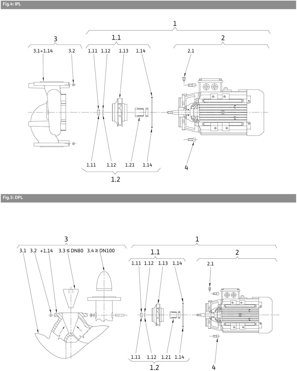
3 Fig.4: IPL Fig.5: DPL
4 D Einbau- und Betriebsanleitung 3 GB Installation and operating instructions 10 F Notice de montage et de mise en service 16 E Instrucciones de instalación y funcionamento 23 I Istruzioni di montaggio, uso e manutenzione 30 GR Οδηγίες εγκατάστασης και λειτουργίας 37 N Montasje- og bruksanvisning 45 H Beépítési és üzemeltetési utasítás 51 PL Instrukcja montażu i obsługi 58 RUS Инструкция по монтажу и эксплуатации 65

5 Deutsch Einbau- 1 und Allgemeines Betriebsanleitung Einbau und Inbetriebnahme nur durch Fachpersonal 1.1 Verwendungszweck Die Trockenläuferpumpen der Baureihen IPL (Inline) und DPL (Doppel) werden als Umwälzpumpen in der Gebäudetechnik eingesetzt in: Warmwasser-Heizungssystemen, Kühl- und Kaltwasserkreisläufen, Industriellen Umwälzsystemen, Wärmeträgerkreisläufen. 1.2 Angaben über die Erzeugnisse Typenschlüssel Beispiel: IPL/-DPL (3-7,5 kw) IPL IPL = Inline-Pumpe DPL DPL= Doppelpumpe 50 Nennweite des Rohranschlusses [mm] /170 Nenndurchmesser des Laufrades [mm] -7,5 Nennleistung des Motors in kw /2 2-poliger Motor Anschluss- und Leistungsdaten Drehzahlen: IPL, DPL 2900, /min Nennweiten DN: IPL DPL Zulässige Temperatur min./max. -10 C bis +120 C Höchstzul. Umgebungstemp. 40 C Max. zulässiger Betriebsdruck 10 bar Isolationsklasse F Schutzart IP 55 Rohr- und Druckmessanschlüsse Flansche PN 16 nach DIN EN mit Druckmessanschlüssen Rp 1 / 8 nach DIN 3858 Zulässige Fördermedien Heizungswasser gem. VDI 2035 Kühl-/Kaltwasser Wasser/Glykol-Gemisch bis 40 % Vol.-Anteil Glykol Wärmeträgeröl Andere Medien auf Anfrage Elektrischer Anschluss 3 ~ 400 V, 50 Hz 3 ~ 230 V, 50 Hz, bis 3 kw einschl. 3 ~ 230 V, 50 Hz, ab 4 kw 3 ~ V 60Hz Kaltleiterfühler Drehzahlumschaltung, Drehzahlregelung Pol-Umschaltung Regelgeräte (Wilo-CR-System) Standardausführung Sonderausführung bzw. Zusatzausrüstung (gegen Mehrpreis) Alternativanwendung der Standardausführung (ohne Mehrpreis) Bei Ersatzteilbestellungen sind sämtliche Daten des Pumpen- und Motortypenschildes anzugeben. Fördermedien: werden Wasser/Glykol-Gemische im Mischungsverhältnis bis 40% Glykolanteil (oder Fördermedien mit anderer Viskosität als reines Wasser) eingesetzt, so sind die Förderdaten der Pumpe entsprechend der höheren Viskosität, abhängig vom prozentualen Mischungsverhältnis und von der Mediumstemperatur zu korrigieren. Zusätzlich ist die Motorleistung bei Bedarf anzupassen. Nur Markenware mit Korrosionsschutzinhibitoren verwenden, Herstellerangaben beachten. Das Fördermedium muss sedimentfrei sein. 2 Sicherheit Diese Betriebsanleitung enthält grundlegende Hinweise, die bei Aufstellung und Betrieb zu beachten sind. Daher ist diese Betriebsanleitung unbedingt vor Montage und Inbetriebnahme vom Monteur sowie dem zuständigen Betreiber zu lesen. Es sind nicht nur die unter diesem Hauptpunkt Sicherheit aufgeführten allgemeinen Sicherheitshinweise zu beachten, sondern auch die unter den folgenden Hauptpunkten eingefügten, speziellen Sicherheitshinweise. 2.1 Kennzeichnung von Hinweisen in der Betriebsanleitung Die in dieser Betriebsanleitung enthaltenen Sicherheitshinweise, die bei Nichtbeachtung Gefährdungen für Personen hervorrufen können, sind mit dem allgemeinen Gefahrensymbol bei Warnung vor elektrischer Spannung mit besonders gekennzeichnet. Einbau- und Betriebsanleitung Wilo-IPL/-DPL (3-7,5 kw) 3

6 Deutsch Bei Sicherheitshinweisen, deren Nichtbeachtung Gefahren für die Pumpe/Anlage und deren Funktion hervorrufen können, ist das Wort eingefügt. ACHTUNG! 2.2 Personalqualifikation Das Personal für die Montage muss die entsprechende Qualifikation für diese Arbeiten aufweisen. 2.3 Gefahren bei Nichtbeachtung der Sicherheitshinweise Die Nichtbeachtung der Sicherheitshinweise kann eine Gefährdung für Personen und Pumpe / Anlage zur Folge haben. Die Nichtbeachtung der Sicherheitshinweise kann zum Verlust jeglicher Schadenersatzansprüche führen. Im einzelnen kann Nichtbeachtung beispielsweise folgende Gefährdungen nach sich ziehen: Versagen wichtiger Funktionen der Pumpe/ Anlage, Gefährdungen von Personen durch elektrische und mechanische Einwirkungen. 2.4 Sicherheitshinweise für den Betreiber Die bestehenden Vorschriften zur Unfallverhütung sind zu beachten. Gefährdungen durch elektrische Energie sind auszuschließen. Vorschriften des VDE und der örtlichen Energieversorgungsunternehmen beachten. 3 Transport und Zwischenlagerung ACHTUNG! Die Pumpe ist bei Transport und Zwischenlagerung gegen Feuchtigkeit und mechanische Beschädigung zu schützen. Der Transport der Pumpe ist mittels zugelassener Lastaufnahmemittel durchzuführen. Sie sind an den Pumpenflanschen und gegebenenfalls am Motor- Außendurchmesser (Sicherung gegen Abrutschen erforderlich!) anzuschlagen. Die Transportösen am Motor dienen dabei nur zur Führung bei Lastaufnahme. Die Transportösen am Motor sind nur zum Transport des Motors, nicht aber der ganzen Pumpe zugelassen. 2.5 Sicherheitshinweise für Inspektions- und Montagearbeiten Der Betreiber hat dafür zu sorgen, dass alle Inspektions- und Montagearbeiten von autorisiertem und qualifiziertem Fachpersonal ausgeführt werden, das sich durch eingehendes Studium der Betriebsanleitung ausreichend informiert hat. Grundsätzlich dürfen Arbeiten an der Pumpe/ Anlage nur im Stillstand durchgeführt werden. 2.6 Eigenmächtiger Umbau und Ersatzteilherstellung Veränderungen der Pumpe/Anlage sind nur nach Absprache mit dem Hersteller zulässig. Originalersatzteile dienen der Sicherheit. Die Verwendung anderer Teile hebt die Haftung für die daraus entstehenden Folgen auf. 2.7 Unzulässige Betriebsweisen Die Betriebssicherheit der gelieferten Pumpe/ Anlage ist nur bei bestimmungsmäßiger Verwendung entsprechend Abschnitt 1 der Betriebsanleitung gewährleistet. Die im Katalog / Datenblatt angegebenen Grenzwerte dürfen auf keinen Fall über- bzw. unterschritten werden. 4 Beschreibung von Erzeugnis und Zubehör 4.1 Beschreibung der Pumpen Alle hier beschriebenen Pumpen sind einstufige Niederdruck-Kreiselpumpen in Kompaktbauweise. Der Motor ist mit einer ungeteilten Welle zur Pumpe hin ausgeführt. Die Pumpen können sowohl als Rohreinbaupumpe direkt in eine ausreichend verankerte Rohrleitung montiert oder auf einen Fundamentsockel gestellt werden. In Verbindung mit einem Regelgerät (Wilo-CR- System) kann die Leistung der Pumpen stufenlos geregelt werden. Dies ermöglicht eine optimale Anpassung der Pumpenleistung an den Bedarf des 4 Wilo AG 10/2005

7 Deutsch Systems und einen wirtschaftlichen Pumpenbetrieb. IPL: Das Pumpengehäuse ist in INLINE-Bauart ausgeführt, d.h. saug- und druckseitige Flansche liegen in einer Mittellinie (Bild 1). Alle Pumpengehäuse sind mit Pumpenfüßen versehen. Die Montage auf einen Fundamentsockel wird ab Motornennleistung 5,5 kw und größer empfohlen. DPL: Zwei Pumpen sind in einem gemeinsamen Gehäuse angeordnet (Doppelpumpe). Das Pumpengehäuse ist in INLINE-Bauart ausgeführt (Bild 2). Alle Pumpengehäuse sind mit Pumpenfüßen versehen. Die Montage auf einen Fundamentsockel wird ab Motornennleistung 4 kw und größer empfohlen. In Verbindung mit einem Regelgerät wird nur die Grundlastpumpe im Regelbetrieb gefahren. Für den Vollastbetrieb steht die zweite Pumpe als Spitzenlastaggregat zur Verfügung. Außerdem kann die zweite Pumpe die Reservefunktion im Störfall übernehmen. 4.2 Lieferumfang IPL: Inline-Pumpe Einbau- und Betriebsanleitung DPL: Doppelpumpe Einbau- und Betriebsanleitung 4.3 Zubehör Zubehör muss gesondert bestellt werden Kaltleiterauslösegerät für Schaltschrankeinbau IPL und DPL: 3 Konsolen mit Befestigungsmaterial für Fundamentaufbau DPL: Blindflansch für Reparatureinsätze 4.4 Geräuscherwartungswerte als Orientierung Schall-Druckpegel pa [db] 1 ) Motorleistung Pumpe mit Motor P N [kw] 1450 min min 1 <0, ) 0, , , , , , , , Räumlicher Mittelwert von Schalldruckpegeln auf einer quaderförmigen Messfläche in 1 m Abstand von der Motoroberfläche. 5 Aufstellung / Einbau 5.1 Montage Einbau erst nach Abschluss aller Schweiß- und Lötarbeiten und der ggf. erforderlichen Spülung des Rohrsystems vornehmen. Schmutz kann die Pumpe funktionsunfähig machen. Die Standardpumpen müssen witterungsgeschützt in einer frost/staubfreien, gut belüfteten und nicht explosiven Umgebung installiert werden. Die Pumpe an gut zugänglicher Stelle montieren, so dass eine spätere Überprüfung oder ein Austausch leicht möglich ist. Senkrecht über der Pumpe ist ein Haken oder eine Öse mit entsprechender Tragfähigkeit (Gesamtgewicht der Pumpe: siehe Katalog / Datenblatt) anzubringen, woran bei Wartung oder Reparatur der Pumpe Hebezeug oder ähnliche Hilfsmittel angeschlagen werden können. Die Pumpe ist mittels zugelassener Lastaufnahmemittel zu heben (siehe Absatz 3). Axialer Mindestabstand zwischen einer Wand und der Lüfterhaube des Motors: Freies Ausbaumaß von min. 200 mm + Ø der Lüfterhaube. Absperreinrichtungen sind grundsätzlich vor und hinter der Pumpe einzubauen, um bei Überprüfung oder Austausch der Pumpe ein Entleeren der gesamten Anlage zu vermeiden. Bei Gefahr durch Rückströmung ist ein Rückflussverhinderer vorzusehen. Rohrleitungen und Pumpe spannungsfrei montieren. Die Rohrleitungen sind so zu befestigen, dass die Pumpe nicht das Gewicht der Rohre trägt. Das Entlüftungsventil (Bild 4, 5, Pos. 2.1) muss immer nach oben zeigen. Bei Einsatz der Pumpe in Klima- oder Kälteanlagen kann das in der Laterne anfallende Kondensat gezielt über vorhandene Bohrungen abgeführt werden. Jede Einbaulage außer "Motor nach unten" ist zulässig. Die Einbaulage mit waagerechter Motorwelle ist bei den Baureihen IPL und DPL bis zu einer Motorleistung von 7,5 kw zulässig. Einbaulagen: IPL siehe Bild 1 DPL siehe Bild 2 Der Motorklemmenkasten darf nicht nach unten zeigen. Im Bedarfsfall kann der Motor bzw. Einstecksatz nach Lösen der Sechskantschrauben gedreht werden. ACHTUNG! ACHTUNG! Beim Verdrehen die Gehäuse-O-Ring- Dichtung nicht beschädigen. Beim Fördern aus einem Behälter ist für ein stets ausreichendes Flüssigkeitsniveau über dem Saugstutzen der Pumpe zu sorgen, damit die Pumpe keinesfalls trocken läuft. Der Mindest-Zulaufdruck muss eingehalten werden. Einbau- und Betriebsanleitung Wilo-IPL/-DPL (3-7,5 kw) 5

8 Deutsch ACHTUNG! 5.2 Elektrischer Anschluss Der elektrische Anschluss ist von einem beim örtlichen EVU zugelassenen Elektroinstallateur und entsprechend den geltenden VDE-Vorschriften auszuführen. Der elektrische Anschluss muss nach VDE 0730/ Teil 1 über eine feste Anschlussleitung erfolgen, die mit einer Steckvorrichtung oder einem allpoligen Schalter mit mindestens 3 mm Kontaktöffnungsweite versehen ist. Um den Tropfwasserschutz und die Zugentlastung der Kabelverschraubung sicherzustellen, ist eine Anschlussleitung mit ausreichendem Außendurchmesser zu verwenden. Es ist durch entsprechende Positionierung der Kabelverschraubung oder durch entsprechende Kabelverlegung sicherzustellen, dass kein Tropfwasser in den Klemmenkasten laufen kann. Bei Einsatz der Pumpen in Anlagen mit Wassertemperaturen über 90 C muss eine entsprechend wärmebeständige Anschlussssleitung verwendet werden. Die Anschlussleitung ist so zu verlegen, dass in keinem Fall die Rohrleitung und/oder das Pumpen- und Motorgehäuse berührt werden. Stromart und Spannung des Netzanschlusses überprüfen. Typenschilddaten des Motors beachten. Netzseitige Absicherung: abhängig vom Motornennstrom. Pumpe / Anlage vorschriftsmäßig erden. Das Anschlussschema für den Elektroanschluss befindet sich im Klemmenkastendeckel (s. auch Bild 3). Der Motor muss gegen Überlast durch einen Motorschutzschalter oder durch das Kaltleiterauslösegerät abgesichert werden. Einstellung des Motorschutzschalters: Direktanlauf: Einstellung auf Motornennstrom nach Angaben des Motortypenschildes, Y--Anlauf: Ist der Motorschutzschalter in die Zuleitung zur Y--Schützkombination geschaltet, so erfolgt die Einstellung wie bei Direktanlauf. Ist der Motorschutzschalter in einen Strang der Motorzuleitung (U1/V1/W1 oder U2/ V2/W2) geschaltet, so ist der Motorschutzschalter auf den Wert 0,58 Motornennstrom einzustellen. In Sonderausführung ist der Motor mit Kaltleiterfühlern ausgestattet. Kaltleiterfühler am Kaltleiterauslösegerät anschließen. ACHTUNG! Bei Anlagen, die isoliert werden, darf nur das Pumpengehäuse einisoliert werden, nicht Laterne und Motor. An die Klemmen Kaltleiterfühler darf nur eine max. Spannung von 7,5V angelegt werden, höhere Spannung zerstört die Kaltleiterfühler. Bild 3 Einschaltart Direkt Y-- Anlauf Der Netzanschluss an das Klemmenbrett ist abhängig von der Motorleistung P 2, von der Netzspannung und von der Einschaltart. Die erforderliche Schaltung der Verbindungsbrücken im Klemmenkasten ist folgender Tabelle und Bild 3 zu entnehmen.. Motorleistung P 2 3 kw Netzspannung Motorleistung P 2 4 kw 3 ~ 230 V 3 ~ 400 V 3 ~ 400 V Bei Anschluss von automatisch arbeitenden Schaltgeräten die entsprechende Einbau- und Betriebsanleitung beachten. 6 Inbetriebnahme Pumpe, Saug- und Zulaufleitung müssen gefüllt und entlüftet sein. ACHTUNG! -Schaltung (3a) Verbindungsbrücken entfernen (3c) Y-Schaltung (3b) nicht möglich Netzspannung -Schaltung (3a) Verbindungsbrücken entfernen (3c) Die Pumpe darf nicht trocken laufen. Trockenlauf zerstört die Gleitringdichtung! Um Kavitationsgeräusche und -schäden zu vermeiden, muss ein Mindest-Zulaufdruck am Saugstutzen der Pumpe gewährleistet werden. Dieser Mindest-Zulaufdruck ist abhängig von der Betriebssituation und dem Betriebspunkt der Pumpe und muss dementsprechend festgelegt werden. Wesentliche Parameter zur Festlegung des Mindest-Zulaufdruckes sind der NPSH-Wert der Pumpe in ihrem Betriebspunkt und der Dampfdruck des Fördermediums. Pumpen durch Lösen der Entlüftungsschrauben (Bild 4, 5, Pos. 2.1) entlüften Verbrühungsgefahr! Je nach Temperatur des Fördermediums und Systemdruck kann beim vollständigen Öffnen der Entlüftungsschraube heißes Fördermedium in flüssigem oder dampfförmigem Zustand austreten bzw. unter hohem Druck herausschießen. Durch kurzzeitiges Einschalten überprüfen, ob die Drehrichtung mit dem Pfeil auf dem Motor (Lüfterhaube bzw. Flansch) übereinstimmt. Bei falscher Drehrichtung ist wie folgt zu verfahren: Bei direktem Anlauf: 2 Phasen am Klemmenbrett des Motors vertauschen (z.b. L1 gegen L2), 6 Wilo AG 10/2005

9 Deutsch Bei Y--Anlauf: Am Klemmenbrett des Motors von 2 Wicklungen jeweils Wicklungsanfang und Wicklungsende vertauschen (z.b. V1 gegen V2 und W1 gegen W2). Die Fördermenge soll 10% der maximalen Förderleistung nicht unterschreiten. Prüfen, ob die Stromaufnahme nicht den Nennstrom auf dem Typenschild übersteigt. ACHTUNG! Die Pumpe darf nicht länger als 10 Minuten bei Fördermenge Q=0 m³/h (geschlossenes Absperrventil) betrieben werden. Verbrennungs-/Erfrierungsgefahr bei Berührung der Pumpe! Je nach Betriebszustand der Pumpe bzw. der Anlage (Temperatur des Fördermediums) kann die gesamte Pumpe sehr heiß oder sehr kalt werden. Während des Betriebes Abstand halten! 7 Wartung Vor Wartung- oder Instandsetzungsarbeiten Anlage spannungsfrei schalten und gegen unbefugtes Wiedereinschalten sichern. Verbrühungsgefahr! Bei hohen Wassertemperaturen und Systemdrücken Pumpe vorher abkühlen lassen. 7.1 Gleitringdichtung Während der Einlaufzeit können geringfügige Tropfleckagen auftreten. Es ist jedoch wöchentlich eine Sichtkontrolle erforderlich. Bei deutlich erkennbarer Leckage ist ein Dichtungswechsel vorzunehmen. Wilo bietet ein Reparatur- Set an, das die für einen Wechsel notwendigen Teile enthält. Wechsel der Gleitringdichtung (Bild 4, 5) : Anlage spannungsfrei schalten und gegen unbefugtes Wiedereinschalten sichern. Absperrarmaturen vor und hinter der Pumpe schließen. Pumpe durch Öffnen der Entlüftungsschraube (Pos. 2.1) drucklos machen. Verbrühungsgefahr! Bei heißen Fördermedien Motor abklemmen, falls Kabel für die Demontage des Motors zu kurz ist. Motorbefestigungsschrauben (Pos. 4) am Motorflansch lösen und Motor mit Laufrad und Wellendichtung mit geeignetem Hebezeug von der Pumpe abheben. Laufradbefestigungsmutter (Pos. 1.11) lösen, darunterliegende Unterlegscheibe (Pos. 1.12) abnehmen und Laufrad (Pos. 1.13) von Pumpenwelle abziehen. Gleitringdichtung (Pos. 1.21) von der Welle abziehen. Pass-/Sitzflächen der Welle sorgfältig säubern. Gegenring der Gleitringdichtung mit Dichtmanschette aus dem Laternenflansch sowie den O- Ring (Pos. 1.14) entfernen und die Dichtungssitze säubern. Neuen Gegenring der Gleitringdichtung mit Dichtmanschette in den Dichtungssitz des Laternenflansches eindrücken. Als Schmiermittel kann handelsübliches Geschirrspülmittel verwendet werden. Neuen O-Ring in die Nut des O-Ringsitzes der Laterne montieren. Neue Gleitringdichtung bis Ende Kegelsitz auf die Welle ziehen. Als Schmiermittel kann handelsübliches Geschirrspülmittel verwendet werden. Laufrad mit Unterlegscheibe und Mutter montieren, dabei am Laufradaußendurchmesser kontern. Beschädigungen der Gleitringdichtung durch Verkanten vermeiden. ACHTUNG! Motor mit Laufrad und Wellendichtung mit geeignetem Hebezeug vorsichtig in das Pumpengehäuse einführen und verschrauben. Motorkabel anklemmen. ACHTUNG! Vorgeschriebenes Schraubenanzugsmoment beachten (siehe 7.3) Vorgeschriebenes Schraubenanzugsmoment beachten (siehe 7.3) 7.2 Motor Erhöhte Lagergeräusche und ungewöhnliche Vibrationen zeigen einen Lagerverschleiß an. Das Lager bzw. der Motor muss dann gewechselt werden. Wechsel des Motors (Bild 4, 5): Anlage spannungsfrei schalten und gegen unbefugtes Wiedereinschalten sichern. Absperrarmaturen vor und hinter der Pumpe schließen. Pumpe durch Öffnen der Entlüftungsschraube (Pos. 2.1) drucklos machen. Verbrühungsgefahr! Bei heißen Fördermedien Motoranschlussleitungen entfernen. Motorbefestigungsschrauben (Pos. 4) am Motorflansch lösen und Motor mit Laufrad und Wellendichtung mit geeignetem Hebezeug von der Pumpe abheben. Neuen Motor mit Laufrad und Wellendichtung mit geeignetem Hebezeug vorsichtig in das Pumpengehäuse einführen und verschrauben. ACHTUNG! Vorgeschriebenes Schraubenanzugsmoment beachten (siehe 7.3) Motorkabel anklemmen. Einbau- und Betriebsanleitung Wilo-IPL/-DPL (3-7,5 kw) 7
 kann die gesamte Pumpe sehr heiß oder sehr kalt werden. Während des Betriebes Abstand halten!")
10 Deutsch 7.3 Schraubenanzugsmomente Schraubenverbindung Anzugsdrehmoment Nm ± 10% Montageanweisungen Laufrad - Welle Pumpengehäuse - Motorflansch M 10 M M gleichmäßig über Kreuz anziehen 8 Störungen, Ursachen und Beseitigung Störungen Ursachen Beseitigung Pumpe läuft nicht an oder setzt aus Pumpe blockiert Motor spannungsfrei schalten, Ursache der Blockierung entfernen; falls Motor blockiert, Motor / Stecksatz überholen / tauschen Kabelklemme lose alle Klemmenschrauben anziehen Sicherungen defekt Sicherungen prüfen, defekte Sicherungen auswechseln Motor schadhaft Kundendienst einschalten Motorschutzschalter hat ausgelöst Pumpe druckseitig auf Nennvolumenstrom eindrosseln Motorschutzschalter falsch eingestellt Motorschutzschalter auf den richtigen Nennstrom des Typenschildes einstellen. Motorschutzschalter durch zu hohe Umgebungstemperatur beeinflusst Motorschutzschalter versetzen oder durch Wärmeisolierung schützen Kaltleiterauslösegerät hat ausgelöst Motor und Lüfterhaube auf Verunreinigungen prüfen und ggfs. säubern, Umgebungstemperatur prüfen und ggfs. durch Zwangsbelüftung Umgebungstemperatur 40 C sicherstellen Pumpe läuft mit Falsche Drehrichtung Drehrichtung prüfen, evtl. ändern verringerter Leistung Druckseitiges Absperrventil gedrosselt Absperrventil langsam öffnen Drehzahl zu gering falsche Klemmenbrückung (Y anstatt ) beheben Luft in Saugleitung Undichtheiten an Flanschen beheben, entlüften Pumpe macht Geräusche Unzureichender Vordruck Vordruck erhöhen, Mindestdruck am Saugstutzen beachten, saugseitigen Schieber und Filter überprüfen und ggfs. reinigen Motor hat Lagerschaden Pumpe durch WILO-Kundendienst oder Fachbetrieb überprüfen und ggfs. instandsetzen lassen Laufrad schleift an Planflächen und Zentrierungen sowie zwischen Laterne und Pumpengehäuse überprüfen und ggfs. säubern. Lässt sich die Betriebsstörung nicht beheben, wenden Sie sich bitte an Ihren Sanitär- und Heizungsfachhandwerker oder an den WILO-Kundendienst. 8 Wilo AG 10/2005

11 Deutsch 9 Ersatzteile Lieferbare Ersatzteile (siehe Bild 4, 5): 1 Austauschsatz komplett 1.1 Bausatz Laufrad mit 1.11 Mutter 1.12 Unterlegscheibe 1.13 Laufrad 1.14 O-Ring 1.2 Bausatz Gleitringdichtung mit 1.11 Mutter 1.12 Unterlegscheibe 1.14 O-Ring 1.21 Gleitringdichtung kpl. 2 Austauschsatz Motor 2.1 Entlüftungsschraube 3 Pumpengehäuse komplett mit 1.14 O-Ring 3.1 Pumpengehäuse (IPL. DPL) 3.2 Stopfen für Druckmessanschlüsse ACHTUNG! 3.3 Umschaltklappe DN 80 (nur DPL-Pumpen) 3.4 Umschaltklappe DN 100 (nur DPL-Pumpen) 4 Befestigungsschrauben für Motorflansch / Pumpengehäuse (Auch im Austausch-Satz Motor) Eine einwandfreie Funktion der Pumpe kann nur gewährleistet werden, wenn Wilo-Originalersatzteile verwendet werden. Bei Ersatzteilbestellungen bitte o.g. Ersatzteilnummern und -bezeichnungen sowie sämtliche Daten des Pumpen- und Motortypenschildes angeben. Technische Änderungen vorbehalten! Einbau- und Betriebsanleitung Wilo-IPL/-DPL (3-7,5 kw) 9
 4 Befestigungsschrauben für Motorflansch / Pumpengehäuse (Auch im Austausch-Satz Motor) Eine einwandfreie Funktion der Pumpe kann nur gewährleistet werden,")
12 English 1 General Installation and service by qualified personnel only. 1.1 Fields of applications Series IPL (Inline) and DPL (Dual) glanded pumps are used for circulating duties in mechanical building services to serve: Central hot water heating systems Chilled and condenser water systems Closed industrial circulating systems Heat transfer systems. 1.2 Product information Serial codes IPL/-DPL (3-7,5 kw) IPL IPL = Inline-pump DPL DPL= Double-pump 50 Pump connection size [mm] /170 Nominal impeller diameter [mm] -7,5 Rated motor power kw /2 2-pole motor Technical data Motor speeds: IPL, DPL 2900, /min Connection sizes DN: IPL DPL Permissible temperature min./max. 10 C to +120 C Maximum ambient temperature 40 C Maximum working pressure 10 bar Insulation class F Enclosure rating IP 55 Pipe and gauge connections Flanges PN 16 to DIN EN with gauge tappings 1 / 8 BSP Permissible fluids Heating water to VDI 2035 Chilled/condenser water Water/Glycol-mixtures up to 40 % glycol content Heat transfer oil Other media on request Electrical wiring connections 3 ~ 400 V, 50 Hz 3 ~ 230 V, 50 Hz: up to 3 kw 3 ~ 230 V, 50 Hz:4 kw and above 3 ~ V 60Hz Thermal resistor sensor Variable speed control Pol change multi-speed motors Automatic control gear (Wilo-CR-System) Standard design Special design or additional equipment at extra cost Alternative application of standard design (no additional costs) When ordering spare parts, all data of pump and motor name plate must be stated. Permissible fluids: When using water/glycol mixtures of a mixing ratio up to 40% glycol (or fluids of viscosities other than water) it will be necessary to correct the hydraulic pump data according to the higher viscosity, depending on the mixing ratio and the fluid temperature. Only approved makes of additives with corrosion inhibitors in strict compliance with manufacturers` instructions must be used. The fluid must be free of sediments. 2 Safety rules These instructions contain basic rules on safety aspects which must be strictly adhered to for installation and operation. It is therefore imperative for Installers and Operators to study these instructions prior to installation and commissioning. Not only the safety references under this main heading need attention but also those added and specifically marked under the ensuing headers. 2.1 Symbols marking safety reference in these instructions Safety precautions in these operating instructions which, if not followed, could cause personal injury are indicated by the symbol: Safety precautions warning of danger due to electricity are indicated by the symbol: The following symbol is used to indicate that by ignoring the relevant safety instructions, damage could be caused to the pump/machinery and its functions: ATTENTION! 10 Wilo AG 10/2005

13 English 2.2 Trade qualifications The personnel installing the pump must have the appropriate qualification for this work. 2.3 Dangers from non-observance of safety rules Non-observance of safety reference may cause harm to persons and pump or installation. Failure to comply with safety reference could invalidate all warrantly/damage claims. In detail, non-compliance may e.g. cause the following danger situations: Failure of important pump or machinery functions Injury resulting from electrical or mechanical factors 2.4 Safety reference for the operator Ruling local regulations on the prevention of accidents must be observed. Danger from electrical energy must be excluded (conforming to local and general regulations). The lifting eyebolts of the motor are suitable for the weight of the motor. It s not allowed to carry the complete pump on the lifting eyebolts of the motor. 2.5 Safety reference for inspections and installation It is the operators responsibility to ensure that all inspection and installation work is carried out by authorized and qualified personnel only, after having made themselves fully conversant with these instructions. On principle, work must be carried out only with the pump/plant switched off and at complete standstill. 2.6 Arbitary alterations and spare parts procurement Any alterations to the pump/plant are only permitted if authorized by the manufacturers. Original spare parts ensure safety and reliability. The use of unauthorized parts could invalidate any claims for consequential damages. 2.7 Inadmissible operating conditions Operational safety of the plant is only ensured if used in strict accordance with chapter 1 of these instructions. Limits stated in catalogue/data sheet must not be exceeded under any circumstances. 3 Transport and intermediate storage ATTENTION! The pump must be protected from moisture and mechanical damage at all times during transport and intermediate storage. It must be carefully handled by means of authorized lifting gear. The lifting gear has to be fitted on the pumpflanges and perhaps on the outer diameter of the motor (Attention: the lifting gear has to be fixed against slide slip!). The lifting eyebolts on the motor are only suitable for fixing the position of the lifting gear. 4 Description of product and accessories 4.1 Description of the pumps All pumps dealt with herein are single-stage, lowpressure centrifugal pumps in monoblock design, with extended single motor/pump shaft. The pumps can be installed either pipe-supported in sufficiently anchored pipework or base-mounted on a plinth. Its capacity can be infinitely varied if used in conjunction with the respective control gear (Wilo- CR-System). This will enable an optimum adaptation of pump performance to actual load demands and an economical pump operation. IPL: The pump housing is of the inline design with suction and discharge connection axially in line (Fig.1). All pump housings are designed with the possibility of base mounting on a plinth. Pumps with a power 5,5kW and above to be based mounted. DPL: Two pumps heads mounted in a common housing (double-pump), the pump housing is being of inline design (Fig.2). All pump housings are designed with the possibility of base mounting on a plinth. Pumps with a power 4 kw and above to be based mounted. Installation and operating instructions Wilo-IPL/-DPL (3-7,5 kw) 11

14 English When used in conjunction with an automatic variable speed controller only the base-duty pump is operated variably. The second pump remains available for parallel operation to cover peak-load demand and additionally, for standby duty to take over under fault conditions. 4.2 Scope of supply IPL: Single pump Installation and operating instructions. DPL: Double pump Installation and operating instructions. 4.3 Accessories Accessories must be ordered separately. PTC trip relay for switchboard mounting. IPL and DPL: 3 support feet and sundries for base mounting. DPL: Blind flange for repair purpose 4.4 Expected noise values as guideline Sound pressure level pa [db] 1 ) power of motor 5 Siting / Installation Pump with Motor P N [kw] 1450 min min 1 <0, , , , , , , , , ) Average area sound pressure level value measured in a cubic area at a distance of 1 m to the motor surface. 5.1 Installation Installation only after all welding/soldering on the pipework is completed and the pipe system has been flushed out. Foreign matter and impurities may cause damage to the pump. Standard design pumps must be installed in a frost- and dustfree, well-ventilated and non potential explosive environment. Mount the pump in an easily accessible position in order to facilitate later inspections or exchange. Provide and place a hook or eyebolt of respective load bearing capacity (total weight of pump: see catalogue/data sheet) vertically above the pump, suitable for taking lifting gear or other mechanical aids capable of handling the pump for maintenance or repairs. The pump must be carefully handled by means of authorized lifting gear (see chap. 3). Minimum axial clearance between a wall and the motor fan cover: clearance required for removal to min. 200 mm + Ø of fan cover. Isolating valves must be provided and installed on suction and discharge ports in order to avoid draining the whole pipe system when servicing or exchanging the pump. At the risk of backflow a non-return valve must be provided. Pump must be mounted free of stress from the pipework. The pipes must be attached in such way that the pump does not bear the weight of the pipes. The venting valve always must face upwards (Fig. 4, 5, pos. 2.1). When pumps are used in airconditioning/cooling systems, it is possible to drain off the condensation of the lantern through drilled holes. Any mounting position except motor downwards is allowed. The mounting position with horizontal motor shaft of the IPL and DPL range is permissible for pumps with 7,5 kw motor power. Mounting positions: IPL see Fig. 1 DPL see Fig. 2 The motor terminal box must not face downwards. If necessary, the motor or the motor impeller unit can be turned after removing the screws. ATTENTION! ATTENTION! ATTENTION! When turning, take care not to damage the housing o-ring. When sucking from tank make sure that the level of liquid is always above the pump suction port to avoid dry-running of the pump.the minimum inlet pressure must be maintained. For units which are be insulated, only the pump housing may be insulated, not the lantern and the motor. 5.2 Electrical wiring All electrical wiring to be carried out by qualified and licensed electricians in strict conformity to ruling local regulations. All wiring and external gear must comply with ruling regulations (use of cables, all-pole switches, air gaps, etc. in accordance with the latest edition of IEE wiring regulations). For protection against drip water and to ensure a firm gland grip the mains supply cable must be of sufficiently large size. The position of the cableentrance in electrical connection box of the motor or the cableposition has to protect the electrical connection box against drip water. 12 Wilo AG 10/2005

15 English Heat-resistant power cable must be used for pumps in systems with water temperatures above 90 C. The power cable must be routed in such a way to avoid any contact with pipework and/or pump/ motor housings. Check available mains power supply and voltage. Observe motor name plate data. Mains power supply fuses: depending on motor full-load current. The pump/installation must be earthed in compliance with the applicable regulations. The power wiring diagramm is inside the terminal box cover (see also Fig. 3). ATTENTION! Figure 3 Starting arrangement Mains power supply to the terminal depends on rated motor power P 2, the supply voltage and the starting method. For the required terminal bridge connections refer to table below and Fig. 3. Comply with respective installation and operating instructions when wiring to automatic pump control gear. 6 Commissioning Pump, suction and inlet piping must be filled and properly vented. ATTENTION! Terminals must not be connected to a voltage over 7.5V, a higher voltage will damage the PTC-sensors. Motor power rating P 2 3 kw Mains power Motor power rating P 2 4 kw Mains power 3 ~ 230 V 3 ~ 400 V 3 ~ 400 V DOL-Starting Y-- Starting -connections (3a) Remove terminal bridges (3c) Y-connections (3b) Not possible -connections (3a) Remove terminal bridges (3c) The pump must not run dry. Dry-running will damage the mechanical seal! In order to avoid noise and damage due to cavitation a minimum inlet pressure must be ensured at the pump suction port. This minimum inlet pressure depends on the operating conditions and the duty point of the pump and must be accordingly calculated. Significant criteria for calculating the minimum required inlet pressure are the NPSHlevel of the pump at its operating point and the vapour pressure of the liquid. Vent pumps by unscrewing its air vent plugs (Fig. 4, 5, pos. 2.1). Beware of scalding! Depending on the fluid temperature and the system pressure, if the vent screw is completely loosened hot liquid or gas can escape or even shoot out at higth pressure. Check the direction of rotation by briefly switching on the pump and make sure that rotation coresponds with the arrow on the motor (fan cover or flange). If necessary, correct as follows: DOL-Starting: Change any 2 phase wires at the motor terminals (e.g. L1 and L2). Y--Starting: At the motor terminals change winding start and end terminal connections respectively of 2 windings (e.g. V1 with V2 and W1 with W2). Ensure a minimum flow of about or higher than 10 % of the maximum flow of the pump. Check that the current input does not exceed the valve indicated on the motor data plate. ATTENTION! The pump must not run for longer than 10 minutes with a flow rate of Q = 0 m³/h (closes discharge valve). Risk of burning / frostbitten if the pump is touched! Depending on the operating conditions of the pump or installation (fluid temperature), the entire pump can become very hot or very cold. Keep distance during pump operation! 7 Maintenance Before starting service or repair work switch off the plant and secure against unauthorized switching. Beware of scalding! In the event of high temperatures and high system pressure, the pumps should be allowed to cool down. 7.1 Mechanical seal Slight may occur during the running-in period. Visual leakage checks are however required weekly. Distinctly visible leakage will require an exchange of the seal. WILO offers a repair set containing all parts required for an exchange. Exchange of the mechanical seal (Fig. 4, 5): Switch off power supply and secure against unauthorized switching. Close isolating valves at both pump ports. Lower the pressure of the pump by opening the air vent plugs (pos. 2.1). Beware of scalding! In the event of hot liquids, Disconnect wires from motor terminals if cable length is too short for dismantling the motor. Unscrew the motor fixing-screws (pos. 4) at motorflange and lift the motor with impeller and Installation and operating instructions Wilo-IPL/-DPL (3-7,5 kw) 13
. ATTENTION!")
16 English shaft seal off pumphousing by means of suitable lifting gear. Unscrew the impeller fixing-nut (pos. 1.11) together with the plain washer (pos. 1.12) and pull off the impeller (pos. 1.13) from the pumpshaft. Remove mechanical seal (pos. 1.21) from shaft. Carefully clean fitting/seat area of shaft. Remove the stationary ring of the mechanical seal with seal collar from its seat in the lantern flange, remove the o-ring (pos. 1.14) and clean the seat areas. Press the new stationary ring of the mechanical seal with seal collar on its seat in the lantern flange. Use ordinary liquid soap for lubrication. Insert new o-ring into the groove on its seat of the lantern. Push new mechanical seal up to the end of the conical seat right onto shaft. Use ordinary liquid soap for lubrication. Refit impeller with plain washer and nut, fix by the outer impellerdiameter. Handle carefully to save the mechanical seal. ATTENTION! Observe screw tightening torque regulations (see 7.3). Exchange of the motor (Fig. 4, 5): Switch off power supply and secure against unauthorized switching. Close isolating valves at both pump ports. Lower the pressure of the pump by opening the air vent plug (pos. 2.1). Beware of scalding! In the event of hot liquids. Disconnect wires from motor terminals Unscrew the motor fixing-screws (pos. 4) at motorflange and lift the motor with impeller and shaft seal off pumphousing by means of suitable lifting gear. ATTENTION! Rewire power leads to motor terminals. 7.3 Screw tightening torque Screw Connection Observe screw tightening torque regulations (see 7.3). Tightening Torque Nm ± 10% Mounting Instructions ATTENTION! Remount the motor with impeller and shaft seal by means of suitable lifting gear and secure the motorflange connection with bolts. Observe screw tightening torque regulations (see 7.3). Rewire power leads to motor terminals. 7.2 Motor Increasing bearing noise and undue vibrations indicate a worn bearing. The bearing or the complete motor then needs replacing. Impeller - Shaft Pump Housing - Motorflange M 10 M M tighten the screws equally crosswise 14 Wilo AG 10/2005

17 English 8 Faults, causes and remedies Faults Possible cause Remedy Pump does not start or fails to run Pump chocked up switch off power supply, take-off pump head, remove obstruction; if motor blocked, overhaul/exchange motor/pump head Loose terminals tighten all terminals Defect fuses check fuses, change defect fuses Faulty motor call service Tripped overload relay throttle hydraulic flow rate down to nominal at discharge side of pump Incorrectly set trip relay reset thermal overloads to name plate FLC-value Thermal overload are influenced by excessive ambient temperature reposition overload relay or protect by thermal insulation Tripped PTC-relay check motor and fan cover for dirt/dust accumulation and clean if necessary; check ambient temperature and if necessary, ensure an ambient temperature 40 C by forced ventilation. Pump runs at reduced incorrect rotation check direction of rotation, if necessary capacity Discharge valve throttled too far slowly open isolating valve Speed too low correct wrong terminal bridging (Y in lieu ) Air in suction pipe check and correct flange leakages, eventually vent pipe section Pump makes noise insufficient inlet pressure raise inlet pressure, ensure minimum required inlet pressure at suction port, check and if necessary clean suctionside isolating valve and strainer Faulty motor bearings Arrange for pump to be inspected and, if necessary, to be repaired by Wilo or other authorized service. Impeller scratches Test the contact between lantern and pumphousing. Clean it, if necessary. If the fault cannot be remedied, please contact your local plumbing and heating specialist or WILO customer services. 9 Spare parts Available spare parts (see Fig. 4, 5): 1 Exchange set complete 1.1 Set impeller with 1.11 Nut 1.12 Plain washer 1.13 Impeller 1.14 O-ring 1.2 Set mechanical seal with 1.11 Nut 1.12 Plain washer 1.14 O-ring 1.21 Mechanical seal complete 2 Exchange set motor 2.1 Vent screw 3 Pumphousing complete with 1.14 O-ring ATTENTION! 3.1 Pumphousing (IPL, DPL) 3.2 Plug for gauge tappings 3.3 Check flap DN 80 (DPL-Pumps only) 3.4 Check flap DN 100 (DPL-Pumps only) 4 Fixing-screws motorflange / pumphousing (also within exchange set motor) Only original Wilo spare parts are to be used to ensure the fault-free operation of the pump. When ordering spare parts, please state spare part numbers - descriptions and all data of pump and motor name plate. Technical modifications reserved! Installation and operating instructions Wilo-IPL/-DPL (3-7,5 kw) 15

18 Français 1 Généralités L installation et la mise en service devront être réalisées uniquement par du personnel qualifié. 1.1 Applications Les pompes à rotor sec des séries IPL (in-line) et DPL (double) sont utilisées comme pompes de circulation en technique de construction pour: les dispositifs de chauffage à l'eau chaude, de climatisation, Les systèmes de circulation industriels, les circuits caloporteurs. 1.2 Caractéristiques du produit Plaque signalétique IPL/-DPL (3-7,5 kw) IPL IPL = Pompe in-line DPL DPL= Pompe double 50 Diamètre nominal de la bride de raccordement [mm] /170 Diamètre nominal de la roue [mm] -7,5 Puissance nominale du moteur en kw /2 Moteur à 2 pôles Raccordement et puissance Vitesse de rotation: IPL, DPL 2900, 1450 tr/mn Diamètres nominaux DN:IPL DPL Température min./max. admise de -10 C à +120 C Temp. ambiante maxi. admissible 40 C Pression maxi admissible 10 bars Classe d isolation F Type de protection IP 55 Brides de raccordement et prises de pression avec prises de pression Rp 1 / 8 selon la norme DIN 3858 Bride PN 16 selon la norme DIN Fluides véhiculés autorisés Eau de chauffage selon VDI 2035 Eau de refroidissement/eau froide Mélange eau/glycol (maximum 40 % de glycol) Huile caloporteuse Autres fluides sur demande Raccordement électrique 3 ~ 400 V, 50 Hz 3 ~ 230 V, 50 Hz, jusque 3 kw inclus 3 ~ 230 V, 50 Hz, à partir de 4 kw 3 ~ V 60Hz Capteurs thermistor Changement de vitesse, variation de vitesse Changement du nombre des pôles Coffret de variation de vitesse (WILO-CR-System) Modèle standard Modèle spécial selon l'équipement (moyennant un supplément de prix) Emploi alternatif du modèle standard (sans frais supplémentaires) Lors de toute commande de pièces détachées, il convient de mentionner toutes les données de la plaque signalétique des pompes et du moteur. Fluides véhiculés: Si l'on utilise un mélange eau/glycol où la proportion de glycol (ou de fluides véhiculés ne présentant pas la même viscosité que l'eau pure) ne dépasse pas 40%, il convient de rectifier les caractéristiques de la pompe pour les adapter à la viscosité plus élevée, en fonction des proportions exprimées en pourcentage et de la température ambiante. En outre, on peut adapter, si nécessaire, la capacité du moteur. N utiliser que des produits de marques dotés d inhibiteurs de protection contre la corrosion, respecter les consignes du fabricant. Le fluide véhiculé ne doit comporter aucun résidu. 2 Sécurité La présente notice contient des instructions primordiales, qui doivent être respectées lors du montage et de la mise en service. C'est pourquoi elle devra être lue attentivement par le monteur et l'utilisateur et ce, impérativement avant le montage et la mise en service. Il y a lieu d'observer non seulement les instructions générales de cette section, mais aussi les prescriptions spécifiques abordées dans les points suivants. 2.1 Signalisation des consignes de la notice Les consignes de sécurité contenues dans cette notice qui, en cas de non-observation, peuvent 16 Wilo AG 10/2005

19 Français représenter un danger pour les personnes, sont symbolisées par le logo suivant: En cas de danger électrique, le symbole indiqué est le suivant: Les consignes de sécurité dont la non-observation peut représenter un danger pour l installation et son fonctionnement sont indiquées par le signe: ATTENTION! 2.2 Qualification du personnel Il convient de veiller à la qualification du personnel amené à réaliser le montage. 2.3 Dangers encourus en cas de non-observation des consignes La non-observation des consignes de sécurité peut constituer un danger pour les personnes, la pompe ou l installation. Elle peut également entraîner la suspension de tout recours en garantie. Plus précisément, les dangers encourus peuvent être les suivants: Défaillance de fonctions importantes de la pompe ou de l'installation. Danger pour les personnes en cas de dysfonctionnement électrique et mécanique de la machine. 2.4 Consignes de sécurité pour l'utilisateur Il convient d observer les consignes en vue d exclure tout risque d accident. Il y a également lieu d exclure tous dangers liés à l énergie électrique. Respecter les consignes de la VDE (Union des électrotechniciens allemands) et de votre distributeur d électricité local. 3 Transport et stockage avant utilisation ATTENTION! Pendant le transport et le stockage avant utilisation, protéger la pompe contre l'humidité et tout dommage mécanique. Le transport de la pompe doit être effectué au moyen d'un dispositif de suspension autorisé. Il doit être fixé aux brides des pompes et, s il y a lieu, au diamètre extérieur du moteur (garantie contre glissements indispensable!). Les œillets de suspension du moteur ne servent qu à la conduite en cas de levage. Les œillets de suspension du moteur ne sont autorisés que pour le transport du moteur, mais pas pour la pompe entière. 2.5 Conseils de sécurité pour les travaux d'inspection et de montage L'utilisateur doit faire réaliser ces travaux par une personne spécialisée qualifiée ayant pris connaissance du contenu de la notice. Les travaux réalisés sur la pompe ou l installation ne doivent avoir lieu que si les appareillages correspondants sont à l arrêt. 2.6 Modification du matériel et utilisation de pièces détachées non agréées Toute modification de la pompe ou de l'installation ne peut être effectuée que moyennant l'autorisation préalable du fabricant. Les pièces de rechange originales garantissent la sécurité. L utilisation d autres pièces peut dégager notre société de toute responsabilité. 2.7 Modes d'utilisation non autorisés La fiabilité du matériel livré n est garantie que si les prescriptions précisées au chap. 1 de la notice d utilisation sont respectées. Les limites mentionnées dans le catalogue/la fiche technique ne peuvent en aucun cas être dépassées ou ne pas être atteintes. 4 Description du produit et de ses accessoires 4.1 Description de la pompe Toutes les pompes décrites ci-dessous sont des pompes centrifuges basse pression à un étage compactes et moteur avec arbre long. Les pompes peuvent être directement installées en ligne dans un système de tuyauterie suffisamment ancré ou être montées sur un socle de fondation. Un coffret de variation de vitesse (WILO-CR-System) permet de régler la puissance des pompes en continu. Ce système permet une adaptation optimale de la puissance de la pompe aux besoins du Notice de montage et de mise en service Wilo-IPL/-DPL (3-7,5 kw) 17

20 Français système, ainsi qu un mode de fonctionnement économique. IPL: Le corps de pompe est réalisé selon le type IN- LINE, c est-à-dire que les brides côté aspiration et côté refoulement se situent sur une même ligne médiane (Figure 1). Tous les corps de pompe sont munis de pieds. Le montage sur un socle est recommandé à partir d une puissance nominale de moteur de 5,5 kw et plus. DPL: Deux pompes sont disposées dans un même corps (pompe double). Le corps de pompe est réalisé selon le type IN-LINE (Figure 2). Tous les corps de pompe sont munis de pieds. Le montage sur un socle est recommandé à partir d une puissance nominale de moteur de 4 kw et plus. Reliée à un dispositif de régulation, seule la pompe de base fonctionne en mode réglage. Pour le fonctionnement en pleine charge, la deuxième pompe fait office d unité de charge maximale et fonctionne en parallèle. La deuxième pompe peut en outre servir de pompe de secours en cas de panne. 4.2 Étendue de la fourniture IPL: Pompe in-line Notice de montage et de mise en service DPL: pompe double: Notice de montage et de mise en service 4.3 Accessoires Les accessoires doivent être commandés séparément. Protection thermique pour installation dans une armoire électrique IPL et DPL: 3 consoles avec matériel de fixation pour installation sur socle. DPL: Plaque d'obturation pour la réparation 4.4 Valeurs escomptées du bruit à titre d information Niveau de pression acoustique pa [db] 1 ) Puissance du moteur Pompe avec moteur P N [kw] min min 1 <0, ) 0, , , , , , , , Valeur moyenne des niveaux de pression acoustique sur une surface de mesure rectangulaire à 1 m de distance de la surface du moteur. 5 Installation / Montage 5.1 Montage Le montage devra être réalisé après avoir terminé toutes les opérations de soudage et de brasage et, le nettoyage de la tuyauterie. La saleté peut entraver le fonctionnement correct de la pompe. La pompe doit être installée dans un environnement hors gel et hors poussière bien aéré et hors atmosphère explosive. Installer la pompe dans un endroit facile d accès pour permettre toute intervention ultérieure (contrôle/dépannage). Perpendiculairement à la pompe doit être fixé un crochet ou œillet doté d une résistance de portée adéquate (Poids total de la pompe: voir catalogue/ fiche technique) afin de pouvoir, pour l entretien ou une réparation, accrocher la pompe à un engin de levage ou à un autre dispositif similaire. La pompe doit être levée au moyen de systèmes de levage autorisés (voir paragraphe 3). Distance axiale minimale entre un mur et la bague de ventilateur du moteur: Dimension libre après installation de mini 200 mm + Ø de la bague de ventilateur. Il est indispensable d'installer des vannes de sectionnement en amont et en aval de la pompe pour éviter de devoir vider la totalité de l'installation lors des vérifications ou du remplacement de la pompe. Si nécessaire, installer un clapet anti-retour au refoulement. Monter la tuyauterie et la pompe de manière à ce qu'elles soient exemptes de contraintes. La tuyauterie doit être fixée de telle sorte que la pompe ne porte pas le poids des canalisations. La soupape d évacuation (Figures 4, 5, Pos. 2.1) doit toujours être orientée vers le haut. En utilisant la pompe dans des installations de conditionnement d air ou des installations frigorifiques, le produit de condensation accumulé dans la lanterne peut être évacué par les ouvertures existantes. Toutes les positions de montage sont autorisées, sauf celles où le moteur est orienté vers le bas. Le montage des pompes IPL et DPL avec axe d arbre horizontal n est autorisé que pour une puissance inférieure à 7,5 kw. Positions de montage IPL voir figure 1 DPL voir figure 2 La boîte à bornes du moteur ne doit pas se trouver vers le bas. Si nécessaire, le moteur ou le kit emboîtable peut être tourné après avoir dévissé les écrous à six pans. ATTENTION! Ne pas endommager le joint de boîtier (joint torique d étanchéité) lors de cette opération. 18 Wilo AG 10/2005
. Le corps de pompe est réalisé selon le type IN-LINE (Figure 2). Tous les corps de pompe sont munis de pieds.")
ZLW Series. Single-stage Monoblock Centrifugal Pump ZL PUMP GROUP.,LTD
 ZLW Series Single-stage Monoblock Centrifugal Pump ZL PUMP GROUP.,LTD 1 Application Apply as the transportation of liquids in the fields of air condition, heating, sanitary water, water treatment cooling,
Lowara SPECIFICATIONS
 SH Series Centrifugal pumps entirely made of AISI 36 stainless steel according to EN 733 (ex DIN 24255). Designed to pump hot, cold and moderately aggressive liquids. Available versions: SHE Close-coupled
Instrucciones de instalación y servicio Installation and Operating instructions
 Wilo-IL/-DL/-BL D Einbau- und Betriebsanleitung E Instrucciones de instalación y servicio GB Installation and Operating instructions I Istruzioni di montaggio, uso e manutenzione F Notice de montage et
DLG Series. Lowara SPECIFICATIONS APPLICATIONS ACCESSORIES MATERIALS. General Catalogue
 DLG Series Submersible pumps with open impeller with grinder assembly for pumping sewage, liquids, wastewater in general and industrial sludge, draining of flooded excavations. SPECIFICATIONS Delivery:
Lowara APPLICATIONS MATERIALS. General Catalogue
 FH Series Centrifugal electric pumps according to EN 733 (ex DIN 24255). Electric pumps with pump casing in cast iron and impeller in AISI 36* stainless steel, designed to pump hot, cold and moderately
NMBTC.COM /
 Common Common Vibration Test:... Conforms to JIS C 60068-2-6, Amplitude: 1.5mm, Frequency 10 to 55 Hz, 1 hour in each of the X, Y and Z directions. Shock Test:...Conforms to JIS C 60068-2-27, Acceleration
MATRIX. EBARA PUMPS EUROPE S.p.A. HORIZONTAL MULTISTAGE PUMPS
 CONTENTS Page - SPECIFICATIONS 200 PUMP SPECIFICATION 200 TYPE KEY 201 SELECTION CHART 202 SELECTION CHART 203 PERFORMANCE CURVE 3 ( 2-3-4-5 impellers ) 204 PERFORMANCE CURVE 3 ( 6-7-8-9 impellers ) 205
Applications Water distribution
 1 FH Series Centrifugal electric pumps according to EN 733 (ex DIN 24255). Electric pumps with pump casing in cast iron designed to pump clean, chemically non-aggressive water and liquids. Available versions:
High pressure centrifugal pumps
 High pressure centrifugal pumps Wilo-Multivert MVI (North America) Series description H [ft] 3 1 MVI 1 1 1 MVI 1 MVI 3 MVI MVI 1 1 Q [m³/h] Wilo-Multivert-MVI Hz - North America Q [US gpm] H [m] 1 1 1
Aluminum Electrolytic Capacitors (Large Can Type)
") Aluminum Electrolytic Capacitors (Large Can Type) Snap-In, 85 C TS-U ECE-S (U) Series: TS-U Features General purpose Wide CV value range (33 ~ 47,000 µf/16 4V) Various case sizes Top vent construction
Aluminum Electrolytic Capacitors (Large Can Type) Snap-In, 85 C TS-U ECE-S (U) Series: TS-U Features General purpose Wide CV value range (33 ~ 47,000 µf/16 4V) Various case sizes Top vent construction
Replacement Guide. Wilo Circulators for Heating and Secondary Hot Water Circulation. Pioneering for You
 Replacement Guide Wilo Circulators for Heating and Secondary Hot Water Circulation 2013 Pioneering for You Grundfos Single pumps Wilo new High-efficiency pumps infinitely variable, 1~230V, 50Hz Stratos
HORIZONTAL MULTISTAGE CENTRIFUGAL ELECTRIC PUMPS in AISI 304
 Horizontal multistage centrifugal electric pumps stainless steel. APPLICATIONS Industrial washing Pressure boosting units Industrial plants Distribution and treatment of water Heating and air conditioning
Vertical multistage centrifugal pumps in AISI 316 stainless steel
 VLRI/X Vertical multistage centrifugal pumps in AISI 316 stainless steel The VLRI/X are vertical multistage, in-line, centrifugal pumps, directly connected to an electric motor. They are not self-priming.
4 Way Reversing Valve
 STANDARD 4 Way Reversing Valve SHF series four-way reversing valves are applicable for heat pump systems such as central, unitary and room air conditioners to realize switching between cooling mode and
, / 230 4,6 / 2, , / 230 5,4 / 2,7
 Einstufige Kompressoren mit Einphasen-Wechselstrom Motor; Volumenstrom bis zu 335 m 3 /h Single stage compressors with single phase AC motor; volume flow up to 335 m 3 /h Bestell-Nr. Motor (IP55, Wärmeklasse
4 Way Reversing Valve
 STANDARD 4 Way Reversing Valve SHF series four-way reversing valves are applicable for heat pump systems such as central, unitary and room air conditioners to realize switching between cooling mode and
- CONSTRUCTIONS 300 SECTIONAL VIEW MATRIX SECTIONAL VIEW MATRIX CONSTRUCTIONS 302 CONSTRUCTIONS 303 MECHANICAL SEAL 304
 CONTENTS Page - SPECIFICATIONS 200 PUMP SPECIFICATION 200 TYPE KEY 201 SELECTION CHART 202 SELECTION CHART 203 PERFORMANCE CURVE 3 ( 2-3-4-5 impellers ) 204 PERFORMANCE CURVE 3 ( 6-7-8-9 impellers ) 205
Group 30. Contents.
 Group 30 Contents Pump type Page Pump type Page Pump type Page 30A(C)...X002H 4 30A(C)...X013H 5 30A(C)...X068H 6 30A(C)...X068HU 7 30A(C)...X136H 8 30A(C)...X136Y 9 30A(C)...X146H 10 30A(C)...X160H 11
2013 REV 01 ELECTRONICS CAPACITORS. DC Applications Metallized Polypropylene Film Self Healing
 2013 REV 01 POWER EECTRONICS CAPACITORS C Applications Metallized Polypropylene Film Healing OUR MISSION: POWER EECTRONICS AN SPECIA CAPACITORS M.V. PFC CAPACITORS AN BANKS IGHTING CAPACITORS MOTOR RUN
UDZ Swirl diffuser. Product facts. Quick-selection. Swirl diffuser UDZ. Product code example:
 UDZ Swirl diffuser Swirl diffuser UDZ, which is intended for installation in a ventilation duct, can be used in premises with a large volume, for example factory premises, storage areas, superstores, halls,
High hydraulic efficiency Motor designed to EN standards IDENTIFICATION NAME. F - in line ports with ROUND FLANGES (counterflanges on request)
") VLR/VLRI/VLR VLR Vertical multistage centrifugal pumps The VLR are vertical multistage, in-line, centrifugal pumps, directly connected to an electric motor. They are not self-priming. High hydraulic efficiency
VLR/VLRI/VLR VLR Vertical multistage centrifugal pumps The VLR are vertical multistage, in-line, centrifugal pumps, directly connected to an electric motor. They are not self-priming. High hydraulic efficiency
FDL - FXDL FBDL SERIES
 FDL - FXDL FBDL SERIES SUBMERSIBLE PUMPS FOR WITH ENTRAINED SOLIDS WASTE WATER Sewage pumps with power up to 22 kw (30 HP). Available in cast iron (FDL), AISI 316 stainless steel (FXDL), B10 bronze (FBDL).
Aluminum Electrolytic Capacitors
 Aluminum Electrolytic Capacitors Snap-In, Mini., 105 C, High Ripple APS TS-NH ECE-S (G) Series: TS-NH Features Long life: 105 C 2,000 hours; high ripple current handling ability Wide CV value range (47
50 Hz n= 1450 rpm. Standardised EN 733 centrifugal pumps. PERFORMANCE RANGE Flow rate up to 3000 l/min (180 m³/h) Head up to 24 m INSTALLATION AND USE
 Head up to 24 m INSTALLATION AND USE") F Standardised EN centrifugal pumps Hz n= rpm Clean water Industrial use PERFORMNCE RNGE Flow rate up to l/min ( ) Head up to m PPLICTION LIMITS Manometric suction lift up to m Liquid temperature between
F Standardised EN centrifugal pumps Hz n= rpm Clean water Industrial use PERFORMNCE RNGE Flow rate up to l/min ( ) Head up to m PPLICTION LIMITS Manometric suction lift up to m Liquid temperature between
Type selection. Type selection for pressure series from 100 dapa to 3150 dapa
 for pressure series from 100 dapa to 3150 dapa Sound tables according to types for pressure series from 100 dapa to 3150 dapa Weight list and noise values for standard motors Performance curves 1 to 7
Specification. code ±1.0 ±1.0 ±1.0 ±1.0 ±0.5 approx (g)
") High CV-value Long Life > 10 years at 50 C Low ESR and ESL High stability, 10 years shelf life Optimized designs available on request RoHS Compliant application Basic design Smoothing, energy storage,
High CV-value Long Life > 10 years at 50 C Low ESR and ESL High stability, 10 years shelf life Optimized designs available on request RoHS Compliant application Basic design Smoothing, energy storage,
PEH C High CV-value Long Life, > 10 years at 50 C Low ESR and ESL High stability, 10 years shelf life
 PEH 169 85 C High CV-value Long Life, > 10 years at 50 C Low ESR and ESL High stability, 10 years shelf life APPLICATION BASIC DESIGN Smoothing, energy storage, or pulse operation in telecommunication
- DIMENSIONS AND WEIGHT 400 PUMP MATRIX PUMP DRAWING MATRIX 5/10/ PUMP TABLE MATRIX 5/10/ PACKING 403
 CONTENTS Page - SPECIFICATIONS 200 SELECTION CHART 201 SELECTION CHART TABLE 202 TYPE KEY AND CURVE SPECIFICATIONS 203 PERFORMANCE CURVE 3 ( 2-3 IMPELLERS ) 204 PERFORMANCE CURVE 3 ( 4-5-6 IMPELLERS )
38BXCS STANDARD RACK MODEL. DCS Input/Output Relay Card Series MODEL & SUFFIX CODE SELECTION 38BXCS INSTALLATION ORDERING INFORMATION RELATED PRODUCTS
 DCS Input/Output Relay Card Series STANDARD RACK MODEL 38BXCS MODEL & SUFFIX CODE SELECTION 38BXCS MODEL CONNECTOR Y1 :Yokogawa KS2 cable use Y2 :Yokogawa KS9 cable use Y6 :Yokogawa FA-M3/F3XD32-3N use
Precision Metal Film Fixed Resistor Axial Leaded
 Features EIA standard colour-coding Non-Flame type available Low noise and voltage coefficient Low temperature coefficient range Wide precision range in small package Too low or too high ohmic value can
Finish: Anticorrosive finish in polyester. Number of motor poles 4=1400 r/min. 50 Hz 6=900 r/min. 50 Hz 8=750 r/min. 50 Hz
 HEP HEPT HEP: Wall-mounted axial fans, with IP65 motor HEPT: Long-cased axial fans, with IP65 motor Wall-mounted axial (HEP) and long-cased (HEPT) fans, with fibreglass-reinforced plastic impeller. Fan:
LOWARA e-nsce, e-nscs, e-nscf
 End suction pumps LOWARA e-nsce, e-nscs, e-nscf Pumps made of cast iron e-nscs e-nscf e-nsce Description Specifications e-nsc normal priming pumps are designed for applications in the industrial and agricultural
Surface Mount Multilayer Chip Capacitors for Commodity Solutions
 Surface Mount Multilayer Chip Capacitors for Commodity Solutions Below tables are test procedures and requirements unless specified in detail datasheet. 1) Visual and mechanical 2) Capacitance 3) Q/DF
RSDW08 & RDDW08 series
 /,, MODEL SELECTION TABLE INPUT ORDER NO. INPUT VOLTAGE (RANGE) NO LOAD INPUT CURRENT FULL LOAD VOLTAGE CURRENT EFFICIENCY (Typ.) CAPACITOR LOAD (MAX.) RSDW08F-03 344mA 3.3V 2000mA 80% 2000μF RSDW08F-05
[bar] 0,5 (7.3 PSI) maximum continuous pressure - maximum working pressure, at which the pump can be operated without time limitation.
![[bar] 0,5 (7.3 PSI) maximum continuous pressure - maximum working pressure, at which the pump can be operated without time limitation.](/thumbs/75/72614325.jpg "[bar] 0,5 (7.3 PSI) maximum continuous pressure - maximum working pressure, at which the pump can be operated without time limitation.") Gear Pump High Performance Version GP up to, cm (.7 inch ) p max bar ( PSI) Speed from to RPM Technical Features Operating pressure bar, Peak pressure bar High-strength quality aluminum alloys pump with
Gear Pump High Performance Version GP up to, cm (.7 inch ) p max bar ( PSI) Speed from to RPM Technical Features Operating pressure bar, Peak pressure bar High-strength quality aluminum alloys pump with
Model: MTZ22. Data. Cylinder count: 1 Displacement [m³/h]: 6,63 Cylinder capacity [cm³]: 38,1 RPM [min -1 ]: 2900 Weight [kg]: 21 Oil charge [dm³]: 1
![Model: MTZ22. Data. Cylinder count: 1 Displacement [m³/h]: 6,63 Cylinder capacity [cm³]: 38,1 RPM [min -1 ]: 2900 Weight [kg]: 21 Oil charge [dm³]: 1](/thumbs/90/102819400.jpg "Model: MTZ22. Data. Cylinder count: 1 Displacement [m³/h]: 6,63 Cylinder capacity [cm³]: 38,1 RPM [min -1 ]: 2900 Weight [kg]: 21 Oil charge [dm³]: 1") Technical data Data Cylinder count: 1 Displacement [m³/h]: 6,63 Cylinder capacity [cm³]: 38,1 RPM [min -1 ]: 2900 Weight [kg]: 21 Oil charge [dm³]: 1 Oil type: 160PZ Crankcase heater type: PTC 35 W Maximum
Technical data Data Cylinder count: 1 Displacement [m³/h]: 6,63 Cylinder capacity [cm³]: 38,1 RPM [min -1 ]: 2900 Weight [kg]: 21 Oil charge [dm³]: 1 Oil type: 160PZ Crankcase heater type: PTC 35 W Maximum
Heat exchanger. Type WT. For the reheating of airflows in rectangular ducting PD WT 1. 03/2017 DE/en
 X X testregistrierung Heat exchanger Type For the reheating of airflows in rectangular ducting Rectangular hot water heat exchanger for the reheating of airflows, suitable for VAV terminal units Type TVR,
ΜΜ917-Σχεδιασμός Ενεργειακών Συστημάτων
 ΜΜ917-Σχεδιασμός Ενεργειακών Συστημάτων Ψυκτικός Κύκλος Παρουσίαση και περιγραφή τρόπου λειτουργίας των επιμέρους τμημάτων Βιομηχανικής Ψυκτικής Μονάδας ημήτρης Τζιουρτζιούμης ρ. Μηχανολόγος Μηχανικός
Engineering Data High-wall Type (3 series) Indoor Unit. Contents MMK-AP0073H MMK-AP0093H MMK-AP0123H MMK-AP0153H MMK-AP0183H MMK-AP0243H.
 Indoor Unit. Contents MMK-AP0073H MMK-AP0093H MMK-AP0123H MMK-AP0153H MMK-AP0183H MMK-AP0243H.") E09-311 Engineering Data High-wall Type (3 series) Indoor Unit Model name: MMK-AP0073H MMK-AP0093H MMK-AP0123H MMK-AP0153H MMK-AP0183H MMK-AP0243H Contents 1 Specifications 2 Dimensions 3 Center of gravity
E09-311 Engineering Data High-wall Type (3 series) Indoor Unit Model name: MMK-AP0073H MMK-AP0093H MMK-AP0123H MMK-AP0153H MMK-AP0183H MMK-AP0243H Contents 1 Specifications 2 Dimensions 3 Center of gravity
Surface Mount Aluminum Electrolytic Capacitors
 FEATURES CYLINDRICAL V-CHIP CONSTRUCTION LOW COST, GENERAL PURPOSE, 2000 HOURS AT 85 O C NEW EXPANDED CV RANGE (up to 6800µF) ANTI-SOLVENT (2 MINUTES) DESIGNED FOR AUTOMATIC MOUNTING AND REFLOW SOLDERING
Capacitors - Capacitance, Charge and Potential Difference
 Capacitors - Capacitance, Charge and Potential Difference Capacitors store electric charge. This ability to store electric charge is known as capacitance. A simple capacitor consists of 2 parallel metal
KYOWA PRODUCT CATALOGUE
 KYOWA PRODUCT CATALOGUE We are focusing on the atmospheric future with technology. KYOWA KAKO Co., Ltd. "Eco-MEVIUS" is not only economical but also ecological product development concept proposed by KYOWA
[1] P Q. Fig. 3.1
![[1] P Q. Fig. 3.1](/thumbs/79/80362156.jpg "[1] P Q. Fig. 3.1") 1 (a) Define resistance....... [1] (b) The smallest conductor within a computer processing chip can be represented as a rectangular block that is one atom high, four atoms wide and twenty atoms long. One
1 (a) Define resistance....... [1] (b) The smallest conductor within a computer processing chip can be represented as a rectangular block that is one atom high, four atoms wide and twenty atoms long. One
BALL VALVE NP - LEVE 754. Range of application: Temperature range: Perform standard: Order information: Paint: Soft seal Ball valve.
 Soft seal Ball valve Unilateral spring washer Seat Float ball valve Flange PN16-40 DN15-200 Range of application: In industrial facilities, oil and chemical industry and related manufacturing industries
HORIZONTAL MULTISTAGE CENTRIFUGAL ELECTRIC PUMPS in AISI 304
 Horizontal multistage centrifugal electric pumps stainless steel. APPLICATIONS Industrial washing Pressure boosting units Industrial plants Distribution and treatment of water Heating and air conditioning
ECOL Motors In Aluminum Housing
 ECOL Motors In Aluminum Housing FEATURES APPLICATIONS E TBS C TBW B L K AC TBH A AA KK H AD N T E TBS R TBW L AC M 56-160 IM B3 56-160 IM B5 56-160 IM B14 TBH 4-S KK P HD N TBS T E R TBW L AC P M TBH 4-S
65W PWM Output LED Driver. IDLV-65 series. File Name:IDLV-65-SPEC
 ~ A File Name:IDLV65SPEC 07050 SPECIFICATION MODEL OUTPUT OTHERS NOTE DC VOLTAGE RATED CURRENT RATED POWER DIMMING RANGE VOLTAGE TOLERANCE PWM FREQUENCY (Typ.) SETUP TIME Note. AUXILIARY DC OUTPUT Note.
Page - DIMENSIONS AND WEIGHT 400 PUMP DRAWING 400 DIMENSIONS PUMP TABLE 401 PACKING 402
 CONTENTS Page - SPECIFICATIONS 200 SELECTION CHART 201 SELECTION CHART 202 TYPE KEY AND CURVE SPECIFICATIONS 203 PERFORMANCE CURVE 4N1 204 PERFORMANCE CURVE 4N2 205 PERFORMANCE CURVE 4N4 206 PERFORMANCE
4K HDMI Splitter 1x4. User s Guide / Bedienungsanleitung / Εγχειρίδιο Χρήστη
 4K HDMI Splitter 1x4 User s Guide / Bedienungsanleitung / Εγχειρίδιο Χρήστη INTRODUCTION The EDISION 4K HDMI Splitter 1x4 uses a single HDMI input source, to distribute it to 4 HDMI outputs. The splitter
MARKET INTRODUCTION System integration
 MARKET INTRODUCTION System integration Air to Water Split System Inverter Driven Nomιnal Capacities : 5-6,5-9 - 11,5 kwth Max LWT= 60 C & Min OAT = -15 C COP>= 4.1 Air to Water Monoblock Inverter Driven
Current Sensing Chip Resistor SMDL Series Size: 0201/0402/0603/0805/1206/1010/2010/2512/1225/3720/7520. official distributor of
 Product: Current Sensing Chip Resistor SMDL Series Size: 0201/0402/0603/0805/1206/1010/2010/2512/1225/3720/7520 official distributor of Current Sensing Chip Resistor (SMDL Series) 1. Features -3 Watts
Digital motor protection relays
 Digital motor protection relays Specification DMP -S & DMP -Sa DMP -T & DMP -Ta Model No. DMP06-S/Sa DMP60-S/Sa DMP06-T/Ta DMP60-T/Ta Wiring Screw type Tunnel type Panel mount Unit or Extension Note1)
CSR series. Thick Film Chip Resistor Current Sensing Type FEATURE PART NUMBERING SYSTEM ELECTRICAL CHARACTERISTICS
 FEATURE Operating Temperature: -55 ~ +155 C 3 Watts power rating in 1 Watt size, 1225 package High purity alumina substrate for high power dissipation Long side terminations with higher power rating PART
MS SERIES MS DESK TOP ENCLOSURE APPLICATION EXAMPLE FEATURE. Measuring instruments. Power supply equipments
 MS SERIES MS DESK TOP ENCLOSURE FEATURE Available in 176 sizes. Screws are not appeared on the surface. Usable as rack mount case with optinal mounting bracket. There are no ventilation hole for cover
[bar] 0,5 (7.3 PSI) maximum continuous pressure - maximum working pressure, at which the pump can be operated without time limitation.
![[bar] 0,5 (7.3 PSI) maximum continuous pressure - maximum working pressure, at which the pump can be operated without time limitation.](/thumbs/93/111947477.jpg "[bar] 0,5 (7.3 PSI) maximum continuous pressure - maximum working pressure, at which the pump can be operated without time limitation.") Gear Pump High Performance Version GP up to, cm (.7 inch ) p max bar ( PSI) Speed from to RPM Technical Features Nominal pressure bar, peak pressure bar High quality aluminum alloys pump with xial playe
Gear Pump High Performance Version GP up to, cm (.7 inch ) p max bar ( PSI) Speed from to RPM Technical Features Nominal pressure bar, peak pressure bar High quality aluminum alloys pump with xial playe
Instruction Execution Times
 1 C Execution Times InThisAppendix... Introduction DL330 Execution Times DL330P Execution Times DL340 Execution Times C-2 Execution Times Introduction Data Registers This appendix contains several tables
15W DIN Rail Type DC-DC Converter. DDR-15 series. File Name:DDR-15-SPEC
 DIN Rail Type DC-DC Converter ± : DIN Rail Type DC-DC Converter SPECIFICATION MODEL OUTPUT INPUT PROTECTION ENVIRONMENT SAFETY & EMC (Note 5) OTHERS DC VOLTAGE RATED CURRENT CURRENT RANGE RATED POWER RIPPLE
the total number of electrons passing through the lamp.
 1. A 12 V 36 W lamp is lit to normal brightness using a 12 V car battery of negligible internal resistance. The lamp is switched on for one hour (3600 s). For the time of 1 hour, calculate (i) the energy
15W DIN Rail Type DC-DC Converter. DDR-15 s e r i e s. File Name:DDR-15-SPEC
 DIN Rail Type DC-DC Converter ± : DIN Rail Type DC-DC Converter SPECIFICATION MODEL OUTPUT INPUT PROTECTION ENVIRONMENT SAFETY & EMC (Note 5) OTHERS NOTE DC VOLTAGE RATED CURRENT CURRENT RANGE RATED POWER
VERTICAL MULTI-CELL CENTRIFUGAL PUMPS IN AISI 316 STAINLESS STEEL
 Lenntech info@lenntech.com Tel. +31-152-61-9 www.lenntech.com Fax. +31-152-616-289 NOCCHI VLRI/X HIGH HYDRAULIC EFFICIENCY, ENTIRELY IN AISI 34 STAINLESS STEEL (VLRI) OR AISI 316 (VLRX), STANDARDIZED MOTOR
Metal Oxide Varistors (MOV) Data Sheet
 Data Sheet") Φ SERIES Metal Oxide Varistors (MOV) Data Sheet Features Wide operating voltage (V ma ) range from 8V to 0V Fast responding to transient over-voltage Large absorbing transient energy capability Low clamping
Φ SERIES Metal Oxide Varistors (MOV) Data Sheet Features Wide operating voltage (V ma ) range from 8V to 0V Fast responding to transient over-voltage Large absorbing transient energy capability Low clamping
Siemens AG Rated current 1FK7 Compact synchronous motor Natural cooling. I rated 7.0 (15.4) 11.5 (25.4) (2.9) 3.3 (4.4)
 11.5 (25.4) (2.9) 3.3 (4.4)") Synchronous motors Siemens 2009 FK7 Compact motors Nural cooling Selection and ordering da Red speed Shaft height n red S P red ΔT=00 K rpm kw (P) Red power Stic torque M 0 ΔT=00 K Red torque ) M red ΔT=00
Synchronous motors Siemens 2009 FK7 Compact motors Nural cooling Selection and ordering da Red speed Shaft height n red S P red ΔT=00 K rpm kw (P) Red power Stic torque M 0 ΔT=00 K Red torque ) M red ΔT=00
Wilo-Drain TS 40/10, TS 40/14 TS 40/10 A, TS 40/14 A
 Wilo-Drain TS 40/10, TS 40/14 TS 40/10 A, TS 40/14 A D GB F NL E I P GR Einbau- und Betriebsanleitung Installation and operating instructions Notice de montage et de mise en service Inbouw- en bedieningsvoorschriften
MATRIX HORIZONTAL MULTISTAGE CENTRIFUGAL ELECTRIC PUMPS. Your Life, our Quality. Worldwide.
 Horizontal multistage centrifugal electric pumps stainless steel APPLICATION Industrial washing Pressure boosting units Industrial plants Distribution and treatment of water Heating and air conditioning
English PDFsharp is a.net library for creating and processing PDF documents 'on the fly'. The library is completely written in C# and based
 English PDFsharp is a.net library for creating and processing PDF documents 'on the fly'. The library is completely written in C# and based exclusively on safe, managed code. PDFsharp offers two powerful
C4C-C4H-C4G-C4M MKP Series AXIAL CAPACITORS PCB APPLICATIONS
 C4C-C4H-C4G-C4M AXIAL CAPACITORS PCB APPLICATIONS General characteristics - Self-Healing - Low losses - High ripple current - High contact reliability - Suitable for high frequency applications 40 ±5 L
Bulletin 1489 UL489 Circuit Breakers
 Bulletin 489 UL489 Circuit Breakers Tech Data 489-A Standard AC Circuit Breaker 489-D DC Circuit Breaker 489-A, AC Circuit Breakers 489-D, DC Circuit Breakers Bulletin 489-A Industrial Circuit Breaker
Μηχανές Ηλεκτροσύντηξης & Μετ. Συγκόλλησης Εξαρτήματα Ηλεκτροσύντηξης & Μετωπικής Συγκόλλησης PΕ100 Υδρόμετρα Αντλίες
 Units For Electro-fusion & utt-fusion Electro-fusion & utt-fusion Fittings PE00 Hydrometers Pumps Μηχανές Ηλεκτροσύντηξης & Μετ. Συγκόλλησης Εξαρτήματα Ηλεκτροσύντηξης & Μετωπικής Συγκόλλησης PΕ00 Υδρόμετρα
SPARE PARTS LIST. for. Infrared oil heater. Model. Daystar. Type. PH5 for 120V 60Hz. May, 2017
 SPARE PARTS LIST for Infrared oil heater Model Daystar Type PH5 for 120V 60Hz May, 2017 *PRICES AND SPECIFICATIONS ARE SUBJECT TO CHANGE WITHOUT NOTICE..* 2017 J.S.O'will, Inc.. Shizuoka Seiki Co. Ltd.
MSN DESK TOP ENCLOSURE WITH STAND / CARRYING HANDLE
 MSN SERIES MSN DESK TOP ENCLOSURE WITH STAND / CARRYING HANDLE W H FEATURE Available in 176 sizes. Stand / carrying handle can be adjusted in 30 degree. Maximum load is kg. There are no ventilation hole
DATA SHEET Surface mount NTC thermistors. BCcomponents
 DATA SHEET 2322 615 1... Surface mount N thermistors Supersedes data of 17th May 1999 File under BCcomponents, BC02 2001 Mar 27 FEATURES High sensitivity High accuracy over a wide temperature range Taped
Return Line Filters Type RTF10/25
 Technical Data Type RTF1/25 Product Description Technical Data Construction Materials Filter head: Sealings: Aluminum NR (una-n ) Other sealing materials on request Options and Accessories Valve Clogging
Potential Dividers. 46 minutes. 46 marks. Page 1 of 11
 Potential Dividers 46 minutes 46 marks Page 1 of 11 Q1. In the circuit shown in the figure below, the battery, of negligible internal resistance, has an emf of 30 V. The pd across the lamp is 6.0 V and
65W PWM Output LED Driver. IDPV-65 series. File Name:IDPV-65-SPEC
 IDPV65 series ~ A File Name:IDPV65SPEC 07060 IDPV65 series SPECIFICATION MODEL OUTPUT OTHERS NOTE DC VOLTAGE RATED CURRENT RATED POWER DIMMING RANGE VOLTAGE TOLERANCE PWM FREQUENCY (Typ.) SETUP TIME Note.
First Sensor Quad APD Data Sheet Part Description QA TO Order #
 Responsivity (/W) First Sensor Quad PD Data Sheet Features Description pplication Pulsed 16 nm laser detection RoHS 211/65/EU Light source positioning Laser alignment ø mm total active area Segmented in
Thin Film Chip Resistors
 FEATURES PRECISE TOLERANCE AND TEMPERATURE COEFFICIENT EIA STANDARD CASE SIZES (0201 ~ 2512) LOW NOISE, THIN FILM (NiCr) CONSTRUCTION REFLOW SOLDERABLE (Pb FREE TERMINATION FINISH) Type Size EIA PowerRating
Η ΕΝΕΡΓΕΙΑΚΗ ΣΗΜΑΝΣΗ ΚΑΙ ERP
 Η ΕΝΕΡΓΕΙΑΚΗ ΣΗΜΑΝΣΗ ΚΑΙ ERP 2 1 ΠΛΑΙΣΙΟ ΓΙΑΤΙ ΕΝΕΡΓΕΙΑΚΗ ΣΗΜΑΝΣΗ ΚΑΙ ErP? Αντιμετωπίζοντας την κλιματική αλλαγή, διασφαλίζοντας την ασφάλεια της παροχής ενέργειας2 και την αύξηση της ανταγωνιστικότητα
IDPV-45 series. 45W PWM Output LED Driver. File Name:IDPV-45-SPEC S&E
 IDPV5 series S&E ~ A File Name:IDPV5SPEC 0805 IDPV5 series SPECIFICATION MODEL OUTPUT INPUT OTHERS NOTE DC VOLTAGE RATED CURRENT RATED POWER DIMMING RANGE VOLTAGE TOLERANCE PWM FREQUENCY (Typ.) SETUP TIME
ACTORS IEC CONT Ex9C
 IEC CONTCTORS Ex9C Ex9C Product Overview Features C-3 contactor ratings from 630 and C-1 contactor ratings to 800 voltages from 24~600, 50/60 Hz Full Non-Reversing (FVNR) and Full Reversing (FVR) 5 k @
the smartest energy Floor standing DHW (Domestic Hot Water) storage tanks for Forced Circulation Solar systems
 storage tanks for Forced Circulation Solar systems") the smartest energy Floor standing DHW (Domestic Hot Water) storage tanks for Forced Circulation olar systems www.thermicsol.com 15 Floor standing single coil DHW storage tanks Material: teel sheet EN-10130
the smartest energy Floor standing DHW (Domestic Hot Water) storage tanks for Forced Circulation olar systems www.thermicsol.com 15 Floor standing single coil DHW storage tanks Material: teel sheet EN-10130
LR Series Metal Alloy Low-Resistance Resistor
 Tel : 881745 Fax : 881749 LR Series Metal Alloy LowResistance Resistor This specification is applicable to lead free, halogen free of RoHS directive for metal alloy lowresistance resistor. The product
CSK series. Current Sensing Chip Resistor. Features. Applications. Construction FAITHFUL LINK
 CSK series Current Sensing Chip Resistor Features» 3 Watts power rating in 1 Watt size, 1225 Package» Low TCR of ±100 PPM/ C» Resistance values from 1m to 1 ohm» High purity alumina substrate for high
0.635mm Pitch Board to Board Docking Connector. Lead-Free Compliance
 .635mm Pitch Board to Board Docking Connector Lead-Free Compliance MINIDOCK SERIES MINIDOCK SERIES Features Specifications Application.635mm Pitch Connector protected by Diecasted Zinc Alloy Metal Shell
Anti-Corrosive Thin Film Precision Chip Resistor (PR Series)
") (PR Series) Features -Long term life stability and demonstrated the Anti Corrosion claims -Special passivated NiCr film for Anti-Acid and Anti-Damp -Tight tolerance down to ±0.1% -Extremely low TCR down
(PR Series) Features -Long term life stability and demonstrated the Anti Corrosion claims -Special passivated NiCr film for Anti-Acid and Anti-Damp -Tight tolerance down to ±0.1% -Extremely low TCR down
QUICKTRONIC PROFESSIONAL QTP5
 osram.com QUICKTRONIC PROFESSIONA QTP5 ECG for T5/ 16mm, T8/ 26mm, DUUX fluorescent lamps QTP5 i.e. UMIUX T5 HO ES 01 Product Features: Up to 100.000 hours lifetime 1 amp start with optimized filament
Engineer Reference 1 / / A 35 7/16 X 7 7/8 X 23 5/8 31 1/8 X 21 7/8 X 11 1/4 14 T T 75 R410A oz/ft over 50' 265 / 318 / 388
 Slim Duct, single zone split system SUBMITTAL EH035CAV / UH035CAV Specifications Nominal Capacity Cooling/Heating (Btu/h) 12,000 / 13,600 Cooling (Btu/h) 3,300-14,300 Capacity Range Heating (Btu/h) 3,100-18,000
- DIMENSIONS AND WEIGHT 400 PUMP MATRIX PUMP DRAWING MATRIX DIMENSION TABLE MATRIX PACKING 403
 CONTENTS Page 1 - SPECIFICATIONS 200-201 PERFORMANCE RANGE 202 SELECTION CHART 203 TYPE KEY and CURVE SPECIFICATIONS 204 PERFORMANCE CURVE 3 ( 2-3-4-5 IMPELLERS ) 205 PERFORMANCE CURVE 3 ( 6-7-8-9 IMPELLERS
Thermistor (NTC /PTC)
") ISO/TS16949 ISO 9001 ISO14001 2015 Thermistor (NTC /PTC) GNTC (Chip in Glass Thermistor) SMD NTC Thermistor SMD PTC Thermistor Radial type Thermistor Bare Chip Thermistor (Gold & silver Electrode) 9B-51L,
ISO/TS16949 ISO 9001 ISO14001 2015 Thermistor (NTC /PTC) GNTC (Chip in Glass Thermistor) SMD NTC Thermistor SMD PTC Thermistor Radial type Thermistor Bare Chip Thermistor (Gold & silver Electrode) 9B-51L,
17 Abbreviation Key and Index
 17 17 Abbreviation key Abbreviation key 17 Abbreviation Key and Index 17.1 Abbreviation key α Application angle of the radial load f 1 Altitude factor (= correction factor for calculating the thermal rating
l energie la plus intelligente Réservoir vertical sur sol de stockage d eau sanitaire à circulation forcée
 l energie la plus intelligente Réservoir vertical sur sol de stockage d eau sanitaire à circulation forcée www.thermicsol.com 15 Réservoirs vertical sur sol d eau chaude sanitaire avec un seul serpentin
(REV:01) RYOBI 48 Volt Lawn Mower Model No. RY14110 Replacement Parts List
 RYOBI 48 Volt Lawn Mower Model No. RY14110 Replacement Parts List") 9800-86 2-0-0 (REV:0) RYOBI 48 Volt Lawn Mower Model No. RY0 Replacement Parts List RYOBI RY0 48 volt lawn mower 3 38 39 44 39 36 34 36 42 38 39 3 4 37 34 3 43 2 32 0 8 9 2 4 33 8 7 6 3 6 7 22 8 20 3 30
9800-86 2-0-0 (REV:0) RYOBI 48 Volt Lawn Mower Model No. RY0 Replacement Parts List RYOBI RY0 48 volt lawn mower 3 38 39 44 39 36 34 36 42 38 39 3 4 37 34 3 43 2 32 0 8 9 2 4 33 8 7 6 3 6 7 22 8 20 3 30
Terminal Contact UL Insulation Designation (provided with) style form system approval Flux tight
 style form system approval Flux tight") eatures A miniature PCB Power Relay. form A contact configuration with quick terminal type. 5KV dielectric strength, K surge voltage between coils to contact. Ideal for high rating Home Appliances of heating
eatures A miniature PCB Power Relay. form A contact configuration with quick terminal type. 5KV dielectric strength, K surge voltage between coils to contact. Ideal for high rating Home Appliances of heating
Smaller. 6.3 to 100 After 1 minute's application of rated voltage at 20 C, leakage current is. not more than 0.03CV or 4 (µa), whichever is greater.
, whichever is greater.") Low Impedance, For Switching Power Supplies Low impedance and high reliability withstanding 5000 hours load life at +05 C (3000 / 2000 hours for smaller case sizes as specified below). Capacitance ranges
Low Impedance, For Switching Power Supplies Low impedance and high reliability withstanding 5000 hours load life at +05 C (3000 / 2000 hours for smaller case sizes as specified below). Capacitance ranges
Data sheet Thick Film Chip Resistor 5% - RS Series 0201/0402/0603/0805/1206
 Data sheet Thick Film Chip Resistor 5% - RS Series 0201/0402/0603/0805/1206 Scope -This specification applies to all sizes of rectangular-type fixed chip resistors with Ruthenium-base as material. Features
MRL HYDRAULIC LIFTS TYPE:
 DRO MRL MRL HYDRAULIC LIFTS TYPE: HYD Version: 1.1 Date: 26/04/2012 Page: 1/17 Range of Application 1 Version: 1.1 Date: 26/04/2012 Page: 2/17 Contents 3D LAYOUT... 3 TECHNICAL SPECIFICATION... 4 ACTING
TECHNICAL DATA Date 12/22/15 Series 50GF22.2
 TECHNICAL DATA Date 12/22/15 Series 50GF22.2 GF MOTOR SPECIFICATIONS Motor Design Applications Insulation Class Maximum Liquid Temp Frequency RPM Air Filled Waste Water Class B 0-40 C ( 32-104 F ) 60 HZ
(REV:01) RYOBI 48 Volt Lawn Mower Model No. RY14110A Replacement Parts List
 RYOBI 48 Volt Lawn Mower Model No. RY14110A Replacement Parts List") 9000-7 9-- (REV:0) RYOBI 4 Volt Lawn Mower Model No. RY0A Replacement Parts List RYOBI RY0A 4 VOLT LAWN MOWER 3 3 39 44 39 3 34 3 42 3 39 3 4 37 34 3 43 2 0 37 2 33 32 3 9 7 22 30 4 7 3 20 9 3 2 2 27 2
9000-7 9-- (REV:0) RYOBI 4 Volt Lawn Mower Model No. RY0A Replacement Parts List RYOBI RY0A 4 VOLT LAWN MOWER 3 3 39 44 39 3 34 3 42 3 39 3 4 37 34 3 43 2 0 37 2 33 32 3 9 7 22 30 4 7 3 20 9 3 2 2 27 2
SPBW06 & DPBW06 series
 /,, MODEL SELECTION TABLE INPUT ORDER NO. INPUT VOLTAGE (RANGE) NO LOAD INPUT CURRENT FULL LOAD VOLTAGE CURRENT EFFICIENCY (TYP.) CAPACITOR LOAD (MAX.) SPBW06F-03 310mA 3.3V 0 ~ 1500mA 81% 4700μF SPBW06F-05
HOMEWORK 4 = G. In order to plot the stress versus the stretch we define a normalized stretch:
 HOMEWORK 4 Problem a For the fast loading case, we want to derive the relationship between P zz and λ z. We know that the nominal stress is expressed as: P zz = ψ λ z where λ z = λ λ z. Therefore, applying