GIEGA NTG kw GAS OR OIL BOILER
|
|
|
- Πάν Ἐλιακείμ Στεφανόπουλος
- 5 χρόνια πριν
- Προβολές:
Transcript

1 kw GAS OR OIL BOILER INSTALLATION AND MAINTENANCE HANDBOOK AS2413


2 B 20 A 1 Fig. 1 N 4 M max 70 N 4 M A B Fig Fig Fig. 4


3 Fig. 5 Fig. 6 Fig. 8 Fig. 7 Fig. 9


4 Fig. 10 Fig Fig. 12 Fig. 13


5 Fig Fig. 15 Fig Fig. 17 Fig. 18


6 43 Fig Fig. 20 Fig. 21 Fig Fig. 23
7 Expl
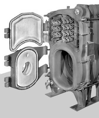
8 1. WARNINGS This handbook, which is divided into two parts, is an essential integral part of the product. Please read all the information carefully as it contains important indications on safety during installation and use. Store this handbook in a safe place for future reference. The boiler must be installed in compliance with current regulations and following the manufacturer's instructions. Wrong installation may cause injury or damage, for which the manufacturer can not be held liable. Unwrap all the parts and check the contents. In case of doubt, do not use the boiler and return it to the supplier. Packaging elements, such as wooden crates, nails, staples, plastic bags and foam plastic, are a hazard and must not be left within the reach of children. This boiler must only be used for the purpose for which it was designed and built. Any other use is considered improper and thus hazardous. The manufacturer can not be held responsible for damage or injury caused by improper or unreasonable use. Before carrying out any cleaning or maintenance operations, always disconnect the boiler from the mains supply. GENERAL RULES Do not obstruct the air intakes or ventilation pipes. If the boiler malfunctions or breaks down, deactivate it immediately. Never attempt to repair it yourself. A professionally qualified person needs to be called in. If any parts need repairing, this must be done by a servicing centre authorised by the manufacturer, using original spare parts. If this is not done, safe operation of the boiler may well be affected. In order to ensure efficiency and correct operation, it is vital to follow the manufacturer's instructions. The boiler must be serviced periodically by a properly qualified person. If you decide not to use the boiler any longer, all parts that are likely to cause a hazard must be rendered harmless. If the boiler is to be sold or transferred to another owner, or if you move and leave the boiler where it is, always check that the handbook remains with the boiler so that it can be consulted by the new owner or installer. Original accessories and spare parts must always be used for boilers with optionals or kits (including electrical ones). WARNING. If there is the risk of freezing, always take the necessary measures, such as adding antifreeze or emptying the system. 2. GENERAL DESCRIPTION (fig. 1) These water boilers with a non-pressurised furnace are built on the basis of advanced principles of heat engineering. In particular, they are very popular due to their high output and considerable cost saving, ease of installation and maintenance, and the fact that they can use any type of approved burner. The boilers described in this manual are designed so that they can be serviced from the front. The burner is mounted on the door which can open to the right or left as required. NOTES: The terms right and left, front and back refer to a person facing the boiler from the door side. The numbers in the descriptions correspond to the numbers shown on the exploded diagrams for assembly and spare parts. The shell of the boiler is comprised of elements arranged in sequence, starting from the front. The combustion chamber "A" (or furnace) is the horizontal cylindrical type on the lower side of the shell. The combustion gases lap the bottom (1) of the furnace, are deflected towards the outer passages of the elements (31) to the front door (20) and then conveyed into the inner passages of the elements (31) before entering the exhaust pipe "B". The circuit of combustion gas is called «three combustion gas passes» and the entire course is surrounded by the water circuit. The boiler shell is thermally insulated and radiation loss is negligible, in full compliance with EN 303 which prescribes maximum temperature for handles and the jacket. MANUFACTURER SERIAL NUMBER MODEL POWER
9 INSTRUCTIONS FOR THE USER 3. APPLICATION The boiler is designed to comply with the following European Directives: 90/396 CEE -Directive concerning gas-fired appliances; 92/42 CEE -Directive concerning boiler efficiency; 73/23 CEE -Directive concerning low voltage appliances; 89/336 CEE -Directive concerning magnetic compatibility. The boiler is designed only for the production of hot water up to 90 C used for heating purposes. So it is equipped with a twostage thermostat with a minimum setting of 43±3 C and a maximum setting of 82±3 C. The features of the boiler and the serial number for identification purposes are shown on the rating plate, which the installer must fix onto the right hand side of the jacket. (See Section «2 -GENERAL DESCRIPTION»). 4. FUEL AND BURNER (fig. 2) Diesel fuel with a max viscosity of 1.4 E at 20 C (NHV kcal/ kg) or natural gas (NHV 8570 kcal/nm 3 ) can be used. The burners are the injection type with maximum head projection as shown in fig.2. The choice of burner depends on the capacity of the boiler and furnace pressure, as shown in the specification. 5. PROPERTIES OF THE WATER The chemical and physical properties of the water in the circuit and top-up water are fundamental factors affecting safety of the system and correct operation of the boiler. Poor quality water is known to cause problems for the entire system, the most serious and most frequent one being the formation of scale on the heat exchanging surfaces. Due to their low heat conductivity, even thin scale deposits insulate the walls, which are not cooled by the circulating water and cause irregular expansion or localised thermal shock. Hence it is advisable to get in touch with a company specialised in water treatment for the development of automatic treatment and control system. Water treatment is necessary when: a) the installations are very large; b) only very hard water is available; c) for any reason the system has to be emptied partially or fully and then needs to be filled again. Properties of the filling and topping-up water are as follows: - Appearance:.clear - Total hardness: max. 20 F - Free oxygen:.max. 0,005 mg/l - Organic substances: max. 0,5 mg/l - ph:..min. 8,5 7. HOW TO OPERATE THE BOILER (figs. 3-4) Starting up Check the pressure on the gauge on the boiler (max 5 bar). Turn the switch (51) to position I. Set the boiler thermostat (50) to the required temperature. Read the boiler water temperature on the thermometer (47). Check operation of the circulation pump. Switching off Turn the boiler thermostat (50) fully anti-clockwise. Allow the boiler to cool down to 50 ± 60 C. Turn the switch (51) to position O to power off the boiler. Emptying If the boiler is not going to be used for a long time and the temperature is low or anti-freeze has not been added, empty the system via the cock (16) which is accessible after removing the upper (43) and lower (42) panels on the front of the jacket. Overheating If the boiler exceeds 100 C, the safety thermostat (52) turns off the burner. Unscrew the cap of the safety thermostat (52) and press the reset button. If the inconvenience occurs again, call in a qualified person to make the necessary repairs. 8. MAINTENANCE AND CLEANING (figs. 4) Once a year at the end of the season, call in a qualified person to service and clean the boiler. However, it will be necessary to clean the boiler whenever alterations in the fuel cause the formation of layers of soot on the heat exchanging surfaces. To clean the boiler, power off from the control panel, open the burner door (18) and the upper door (20). For boilers with 6 and 7 elements, remove the turbofans (27) from the smoke tubes. Remove all soot from the horizontal and vertical pipes using a metal brush and suction device. Alternatively, specific chemical products can be used provided that the instructions on the pack are followed correctly. After cleaning, place the doors back in position carefully, checking the gaskets (35, 36) and insulating panels (17, 22). Check the seal of the burner door and replace the seals if in doubt. NOTE. Cleaning kits are available on request. 6. CONTROL PANEL (fig. 3) The pre-wired control panel comes with the following: ON-OFF switch (51); Heating temperature regulation thermostat (50); Safety thermostat with manual reset (52); Heating water thermometer (47).
10 9. SPECIFICATIONS Model INSTRUCTIONS FOR THE INSTALLER Efficiency class (Dir.Rend.92/42CEE) % Rated output (Pn) kw Nominal thermal capacity (Qn) kw ,4 124,8 144,3 163,6 195,8 217,4 238,6 Efficiency at rated load % 91,1 91,2 91,4 91,6 91,7 91,9 92,0 92,2 Efficiency at 30% load % 92,9 92,9 92,8 92,8 92,7 92,7 92,6 92,6 Flue gas temperature (Ambient temp. 20 C) C , CO 2 G20 gas % 9,6 9,6 9,8 9,9 10,3 10,4 10,7 10,8 Fuel oil % 12,4 12,2 12,3 12,5 12,9 12,9 13,0 13,1 Fuel gas mass output G20 gas kg/h 148, ,8 236,1 266,4 317,1 342,2 372,6 Fuel oil kg/h 140,6 165,1 191, ,8 295,5 325,6 355,1 Heat loss through the casing ( t=50 C) Pd=% 1,3 1,3 1,3 1,2 1,2 1,1 1,0 0,9 Load loss at the stack with burner on Pf=% 7,5 7,4 7,2 7,2 7,1 7,0 7,0 6,9 Load loss at the stack with burner off Pfbs=% 0,1 0,1 0,1 0,1 0,1 0,1 0,1 0,1 Load loss in the combustion circuit pf=pa Load loss on water side ( t=10 C) Pa Load loss on water side ( t=20 C) Pa Number of elements N Boiler weight kg Length of combustion chamber mm Volume of combustion chamber dm³ 64,5 77, ,8 115,6 128,4 141,2 154,0 Volume on flue gas side dm³ 90,5 108, ,8 162,6 180,4 198,2 216,0 Length of the boiler mm Burner coupling diameter mm Flue gas outlet diameter mm 200 Maximum operating pressure Pms=bar 5 Boiler temperature setting range C CH water fitting 2" 1/2 2" Minimum water flow rate lt/h Fuels G20 natural gas or fuel oil 1,4 E-20 C (PCI kcal/kg) Water capacity lt 71,7 82,3 92,9 103,5 114,1 124,7 135,3 145,9 Power supply 2N~230V - 50 Hz - Max.6A 10. OVERALL DIMENSIONS AND FITTINGS (expressed in mm) Ø "B" Model "A" (mm) Ø"B" 2" 1/2 2" 1/2 2" 1/2 2" 1/2 2" 1/2 2" 2" 2" "A" 600
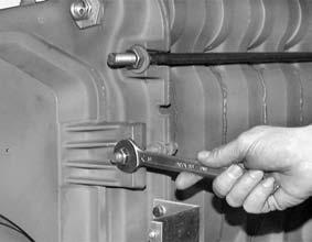
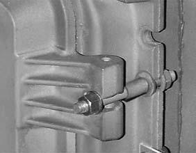
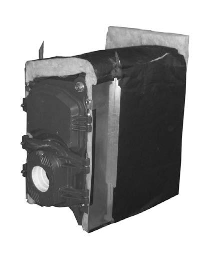
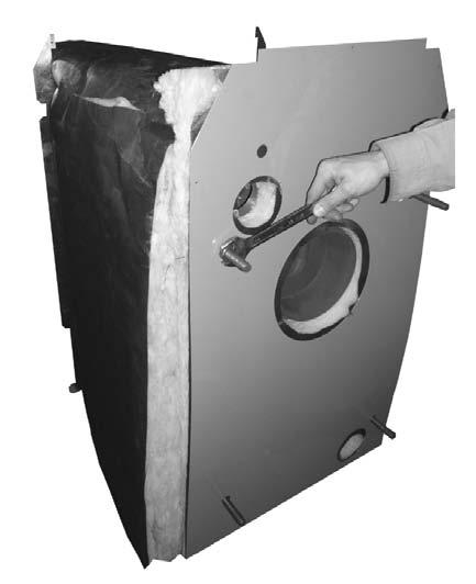
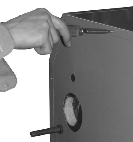
11 11. CONTENTS OF PACKAGE SUPPLIED The following parts are supplied: A: Contains the front element, rear element, intermediate elements (4,11), any turbofans, the gaskets and rings, tierods and assembly guides, doors and accessories. B: Contains the jacket and insulation. C: Contains the lower and upper front panel. D: Contains the instrument support. 12. INSTALLATION (fig. 5) The boiler must be installed by a properly qualified person. It must be installed in a room of a suitable size in compliance with the relevant safety rules. The plumbing system must ensure a minimum flow of water into the boiler as shown in the specification. In the technical data table and the picture 22 the loses of head side water of the boiler are indicated. Figure 5 shows two examples of plumbing system layout. If a sealed expansion tank is used, a safety valve must be fitted. Always remember to comply with any local rules on the safety of heating systems. LEGEND 1 -Open expansion tank 6 -Delivery 2 -Pump 7 -Heating shell 3 -One-way valve 8 -Sealed expansion tank 4 -Re-circulation pump 9 -Filling valve 5 -Return 10 -Safety valve 13. HOW TO INSTALL THE BOILER Boiler installation INVOLVES 4 separate stages. 1. Assembling the boiler shell. 2. Mounting the doors, burner and turbofans (only for boilers with 6 or 7 elements). 3. Mounting the jacket and control panel. 4. Plumbing connections and hydraulic test. NOTE: Distance between Burners axis and Ground is 302 mm, so if the Burner is higher than the normal, a basement of right height is necessary to be mounted underneath the Boiler (at least 150 mm). STAGE 1 - Assembling the boiler shell (figs. 6, 7, 8, 9, 10) 1) Place the slides (8) in the boiler's final position in the room. Fix the rear element (1) to the slides using M10x35 bolts (6, 7, 9). 2) Fill the slots "A" in the flue gas area and edging with the sealant supplied. 3) Mount the containment ring (33) on the hubs with the gasket (32) in a central position. Bring the 1 st intermediate element (31) up to the rear element (1). CAUTION! To keep the elements vertical and parallel, use awire "B" wound round the upper hubs. 4) Repeat steps 2 and 3 for all the intermediate elements (31) and the front element (30). 5) Insert the tie-rods (10) with the shorter threaded part "C" towards the front. Centre the 17x34x4.2 washers (5) and screw in the nuts (4) by hand. 6) Inlet and outlet distributor (37, 38 fig.23) must be mounted screwing them upon threads on the rear section. This operation must to be absolutely set before clenching the Boiler body. 7) Tighten the nuts (4) alternately until the elements come into contact. Complete the operation with a dynamometric spanner set to 5 kgm (* 50 Nm). 8) Mount the 1 1/4" adapters (15) on the front element (30) the sheath (28) for the probes in the upper adapter and the drain cock (16) in the lower one. STAGE 2 -Mounting the doors and burner (figs. 12, 2) 1) Apply the insulating cord (35) (ø12x1300) to the upper door (20) and the insulating cord (36) (ø 12x1070) to the lower door (18). Insert them by knocking slightly with a mallet and make a joint "D" at the bottom of the door. 2) Determine which side the doors (20, 18) are to open. Mount the M12x130 tie-rods (23) using the nuts (11) and washers (12). On the other side mount the eyebolts (13) and tighten them temporarily using the nuts (11) and washers (12). 3) Mount the cleaning door (20) and burner door (18), locking them in the eyebolts (13) by means of the respective pins (29, 14). CAUTION! After inserting the pins, remember to tighten the eyebolts (13) fully. 4) Only for boilers with 6 or 7elements: fit the turbofans (27) (n. 4 for 6 elements and n. 2 for 7 elements) NOTE: Turbofans for 7-element boilers must be inserted in the central flue gas passages. 5) Close the doors and tighten the brass nuts (21). CAUTION! Check carefully that the doors close properly. STAGE 3 - Mounting the jacket and control panel (figs. 2, 12, 13, 14, 15, 16, 17, 18, 19) 1) Cover the boiler shell with layers of insulation (57) making sure the bottom one is centred and adheres properly. 2) Mount the brackets (24, 25) on the front element and lock them with nuts M16 (26). 3) Fit the insulating panel (58) onto the rear element (1), centring the holes in the tie-rods (10). 4) Mount the rear panel (63), centring the holes in the tierods (10). 5) Mount the sides (40, 55) of the jacket. 6) Lock the sides onto the brackets (24, 25) and to the rear panel (63) using the screws (65). 7) Secure the control panel (45) onto the instrument support (46) using the four screw (44) 8) Unwind the capillaries of the thermostats (50, 52) and the thermometer (47). Insert the probes in the sheath (28) and tighten them with the probe retaining spring. CAUTION! When unwinding the capillaries, be very careful not to create sharp bends or twists. 9) Mount the complete control panel onto the side panel (40, 55) centring the holes and secure it with the screws (65). 10) Connect the cable of the power supply, insert this in the wire lead and lock this in position. CAUTION! Connect all earthing cables to the screw. 11) Lastly, mount the top panel (56) and the front panel (43, 42) in that order. 12) Stick the rating plate on to the right-hand side panel (40) of the jacket. STAGE 4 -Plumbing connections and hydraulic test Fill the boiler and carry out a hydraulic test in compliance with the European standard EN The test pressure must be 6.5 bar. 14. CONNECTING TO THE STACK The products of combustion must be discharged through a pipe with a diameter at least that of the flue gas pipe, connected to a stack with a suitable capacity. The cross section and height of the stack must guarantee the minimum draft specified and the thermal insulation must comply with the relevant standards. The SPECIFICATION table shows load loss values on the gas side for each model of boiler. 15. INSTALLING THE BURNER (fig. 2) The lower panel (18) has a coupling for the burner. For 6 10 sections 4 coupling M8 on Ø170 are used. For sections two different coupling are used: N 4 of M8 Ø170 centre distance N 4 of M10 Ø240 centre distance. It is advisable to graphitize the burner screws to facilitate removal later on. If the burner has a flange that can not be adapted to the fitting, an adapter is required plus an insulation panel. The diameter of the burner head may differ from that of the insulation, in which case the hole must be adapted as accurately as possible to prevent backfiring. The maximum diameter allowed is 150 mm.
12 16. REGULATING THERMAL POWER The Burner must be able to give required thermic output and overcome the pressurization of the combustion chamber. The boiler's thermal power must be regulated according to the requirements of the system. Read the burner instructions very carefully and regulate the fuel pressure to get the required value. 17. WIRING Connect the power cable to the control panel of the heating plant. To connect the burner, follow the instructions in the booklet provided with the burner. CAUTION! must be earthed. 18. FILLING AND STARTING UP THE SYSTEM (fig. 3) Fill the system slowly to get out all the air. Charge the system until the operating pressure is reached (maximum 5 bar). Operate the master switch on the heating system. Turn the control (51) to position I. Set the boiler thermostat (50) to the required temperature. Check that the system and circulation pumps work properly.
13 SPARE PARTS CATALOGUE Posn. Code Description Posn. Code Description Rear element Turbofan ( 82-98) Nut Fe M16 H Sheath 3/4"x360-3 cavities Flat washer Fe Ø 17x30x Flathead pin 10x Nut Fe M16 H Front element Tapered washer Ø17x34x Intermediate element 6 Screw Fe M10x Hub gasket 7 Flat washer Ø Hub gasket containment ring Support guide for Insulating cord Ø12x Support guide for Insulating cord Ø12x Support guide for Inlet distributor ( ) Support guide for Inlet distributor ( 220) Support guide for Outlet distributor ( ) Support guide for * RH side panel Support guide for # Lower front panel Support guide for # Upper front panel Flanged nut M10 44 Control panel screw Tie-rod M16x845 ( 82) 45 Control panel Tie-rod M16x965 ( 98) Control panel support Tie-rod M16x1090 ( 114) 47 Thermometer Tie-rod M16x1210 ( 132) 50 Regulation thermostat Tie-rod M16x1330 ( 150) 51 ON - OFF / Switch Tie-rod M16x1450 ( 180) 52 Safety thermostat with manual reset Tie-rod M16x1570 ( 200) 53 Fuse Tie-rod M16x1690 ( 220) 55 * LH side panel 11 Nut Fe M12 H10 56 * Top cover 12 Flat washer Ø13x24x2,5 57 * Boiler body insulation Eyebolt M12x * Boiler body rear insulation Flathead pin 10x80 63 * Rear panel Adapter 1"1/4x3/4" with beat 65 * Self-tapping screw 4.2x9,5 16 Drain cock 3/4" M Burner door insulation * Complete jacket Burner door * Complete jacket Plug 3/4" * Complete jacket Cleaning door * Complete jacket Brass nut M12 * Complete jacket Cleaning door insulation * Complete jacket Tie-rod M12x130 * Complete jacket * RH jacket bracket * Complete jacket * LH jacket bracket 26 * Nut Fe M16 H8 # Front panel
14 kw MANTEMENIOI ΛΕΒΗΤΕΣ ΠΕΤΡΕΛΑΙΟΥ ΑΕΡΙΟΥ ΕΓΧΕΙΡΙ ΙΟ ΕΓΚΑΤΑΣΤΑΣΗΣ ΚΑΙ ΣΥΝΤΗΡΗΣΗΣ AS2413
15 1. ΠΡΟΕΙ ΟΠΟΙΗΣΕΙΣ Αυτό το εγχειρίδιο, που διαιρείται σε δύο µέρη, είναι ένα ουσιαστικό αναπόσπαστο τµήµα του προϊόντος. Παρακαλούµε διαβάστε όλες τις πληροφορίες προσεκτικά δεδοµένου ότι περιέχουν σηµαντικές πληροφορίες για την ασφάλεια κατά τη διάρκεια της εγκατάστασης και της χρήσης. Φυλάξτε αυτό το εγχειρίδιο σε µια ασφαλή θέση για µελλοντική χρήση. Ο λέβητας πρέπει να εγκατασταθεί σύµφωνα µε τους τρέχοντες κανονισµούς και τις οδηγίες του κατασκευαστή. Η λανθασµένη εγκατάσταση µπορεί να προκαλέσει τραυµατισµό ή ζηµία, για τα οποία ο κατασκευαστής δεν φέρει καµία ευθύνη. Ανοίξτε όλα τα µέρη και ελέγξατε το περιεχόµενο. Σε περίπτωση αµφιβολίας, µην χρησιµοποιήστε το λέβητα και επιστρέψτε τον στον προµηθευτή. Τα υλικά συσκευασίας, όπως τα ξύλα, καρφιά, βάσεις, πλαστικές τσάντες και αφρολέξ, είναι επικίνδυνα και δεν πρέπει να είναι προσιτά στα παιδιά. Αυτός ο λέβητας πρέπει να χρησιµοποιηθεί µόνο για το σκοπό για τον οποίο σχεδιάστηκε. Οποιαδήποτε άλλη χρήση θεωρείται ανάρµοστη και επικίνδυνη. Ο κατασκευαστής δεν µπορεί να θεωρηθεί υπεύθυνος για τη ζηµία ή τον τραυµατισµό που προκαλείται από ανάρµοστη ή αδικαιολόγητη χρήση. Πρίν γίνει οποιαδήποτε διαδικασία καθαρισµού ή συντήρησης, αποσυνδέστε πάντα το λέβητα από την ηλεκτρική παροχή. ΓΕΝΙΚΟΙ ΚΑΝΟΝΕΣ Μην εµποδίστε τους αεραγωγούς εισαγωγής ή τους σωλήνες εξαερισµού. Εάν ο λέβητας δυσλειτουργεί ή παθαίνει βλάβη, απενεργοποιήστε τον αµέσως. Μην προσπαθείτε να τον επισκευάσετε οι ίδιοι. Ένα επαγγελµατικά καταρτισµένο άτοµο πρέπει να κληθεί. Εάν οποιαδήποτε µέρη χρειάζονται επισκευή, αυτό πρέπει να γίνει από εξουσιοδοτηµένα άτοµα που έχουν εγκριθεί από τον κατασκευαστή, χρησιµοποιώντας γνήσια ανταλλακτικά. Εάν αυτό δεν γίνει, η ασφαλής λειτουργία του λέβητα µπορεί να επηρεαστεί. Προκειµένου να εξασφαλιστούν η αποδοτικότητα και η σωστή λειτουργία, είναι ζωτικής σηµασίας να ακολουθηθούν οι οδηγίες του κατασκευαστή. Ο λέβητας πρέπει να συντηρηθεί περιοδικά από ένα κατάλληλα καταρτισµένο πρόσωπο. Εάν αποφασίσετε να µην χρησιµοποιήσετε άλλο το λέβητα, όλα τα µέρη που είναι πιθανό να προκαλέσουν ζηµία, πρέπει να κατασταθούν αβλαβή. Εάν ο λέβητας πρόκειται να πωληθεί ή να µεταφερθεί σε έναν άλλο ιδιοκτήτη, το εγχειρίδιο πρέπει να παραµένει µε το λέβητα έτσι ώστε να µπορεί να χρησιµοποιηθεί από το νέο ιδιοκτήτη. Πάντα πρέπει να χρησιµοποιούνται γνήσια εξαρτήµατα και ανταλλακτικά για τους λέβητες. ΠΡΟΕΙ ΟΠΟΙΗΣΗ. Εάν υπάρχει κίνδυνος παγοποίησης, λάβετε πάντα τα απαραίτητα µέτρα, όπως η προσθήκη αντιψυκτικού ή η εκκένωση του συστήµατος. 2. ΓΕΝΙΚΗ ΠΕΡΙΓΡΑΦΗ (Εικ. 1) Αυτός ο λέβητας, που αποτελείται από στοιχεία µε βρεχόµενες διαδροµές χυτοσιδήρου και σχεδιάστηκε για να λειτουργήσει µε κενό για τα πρότυπα µε 3..4 και 5 στοιχεία και µε πίεση για τα επόµενα πρότυπα, συµµορφώνεται πλήρως µε τις πιό πρόσφατες αρχές εφαρµοσµένης θερµοδυναµικής. Ειδικότερα φηµίζονται, για την πολύ υψηλή απόδοση και συνεπώς την οικονοµική τους λειτουργία, την ευκολία της εγκατάστασης και της συντήρησης και το γεγονός ότι µπορούν να χρησιµοποιήσουν οποιοδήποτε τύπο εγκεκριµένου καυστήρα. Ο λέβητας που περιγράφεται σε αυτό το εγχειρίδιο σχεδιάστηκε έτσι ώστε να µπορεί να συντηρηθεί από µπροστά. Ο καυστήρας τοποθετείται στην πόρτα που µπορεί να ανοίξει δεξιά ή αριστερά ανάλογα µε την απαίτηση. ΣΗΜ. Οι όροι, δεξιά και αριστερά, µέτωπο και πλάτη αναφέρονται σε ένα πρόσωπο που βλέπει το λέβητα από τις πόρτες. Οι αριθµοί στις περιγραφές αντιστοιχούν στους αριθµούς που παρουσιάζονται στα διαγράµµατα για τη συναρµλόγηση και τα ανταλλακτικά. Ο λέβητας αποτελείται από στοιχεία εν σειρά αρχίζοντας από µπροστά. Ο θάλαµος καύσης "Α" είναι οριζοντίου κυλινδρικού τύπου και βρίσκεται στο κατώτατο σηµείο του λέβητα. Τα καυσαέρια διατρέχουν τον θάλαµο καύσης(1), έρχονται σε επαφή µε τον «καθρέφτη», εκτρέπονται στις δευτερεύουσες διαδροµές (31) µέχρι την µπροστινή πόρτα(20), έπειτα µεταβιβάζονται στις εσωτερικές διαδροµές των στοιχείων (31) πριν καταλήξουν στον αγωγό καυσαερίων"b". Αυτό το κύκλωµα µε την τριπλή διαδροµή των καυσαερίων και τις πλήρως βρεχόµενες επιφάνειες, διασφαλίζει την βέλτιστη εναλλαγή θερµότητας. Ο κάδος του λέβητα είναι θερµικά µονωµένος µε ένα παχύ στρώµα µονωτικού, που διατηρεί τις απώλειες ελάχιστες, σε πλήρη συµµόρφωση µε το EN 303 που ορίζει τη µέγιστη θερµοκρασία για τις λαβές και τα καλύµµατα. MANUFACTURER MODEL SERIAL NUMBER POWER
16 3. ΕΦΑΡΜΟΓΗ Ο ΗΓΙΕΣ ΓΙΑ ΤΟΝ ΧΡΗΣΤΗ Ο λέβητας σχεδιάστηκε σύµφωνα µε τις ακόλουθες ευρωπαϊκές οδηγίες: 90/396 CEE Οδηγία σχετικά µε τις συσκευές αερίου; 92/42 CEE Οδηγία σχετικά µε την αποδοτικότητα λεβήτων; 73/23 CEE Οδηγία σχετικά µε τις συσκευές χαµηλής τάσης; 89/336 CEE Οδηγία σχετικά µε τη µαγνητική συµβατότητα. Ο λέβητας σχεδιάστηκε µόνο για την παραγωγή ζεστού νερού µέχρι 90 C που χρησιµοποιείται για λόγους θέρµανσης. Ο λέβητας µπορεί να συνδεθεί µε Boiler για την παραγωγή ζεστού νερού χρήσης. Τα χαρακτηριστικά γνωρίσµατα του λέβητα και ο αύξων αριθµός για λόγους προσδιορισµού, αναφέρονται στο πίνακα τεχνικών προδιαγραφών, ο οποίος πρέπει να κολληθεί επάνω στη δεξιά πλευρά του καλύµµατος. ( είτε το τµήµα "2 - ΓΕΝΙΚΗ ΠΕΡΙΓΡΑΦΗ»). 4. ΚΑΥΣΙΜΑ ΚΑΙ ΚΑΥΣΤΗΡΑΣ (Εικ. 2) Τα καύσιµα, diesel µε ένα ανώτατο ιξώδες 1.4 E σε 20 C (NHV kcal/kl) ή το φυσικό αέριο (NHV 8570 kcal/*nm 3 ) µπορούν να χρησιµοποιηθούν. Οι καυστήρες πρέπει να είναι πιεστικού τύπου και να έχουν µπούκα που είναι ελαφρώς µακρύτερη από το πάχος µόνωσης, όπως φαίνεται στο σχήµα 2. Η επιλογή του καυστήρα εξαρτάται από την ισχύ του λέβητα και τις απώλειες στα καυσαέρια, όπως φαίνεται στον πίνακα των προδιαγραφών. 5. Ι ΙΟΤΗΤΕΣ ΤΟΥ ΝΕΡΟΥ Οι χηµικές και φυσικές ιδιότητες του νερού στο κύκλωµα, είναι θεµελιώδεις παράγοντες που έχουν επιπτώσεις στην ασφάλεια του συστήµατος και στη σωστή λειτουργία του λέβητα. Το κακής ποιότητας νερό, είναι γνωστό ότι προκαλεί προβλήµατα σε ολόκληρο το σύστηµα. Το σοβαρότερο και το συχνότερο είναι οι επικαθίσεις αλάτων στις επιφάνειες θερµικής µεταφοράς. Λόγω της χαµηλής αγωγιµότητας θερµότητάς τους, ακόµη και οι λεπτές επικαθίσεις αλάτων, µονώνουν τα τοιχώµατα, οι οποίοι δεν δροσίζονται από το νερό που κυκλοφορεί και προκαλούν την ανώµαλη επέκταση ή το εντοπισµένο θερµικό σοκ. Έτσι είναι απαραίτητο να χρησιµοποιηθεί κατάλληλα αποσκληρυµένο νερό, εάν η σκληρότητα του είναι πάνω από F. Η αποσκλήρυνση ύδατος είναι απαραίτητη όταν: a) οι εγκαταστάσεις είναι πολύ µεγάλες; b) µόνο το πολύ σκληρό νερό είναι διαθέσιµο; c) για οποιοδήποτε λόγο το σύστηµα πρέπει να εκκενωθεί µερικώς ή πλήρως και έπειτα πρέπει να πληρωθεί ξανά. Οι ιδιότητες του ύδατος πλήρωσης πρέπει να είναι οι ακόλουθες: - Εµφάνιση:. καθαρό - Συνολική σκληρότητα:. max. 20 F - Ελεύθερο οξυγόνο:..max. 0,005 mg/l - Οργανικές ουσίες: max. 0,5 mg/l PH. min 8,5 6. ΠΙΝΑΚΑΣ ΕΛΕΓΧΟΥ (Εικ. 3) Ο πίνακας ελέγχου έχει τα παρακάτω : ON-OFF διακόπτης (51); θερµοστάτης ελέγχου θερµοκρασίας (50); Θερµοστάτης ασφάλειας µε manual επαναφορά (52); Θερµόµετρο ύδατος (47). 7. ΠΩΣ ΝΑ ΛΕΙΤΟΥΡΓΗΣΕΤΕ ΤΟ ΛΕΒΗΤΑ (Εικ. 3-4) Ξεκίνηµα Ελέγξτε την πίεση στο µανόµετρο στο λέβητα (max 5 bar). Ανοίξτε όλες τις βάνες του συστήµατος θέρµανσης και το σύστηµα παροχής καυσίµου. Γυρίστε το διακόπτη (51) στη θέση I. Θέστε στο θερµοστάτη (50) την επιθυµητή θερµοκρασία. ιαβάστε τη θερµοκρασία νερού στο θερµόµετρο (47). Ελέγξατε τη λειτουργία του κυκλοφορητή. Σβήσιµο Γυρίστε τη θερµοστάτη του λέβητα(50) πλήρως σε αντίθετη φορά προς την φορά των δεικτών του ρολογιού. Επιτρέψτε στο λέβητα για να κρυώσει κάτω από C. Γυρίστε το διακόπτη (51) στη θέση O για να σβήσει. Εκκένωση Εάν ο λέβητας δεν πρόκειται να χρησιµοποιηθεί για πολύ και η θερµοκρασία είναι χαµηλή ή αντιψυκτικό δεν έχει προστεθεί, αδειάστε το σύστηµα από τη βάνα (16) η όποία είναι προσιτή µετά από την αφαίρεση του άνω (43) και κάτω (42) µπροστινού καλύµµατος. Υπερθέρµανση Εάν ο λέβητας υπερβεί τους 100 C, ο θερµοστάτης ασφάλειας (52) κλείνει τον καυστήρα. Ξεβιδώστε το καπάκι του θερµοστάτη ασφάλειας (52) και πιέστε το κουµπί επαναφοράς. Εάν το πρόβληµα εµφανίζεται πάλι, καλέστε ένα καταρτισµένο τεχνικό για να κάνει τις απαραίτητες επισκευές. 8. ΣΥΝΤΗΡΗΣΗ ΚΑΙ ΚΑΘΑΡΙΣΜΟΣ (Εικ. 4) Είναι ενδεδειγµένο να υπογραφεί µια ετήσια σύµβαση συντήρησης µε εξειδικευµένο τεχνικό για να καθαρίζει το λέβητα. Εντούτοις, θα είναι απαραίτητο να καθαριστεί ο λέβητας όποτε οι αλλαγές στα καύσιµα προκαλούν το σχηµατισµό στρωµάτων αιθάλης στη επιφάνειες εναλλαγής θερµότητας. Για να καθαρίσετε το λέβητα, θέσατε τον διακόπτη στη θέση OFF, ανοίξατε την πόρτα του καυστήρα (18) και την πάνω πόρτα (20). Για τους λέβητες µε 6 και 7 στοιχεία, αφαιρέστε τους επιβραδυντές (27) από τις διαδροµές καυσαερίων. Καθαρίστε την αιθάλη από τις διαδροµές και το θάλαµο καύσης, χρησιµοποιώντας µια βούρτσα µετάλλων και µια συσκευή αναρρόφησης. Εναλλακτικά, συγκεκριµένα χηµικά προϊόντα µπορούν να χρησιµοποιηθούν υπό τον όρο ότι οι οδηγίες ακολουθούνται σωστά. Μετά τον καθαρισµό, τοποθετήστε τις πόρτες στη θέση τους προσεκτικά, ελέγχοντας για τη σωστή θέση των gaskets (35, 36) και των µονωτικών πλακών (17, 22). Ελέγξτε τη µόνωση του καυστήρα και της πάνω πόρτας και αντικαταστήστε τις µονώσεις αν υπάρχει αµφιβολία ΣΗΜΕΙΩΣΗ. ΚΙΤ καθαρισµού είναι διαθέσιµα κατόπιν αιτήσεως.
17 9. ΠΡΟ ΙΑΓΡΑΦΕΣ Μοντέλο Ο ΗΓΙΕΣ ΓΙΑ ΤΟΝ ΕΓΚΑΤΑΣΤΑΤΗ Κλάση Απόδοσης (Dir. Rend. 92/42CEE) % Ισχύς εξόδου (Pn) kw Ονοµαστική θερµική ισχύς (Qn) kw ,4 124,8 144,3 163,6 195,8 217,4 238,6 Απόδοση σε ονοµαστικό φορτίο % 91,1 91,2 91,4 91,6 91,7 91,9 92,0 92,2 Απόδοση σε 30% φορτίο % 92,9 92,9 92,8 92,8 92,7 92,7 92,6 92,6 Θερµοκρασία εξόδου καυσαερίων. (20 C) C , CO 2 G20 gas % 9,6 9,6 9,8 9,9 10,3 10,4 10,7 10,8 Fuel oil % 12,4 12,2 12,3 12,5 12,9 12,9 13,0 13,1 Παραγόµενη µάζα G20 gas kg/h 148, ,8 236,1 266,4 317,1 342,2 372,6 καυσαερίων Fuel oil kg/h 140,6 165,1 191, ,8 295,5 325,6 355,1 ιασπορά µέσω του περιβλήµατος ( t=50 C) Pd=% 1,3 1,3 1,3 1,2 1,2 1,1 1,0 0,9 Απώλειες στην καµινάδα µε καυστήρα ΟΝ Pf=% 7,5 7,4 7,2 7,2 7,1 7,0 7,0 6,9 Απώλειες στην καµινάδα µε καυστήρα ΟFF Pfbs=% 0,1 0,1 0,1 0,1 0,1 0,1 0,1 0,1 Απώλεια φορτίου στο κύκλωµα καύσης pf=pa Απώλεια φορτίου στο νερό ( t=10 C) Pa Απώλεια φορτίου στο νερό ( t=20 C) Pa Αριθµός στοιχείων N Βάρος λέβητα kg Μήκος του θαλάµου καύσης mm Όγκος του θαλάµου καύσης dm³ 64,5 77, ,8 115,6 128,4 141,2 154,0 Όγκος του καπναγωγού dm³ 90,5 108, ,8 162,6 180,4 198,2 216,0 Μήκος του λέβητα mm ιατοµή οπής καυστήρα mm ιατοµή καπναγωγού mm 200 Μέγιστη πίεση Λειτουργίας Pms=bar 5 Επιλογή θερµοκρασίας λειτουργίας C ιατοµή σύνδεσης Θέρµανσης 2" 1/2 2" Ελάχιστη ροή νερού lt/h Καύσιµα G20 natural gas or fuel oil 1,4 E-20 C (PCI kcal/kg) Χωρητικότητα ύδατος lt 71,7 82,3 92,9 103,5 114,1 124,7 135,3 145,9 Παροχή ηλεκτρικού ρεύµατος 2N~230V - 50 Hz - Max.6A 10. ΓΕΝΙΚΕΣ ΙΑΣΤΑΣΕΙΣ (εκφρασµένες σε mm) Ø "B" Model "A" (mm) Ø"B" 2" 1/2 2" 1/2 2" 1/2 2" 1/2 2" 1/2 2" 2" 2" "A" 600
18 11. ΠΑΡΕΧΟΜΕΝΑ ΣΤΟ ΠΑΚΕΤΟ Τα ακόλουθα µέρη παρέχονται: A: Στοιχεία του λέβητα (µπροστινό, πίσω και ενδιάµεσα(4,11)), επιβρανδυτές, πόρτες, ράβδοι σύνδεσης και άλλα accessories. B: Tα καλύµµατα και τις µονώσεις C: Άνω και κάτω µπροστινό κάλυµµα D: Πίνακας ελέγχου 12. ΕΓΚΑΤΑΣΤΑΣΗ (Εικ. 5) Ο λέβητας πρέπει να εγκατασταθεί από ένα κατάλληλα καταρτισµένο πρόσωπο. Πρέπει να εγκατασταθεί σε ένα δωµάτιο κατάλληλου µεγέθους, σύµφωνα µε τους σχετικούς κανόνες ασφάλειας. Το σύστηµα υδραυλικών εγκαταστάσεων πρέπει να εξασφαλίσει µια ελάχιστη ροή του ύδατος στο λέβητα όπως φαίνεται στην προδιαγραφή. Στo πίνακα τεχνικών χαρακτηριστικών και στην εικόνα 22 φαίνονται οι απώλειες στο κύκλωµα καύσης. Η εικ. 5 δείχνει δύο παραδείγµατα υδραυλικής εγκατάστασης. Εάν χρησιµοποιείται κλειστό δοχείο διαστολής, µια βαλβίδα ασφάλειας πρέπει να εγκατασταθεί. Πάντα θυµηθείτε να συµµορφώνεστε µε τους τοπικούς κανόνες για την ασφάλεια των συστηµάτων θέρµανσης. ΕΠΕΞΗΓΗΣΕΙΣ 1 - Ανοικτό δοχείο διαστολής 6 - Προσαγωγή 2 - Κυκλοφορητής 7 - Εναλλάκτης 3 - Απλή βάνα 8 - Κλειστό δοχείο διαστολής 4 Κυκλοφ.ανακυκλοφορίας 9 - Βαλβίδα πληρώσεως 5 - Επιστροφή 10 - Βαλβίδα ασφαλείας 13. ΕΓΚΑΤΑΣΤΑΣΗ ΤΟΥ ΛΕΒΗΤΑ Ο λέβητας εγκαθίσταται σε 4 ξεχωριστά στάδια: 1. Συναρµολόγηση στοιχείων 2. Σύνδεση των πόρτων, καυστήρα και επιβραδυντών (µόνον για λέβητες µε 6 ή 7 στοιχεία) 3. Συναρµολόγηση των καλυµµάτων και του πίνακα ελέγχου. 4. Συνδέσεις υδραυλικών και υδραυλική δοκιµή ΣΗΜΕΙΩΣΗ: Η απόσταση µεταξύ του άξονα του καυστήρα και του εδάφους είναι 302 χιλ., έτσι εάν ο καυστήρας είναι υψηλότερος από το κανονικό, µία βάση είναι απαραίτητο να τοποθετηθεί κάτω από το λέβητα (τουλάχιστον 150 χιλ.). ΣΤΑ ΙΟ 1 - Συναρµολόγηση των στοιχείων του λέβητα (Εικ. 6, 7, 8, 9, 10) 1) Τοποθετήστε τους οδηγούς (8) στην τελική θέση του λέβητα στο χώρο και βάλτε το οπίσθιο στοιχείο (1) στους οδηγούς χρησιµοποιώντας τα µπουλόνια M10x35 (6..7, 9) 2) Γεµίστε τις αυλακώσεις "Α " µε τη παρεχόµενη στεγανωτική ουσία. 3) Τοποθετήστε το δαχτυλίδι συγκράτησης (33) στις πλήµνες µε το gasket (32) επικεντρωµένο. Φέρτε στο 1 ο ενδιάµεσο στοιχείο (31) µέχρι το οπίσθιο στοιχείο (1). ΠΡΟΣΟΧΗ! Κρατήσετε τα στοιχεία κάθετα και παράλληλα, χρησιµοποιώντας ένα σύρµα "Β" και περιτυλίξτε το γύρω από τις πάνω πλήµνες. 4) Επαναλάβετε τα βήµατα 2 και 3 για όλα τα ενδιάµεσα στοιχεία (31) και το µπροστινό στοιχείο (30). 5) Τοποθετήστε τις ράβδους (10) προς το µέτωπο " C ". Κεντροθετήστε τις 17x34x4.2 ροδέλες (5) και βιδώστε τα παξιµάδια (4) µε το χέρι. 6) Ο διανοµέας εισαγωγής και εξόδου ( σχέδιο 23) πρέπει να βιδωθεί στο οπίσθιο τµήµα. Αυτή η εργασία πρέπει να γίνει απολύτως πρίν την σύσφιξη των στοιχείων. 7) Σφίξτε τα παξιµάδια (4) διαδοχικά έως ότου τα στοιχεία έλθουν σε επαφή. Ολοκληρώστε τη εργασία µε ένα δυναµοµετρικό κλειδί ρυθµισµένο στα 5 kgm (* 50 NM). 8) Τοποθετήστε τα 1 1/4" ρακόρ (15) στο µπροστινό στοιχείο (30), τον υποδοχέα( 28) για τα αισθητήρια στο επάνω ρακόρ και τη βάνα αποστράγγισης (16) στο κάτω. ΣΤΑ ΙΟ 2 - Τοποθέτηση πόρτων και καυστήρα (Εικ. 12, 2) 1. Εφαρµόστε το κορδόνι µόνωσης (35) (ø12x1300) στην πάνω πόρτα (20) και το κορδόνι µόνωσης (36) (ø 12x1070) στην κάτω πόρτα (18). Περάστε το χτυπώντας το ελαφρώς µε ένα σφυρί και κάνετε την ένωση "D" στο κατώτατο σηµείο της πόρτας. 2.Προσδιορίστε προς τα πού θέλετε να ανοίγουν οι πόρτες (20, 18). Τοποθετήστε τις M12x130 ράβδους σύσφιξης (23) χρησιµοποιώντας τα παξιµάδια(11) και τις ροδέλες (12). Από την άλλη πλευρά τοποθετήστε τους κοχλίες (13) και σφίξτε τα σταδιακά, χρησιµοποιώντας τα παξιµάδια (11) και τις ροδέλες (12). 3.Στηρίξτε την πόρτα καθαρισµού (20) και την πόρτα του καυστήρα (18), ασφαλίζοντας αυτές στον κοχλία (13) µε τη χρήση του άξονα ασφαλείας (29, 14). ΠΡΟΣΟΧΗ! Μετά την εισαγωγή του άξονα, σφίξτε τους κοχλίες (13) πλήρως. 4.Μόνο για τους λέβητες µε 6 ή 7 στοιχεία: εγκαταστήστε επιβραδυντές(27) (n. 4 για 6 στοιχεία και n. 2 για 7 στοιχεία) ΣΗΜΕΙΩΣΗ: Επιβραδυντές για τους λέβητες 7-στοιχείων πρέπει να παρεµβληθούν στις κεντρικές διαδροµές 5... Κλείστε τις πόρτες και σφίγξτε τα παξιµάδια ορείχαλκου (21). ΠΡΟΣΟΧΗ! Ελέγξατε προσεκτικά οι πόρτες να κλείνουν κατάλληλα. ΣΤΑ ΙΟ 3 - Συναρµολόγηση καλυµµάτων και πίνακα ελέγχου (Εικ. 2, 12, 13, 14, 15, 16, 17, 18, 19) 1) Καλύψτε το λέβητα µε τη µόνωση (57) σιγουρευτείτε ότι είναι κεντροθετηµένη και στερεωµένη κατάλληλα. 2) Τοποθετήστε τα υποστηρίγµατα (24, 25) στο µπροστινό στοιχείο και ασφαλίστε τα µε τα παξιµάδια M16 (26). 3) Εγκαταστήστε τη µόνωση (58) επάνω στο οπίσθιο στοιχείο (1), µε κεντροθετηµένες τις τρύπες (10). 4) Τοποθετήστε το οπίσθιο κάλυµµα (63), κεντροθετώντας τις τρύπες στα σηµεία σύνδεσης (10). 5) Τοποθετήστε τα πλευρικά καλύµµατα (40, 55). 6) Ασφαλίστε τα πλευρικά καλύµµατα στις συνδέσεις(24, 25) και στο πίσω κάλυµµα (63) χρησιµοποιώντας τις βίδες (65). 7) Ασφαλίστε τον πίνακα (45) στο µπροστινό πλαίσιο (46) χρησιµοποιώντας τις τέσσερις βίδες (44) 8) Ξετυλίξτε τα τριχοειδή αγγεία των θερµοστατών (50, 52) και του θερµοµέτρου (47). Παρεµβάλτε τους αισθητήρες στη θήκη (28) και σφίγξτε τους µε το ελατήριο σύσφιξης. ΠΡΟΣΟΧΗ! Ξετυλίγοντας τα τριχοειδή αγγεία, να είστε πολύ προσεκτικοί για να µην τσακίσετε τα σωληνάκια. 9) Τοποθετήστε τον πίνακα θέση του (40, 55) κεντροθετώντας τις τρύπες και ασφαλίζοντάς τον µε δύο βίδες (65). 10) Συνδέστε το καλώδιο της παροχής ηλεκτρικού ρεύµατος, περάστε το στον πίνακα και ασφαλίστε το. ΠΡΟΣΟΧΗ! Συνδέστε όλα τα καλώδια γείωσης στη βίδα. 11) Τελικά, τοποθετήστε το επάνω καπάκι (56) και το µπροστινό (43, 42) µε την σειρά. 12) Κολλήστε τον πίνακα µε τα τεχνικά χαρακτηριστικά στη δεξιά πλευρά (40) του λέβητα. ΣΤΑ ΙΟ 4 - Υδραυλική σύνδεση και υδραυλική δοκιµή Γεµίστε το λέβητα και πραγµατοποιήστε µια υδραυλική δοκιµή σύµφωνα µε το ευρωπαϊκό πρότυπο EN Η πίεση δοκιµής πρέπει να είναι 6,5 ΒΑR. 14.ΣΥΝ ΕΣΗ ΜΕ ΤΗΝ ΚΑΜΙΝΑ Α Τα προϊόντα της καύσης πρέπει να µεταφερθούν µέσω ενός καπναγωγού µε διάµετρο τουλάχιστον ίδιας µε αυτή της καµινάδας που θα συνδεθεί και θα καλύπτει την απαίτηση του λέβητα. Το οριζόντιο τµήµα και ύψος της καµινάδας, πρέπει να εγγυάται τον ελάχιστο ελκυσµό που απαιτείται και τη θερµική µόνωση, σύµφωνα µε τα σχετικά πρότυπα. Ο πίνακας ΠΡΟ ΙΑΓΡΑΦΩΝ εµφανίζειι τιµές απώλειας φορτίων στα καυσαέρια, για κάθε πρότυπο του λέβητα. 15.ΕΓΚΑΤΑΣΤΑΣΗ ΤΟΥ ΚΑΥΣΤΗΡΑ (Εικ. 2) Το κάτω κάλυµµα (18) έχει µια σύζευξη για τον καυστήρα. Για 6-10 στοιχεία No 4 σύζευξη M8 Ǿ 170 χρησιµοποιούνται. Για στοιχεία, δύο διαφορετικές διατοµές χρησιµοποιείται: N 4 M8 Ǿ 170 διάµετρο N 4 M10 Ǿ 240 διάµετρο. Είναι ενδεδειγµένο να λιπαίνονται οι βίδες των καυστήρων για να διευκολύνεται η αφαίρεση τους όταν απαιτηθεί. Εάν ο καυστήρας έχει µια φλάντζα που δεν προσαρµόζεται καλά, απαιτείται ένας προσαρµοστής συν µια µονωτική πλάκα. Η διάµετρος της κεφαλής του καυστήρα µπορεί να διαφέρει από αυτό της µόνωσης, οπότε σ'αυτή την περίπτωση η τρύπα πρέπει να προσαρµοστεί για να προληφθεί πιθανή επιστροφή της φλόγας. Η µέγιστη διάµετρος που επιτρέπεται είναι 150 χιλ..
19 16. ΡΥΘΜΙΣΗ ΤΗΣ ΘΕΡΜΙΚΗ ΙΣΧΥΟΣ Ο καυστήρας πρέπει να είναι σε θέση να δώσει την απαραίτητη θερµική ισχύ και να υπερνικήσει την αντίθλιψη του θαλάµου καύσης. Η θερµική ισχύς του λέβητα πρέπει να ρυθµιστεί σύµφωνα µε τις απαιτήσεις του συστήµατος. ιαβάστε τις οδηγίες του καυστήρα πολύ προσεκτικά και ρυθµίστε την πίεση του καυσίµου ώστε να επιτευχθεί η απαραίτητη ισχύς ΚΑΛΩ ΙΩΣΗ Συνδέστε το καλώδιο ηλεκτρικής ισχύος στον πίνακα ελέγχου του λέβητα. Για να συνδέσετε τον καυστήρα, ακολουθήστε τις οδηγίες στο βιβλιάριο που παρέχεται µε τον καυστήρα. ΠΡΟΣΟΧΗ! πρέπει να συνδέσετε όλες τις γειώσεις.. 18.ΠΛΗΡΩΣΗ ΚΑΙ ΞΕΚΙΝΗΜΑ (fig. 3) Γεµίστε το σύστηµα για να βγάλετε αργά όλο τον αέρα. Πληρώσατε µε νερό το σύστηµα έως ότου επιτευχθεί η επιθυµητή πίεση λειτουργίας (µέγιστη πίεση 5 ΒΑR). Ενεργοποιήστε τον κύριο διακόπτη. Θέσατε τον διακόπτη (51) στη θέση Ι. Θέσατε τη θερµοστάτη (50) στην απαραίτητη θερµοκρασία. Ελέγξτε ότι το κύκλωµα και οι κυκλοφορητές λειτουργούν κανονικά.
20 ΚΑΤΑΛΟΓΟΣ ΑΝΤΑΛΛΑΚΤΙΚΩΝ Posn. Κώδικας Περιγραφή Posn. Κώδικας Περιγραφή Rear element Turbofan ( 82-98) Nut Fe M16 H Sheath 3/4"x360-3 cavities Flat washer Fe Ø 17x30x Flathead pin 10x Nut Fe M16 H Front element Tapered washer Ø17x34x Intermediate element 6 Screw Fe M10x Hub gasket 7 Flat washer Ø Hub gasket containment ring Support guide for Insulating cord Ø12x Support guide for Insulating cord Ø12x Support guide for Inlet distributor ( ) Support guide for Inlet distributor ( 220) Support guide for Outlet distributor ( ) Support guide for * RH side panel Support guide for # Lower front panel Support guide for # Upper front panel Flanged nut M10 44 Control panel screw Tie-rod M16x845 ( 82) 45 Control panel Tie-rod M16x965 ( 98) Control panel support Tie-rod M16x1090 ( 114) 47 Thermometer Tie-rod M16x1210 ( 132) 50 Regulation thermostat Tie-rod M16x1330 ( 150) 51 ON - OFF / Switch Tie-rod M16x1450 ( 180) 52 Safety thermostat with manual reset Tie-rod M16x1570 ( 200) 53 Fuse Tie-rod M16x1690 ( 220) 55 * LH side panel 11 Nut Fe M12 H10 56 * Top cover 12 Flat washer Ø13x24x2,5 57 * Boiler body insulation Eyebolt M12x * Boiler body rear insulation Flathead pin 10x80 63 * Rear panel Adapter 1"1/4x3/4" with beat 65 * Self-tapping screw 4.2x9,5 16 Drain cock 3/4" M Burner door insulation * Complete jacket Burner door * Complete jacket Plug 3/4" * Complete jacket Cleaning door * Complete jacket Brass nut M12 * Complete jacket Cleaning door insulation * Complete jacket Tie-rod M12x130 * Complete jacket * RH jacket bracket * Complete jacket * LH jacket bracket 26 * Nut Fe M16 H8 # Front panel Installation and mainteinance handbook - 82/220-01/04/07 - rev.00
LEVITEC INDUSTRIAL BOILERS Steam Way S /5
 A1 Type 400 Τύπος A2 Production norm EN-12953 Πρότυπο κατασκευής A3 Quality managment system EN ISO 9001:2008 Σύστημα διαχείρισης ποιότητας B1 Steam production kg/h 400 Ατμοπαραγωγή B2 Working pressure
Heat exchanger. Type WT. For the reheating of airflows in rectangular ducting PD WT 1. 03/2017 DE/en
 X X testregistrierung Heat exchanger Type For the reheating of airflows in rectangular ducting Rectangular hot water heat exchanger for the reheating of airflows, suitable for VAV terminal units Type TVR,
LEVITEC INDUSTRIAL BOILERS Steam Way S /5
 A1 Type 300 Τύπος A2 Production norm EN-12953 Πρότυπο κατασκευής A3 Quality managment system EN ISO 9001:2008 Σύστημα διαχείρισης ποιότητας B1 Steam production kg/h 300 Ατμοπαραγωγή B2 Working pressure
SPARE PARTS LIST. for. Infrared oil heater. Model. Daystar. Type. PH5 for 120V 60Hz. May, 2017
 SPARE PARTS LIST for Infrared oil heater Model Daystar Type PH5 for 120V 60Hz May, 2017 *PRICES AND SPECIFICATIONS ARE SUBJECT TO CHANGE WITHOUT NOTICE..* 2017 J.S.O'will, Inc.. Shizuoka Seiki Co. Ltd.
Aluminum Electrolytic Capacitors (Large Can Type)
") Aluminum Electrolytic Capacitors (Large Can Type) Snap-In, 85 C TS-U ECE-S (U) Series: TS-U Features General purpose Wide CV value range (33 ~ 47,000 µf/16 4V) Various case sizes Top vent construction
Aluminum Electrolytic Capacitors (Large Can Type) Snap-In, 85 C TS-U ECE-S (U) Series: TS-U Features General purpose Wide CV value range (33 ~ 47,000 µf/16 4V) Various case sizes Top vent construction
ΟΔΗΓΙΕΣ ΣΥΝΑΡΜΟΛΟΓΗΣΗΣ/ ASSEMBLY INSTRUCTION ΤΟΜΜΥ ΚΡΕΒΑΤΙ/BED
 ΟΔΗΓΙΕΣ ΣΥΝΑΡΜΟΛΟΓΗΣΗΣ/ ASSEMBLY INSTRUCTION ΤΟΜΜΥ ΚΡΕΒΑΤΙ/BED 1. Παρακαλώ πολύ διαβάστε προσεκτικά τις οδηγίες πριν την συναρμολόγηση/ Please read the instructions carefully. 2. Παρακαλώ πολύ όπως ελέγξτε
Περιεχόμενα / Contents
 Aερόθερμo / Fan Heater PTC-906 Περιεχόμενα / Contents GR... Σελίδες 3-8 EN... Pages 9-11 2 GR Ευχαριστούμε που επιλέξατε μια συσκευή της γκάμας θερμαντικών IZZY. Σημαντικές Οδηγίες Ασφαλείας Τα Μέρη της
ΛΙΣΤΑ ΕΞΑΡΤΗΜΑΤΩΝ Ο ΗΓΙΕΣ ΣΥΝΑΡΜΟΛΟΓΗΣΗΣ
 ΠΟΛΥΟΡΓΑΝΟ BR300 Ο ΗΓΙΕΣ ΣΥΝΑΡΜΟΛΟΓΗΣΗΣ ΛΙΣΤΑ ΕΞΑΡΤΗΜΑΤΩΝ NUMBER DESCRIPTION QUANTITY 1 LEFT MAIN BASE FRAME 1 2 RIGHT MAIN BASE FRAME 1 3 CENTER MAIN BASE FRAME 1 4 FRONT MAIN BASE FRAME 1 5 UPRIGHT 2
 πιστοποιημένο 1. Κεντρικός διακόπτης ON/OFF 2. Παροχή ρεύματος κοχλία 3. Παροχή ρεύματος από δίκτυο 4. Διακόπτης για χειροκίνητη τροφοδοσία πελλετ 5. Σύνδεση αισθητήριο νερού. 7. Σύνδεση για σύστημα αυτ.
ΟΔΗΓΙΕΣ ΕΓΚΑΤΑΣTΑΣΗΣ ΓΙΑ ΠΑΤΩΜΑ WPC INSTALLATION GUIDE FOR WPC DECKING
 1/12 ΟΔΗΓΙΕΣ ΕΓΚΑΤΑΣTΑΣΗΣ ΓΙΑ ΠΑΤΩΜΑ WPC INSTALLATION GUIDE FOR WPC DECKING Ανοίγουμε τρύπες Ø8 x 80mm στο σημείο κατασκευής, με τρυπάνι. To προτεινόμενο πλάτος και μήκος μεταξύ των 2 οπών να είναι 30-35εκ.,
UDZ Swirl diffuser. Product facts. Quick-selection. Swirl diffuser UDZ. Product code example:
 UDZ Swirl diffuser Swirl diffuser UDZ, which is intended for installation in a ventilation duct, can be used in premises with a large volume, for example factory premises, storage areas, superstores, halls,
Aluminum Electrolytic Capacitors
 Aluminum Electrolytic Capacitors Snap-In, Mini., 105 C, High Ripple APS TS-NH ECE-S (G) Series: TS-NH Features Long life: 105 C 2,000 hours; high ripple current handling ability Wide CV value range (47
MATRIX. EBARA PUMPS EUROPE S.p.A. HORIZONTAL MULTISTAGE PUMPS
 CONTENTS Page - SPECIFICATIONS 200 PUMP SPECIFICATION 200 TYPE KEY 201 SELECTION CHART 202 SELECTION CHART 203 PERFORMANCE CURVE 3 ( 2-3-4-5 impellers ) 204 PERFORMANCE CURVE 3 ( 6-7-8-9 impellers ) 205
ZLW Series. Single-stage Monoblock Centrifugal Pump ZL PUMP GROUP.,LTD
 ZLW Series Single-stage Monoblock Centrifugal Pump ZL PUMP GROUP.,LTD 1 Application Apply as the transportation of liquids in the fields of air condition, heating, sanitary water, water treatment cooling,
[1] P Q. Fig. 3.1
![[1] P Q. Fig. 3.1](/thumbs/79/80362156.jpg "[1] P Q. Fig. 3.1") 1 (a) Define resistance....... [1] (b) The smallest conductor within a computer processing chip can be represented as a rectangular block that is one atom high, four atoms wide and twenty atoms long. One
1 (a) Define resistance....... [1] (b) The smallest conductor within a computer processing chip can be represented as a rectangular block that is one atom high, four atoms wide and twenty atoms long. One
4 Way Reversing Valve
 STANDARD 4 Way Reversing Valve SHF series four-way reversing valves are applicable for heat pump systems such as central, unitary and room air conditioners to realize switching between cooling mode and
Οδηγίες Λειτουργίας. Assembly Operating instructions. Montageanleitung. Απογυμνωτές PV-AZM...3. Stripping pliers PV-AZM...3.
 MA000 MA267 (de_en) (gr_en) Montageanleitung Οδηγίες Λειτουργίας Απογυμνωτής PV-AZM... για MC3, MC4 MA000 MA267 (de_en) (gr_en) Assembly Operating instructions Stripping pliers PV-AZM... for MC3 and MC4
MRL HYDRAULIC LIFTS TYPE:
 DRO MRL MRL HYDRAULIC LIFTS TYPE: HYD Version: 1.1 Date: 26/04/2012 Page: 1/17 Range of Application 1 Version: 1.1 Date: 26/04/2012 Page: 2/17 Contents 3D LAYOUT... 3 TECHNICAL SPECIFICATION... 4 ACTING
Lowara SPECIFICATIONS
 SH Series Centrifugal pumps entirely made of AISI 36 stainless steel according to EN 733 (ex DIN 24255). Designed to pump hot, cold and moderately aggressive liquids. Available versions: SHE Close-coupled
MS SERIES MS DESK TOP ENCLOSURE APPLICATION EXAMPLE FEATURE. Measuring instruments. Power supply equipments
 MS SERIES MS DESK TOP ENCLOSURE FEATURE Available in 176 sizes. Screws are not appeared on the surface. Usable as rack mount case with optinal mounting bracket. There are no ventilation hole for cover
the total number of electrons passing through the lamp.
 1. A 12 V 36 W lamp is lit to normal brightness using a 12 V car battery of negligible internal resistance. The lamp is switched on for one hour (3600 s). For the time of 1 hour, calculate (i) the energy
D36-42 D46-42 D50-42 MODEL DIESEL PILE HAMMER SPARE PARTS BOOK
 MODEL D36-42 D46-42 D50-42 DIESEL PILE HAMMER SPARE PARTS BOOK Corporate Office 7032 S. 196th Street Kent, WA, USA 98032 Tel: 1-800-248-8498 Tel: 1-253-872-0141 Fax: 1-253-872-8710 2 No. Parts-No. Description
User s Manual / Οδηγίες Χρήσης
 User s Manual / Οδηγίες Χρήσης EUROPEAN STANDARDS Your child s safety depends on you. Proper bed rail usage cannot be assured unless you follow these instructions. DO NOT USE YOUR BED RAIL UNTILL YOU READ
Boilers & Buffers for Heat Pumps Ειδικά Δοχεία για Αντλίες Θερμότητας
 Price List / Τιμοκατάλογος 2014 Issue 3 / Εκδοση 3 Boilers & Buffers for Heat Pumps Ειδικά Δοχεία για Αντλίες Θερμότητας Prices without V.A.T. / Τιμές χωρίς Φ.Π.A. One stop one shop! Ένας προορισμός...
Contents MRL HYDRAULIC LIFTS TYPE: HYDRO TOTAL MRL. Version: 3.0 Page: 2/18 Date:
 Page: 2/18 Contents 3D LAYOUT... 3 TECHNICAL SPECIFICATION... 4 ACTING 2:1... 4 LAYOUT ARRANGEMENT: ACTING 2:1... 5 SINGLE ENTRANCE GUIDE RAILS AT THE SIDE... 5 Plan view... 5 SINGLE ENTRANCE GUIDE RAILS
MSN DESK TOP ENCLOSURE WITH STAND / CARRYING HANDLE
 MSN SERIES MSN DESK TOP ENCLOSURE WITH STAND / CARRYING HANDLE W H FEATURE Available in 176 sizes. Stand / carrying handle can be adjusted in 30 degree. Maximum load is kg. There are no ventilation hole
Operating Instructions and Parts Manual 14-inch Woodworking Band Saw Models JWBS-14SF and JWBS-14SF-3
 Operating Instructions and Parts Manual 14-inch Woodworking Band Saw Models JWBS-14SF and JWBS-14SF-3 Model #714500 shown JET 427 New Sanford Road LaVergne, Tennessee 37086 Part No. M-714500 Ph.: 800-274-6848
MRL HYDRAULIC LIFTS TYPE:
 Page: 1/18 Range of Application Page: 2/18 Contents 3D LAYOUT... 3 TECHNICAL SPECIFICATION... 4 ACTING 2:1... 4 LAYOUT ARRANGEMENT: ACTING 2:1... 5 SINGLE ENTRANCE GUIDE RAILS AT THE SIDE... 5 Plan view...
FDL - FXDL FBDL SERIES
 FDL - FXDL FBDL SERIES SUBMERSIBLE PUMPS FOR WITH ENTRAINED SOLIDS WASTE WATER Sewage pumps with power up to 22 kw (30 HP). Available in cast iron (FDL), AISI 316 stainless steel (FXDL), B10 bronze (FBDL).
MODEL D25-42 D30-42 DIESEL PILE HAMMER SPARE PARTS BOOK
 MODEL D25-42 D30-42 DIESEL PILE HAMMER SPARE PARTS BOOK Corporate Office 7032 S. 196th Street Kent, WA, USA 98032 Tel: 1-800-248-8498 Tel: 1-253-872-0141 Fax: 1-253-872-8710 2 No. Parts-No. Description
(REV:01) RYOBI 48 Volt Lawn Mower Model No. RY14110 Replacement Parts List
 RYOBI 48 Volt Lawn Mower Model No. RY14110 Replacement Parts List") 9800-86 2-0-0 (REV:0) RYOBI 48 Volt Lawn Mower Model No. RY0 Replacement Parts List RYOBI RY0 48 volt lawn mower 3 38 39 44 39 36 34 36 42 38 39 3 4 37 34 3 43 2 32 0 8 9 2 4 33 8 7 6 3 6 7 22 8 20 3 30
9800-86 2-0-0 (REV:0) RYOBI 48 Volt Lawn Mower Model No. RY0 Replacement Parts List RYOBI RY0 48 volt lawn mower 3 38 39 44 39 36 34 36 42 38 39 3 4 37 34 3 43 2 32 0 8 9 2 4 33 8 7 6 3 6 7 22 8 20 3 30
NMBTC.COM /
 Common Common Vibration Test:... Conforms to JIS C 60068-2-6, Amplitude: 1.5mm, Frequency 10 to 55 Hz, 1 hour in each of the X, Y and Z directions. Shock Test:...Conforms to JIS C 60068-2-27, Acceleration
- 1 - (FRAME PARTS ONLY)
") - 1 - (FRAME PARTS ONLY) - 2 - FIG 17 FRAME GROUP - 3 - NO. PART NO. DESCRIPTION QTY 1 8070054150GH00 ROLL CAGE FRONT 2 2 6010061150GH00 TOP CAGE 1 3 8010047250G000 R-WASHER 30 4 57870805512505 GB5787
- 1 - (FRAME PARTS ONLY) - 2 - FIG 17 FRAME GROUP - 3 - NO. PART NO. DESCRIPTION QTY 1 8070054150GH00 ROLL CAGE FRONT 2 2 6010061150GH00 TOP CAGE 1 3 8010047250G000 R-WASHER 30 4 57870805512505 GB5787
MODEL D62-42 D70-42 DIESEL PILE HAMMER SPARE PARTS BOOK
 MODEL D62-42 D70-42 DIESEL PILE HAMMER SPARE PARTS BOOK Corporate Office 7032 S. 196th Street Kent, WA, USA 98032 Tel: 1-800-248-8498 Tel: 1-253-872-0141 Fax: 1-253-872-8710 2 No. Parts-No. Description
(REV:01) RYOBI 48 Volt Lawn Mower Model No. RY14110A Replacement Parts List
 RYOBI 48 Volt Lawn Mower Model No. RY14110A Replacement Parts List") 9000-7 9-- (REV:0) RYOBI 4 Volt Lawn Mower Model No. RY0A Replacement Parts List RYOBI RY0A 4 VOLT LAWN MOWER 3 3 39 44 39 3 34 3 42 3 39 3 4 37 34 3 43 2 0 37 2 33 32 3 9 7 22 30 4 7 3 20 9 3 2 2 27 2
9000-7 9-- (REV:0) RYOBI 4 Volt Lawn Mower Model No. RY0A Replacement Parts List RYOBI RY0A 4 VOLT LAWN MOWER 3 3 39 44 39 3 34 3 42 3 39 3 4 37 34 3 43 2 0 37 2 33 32 3 9 7 22 30 4 7 3 20 9 3 2 2 27 2
DLG Series. Lowara SPECIFICATIONS APPLICATIONS ACCESSORIES MATERIALS. General Catalogue
 DLG Series Submersible pumps with open impeller with grinder assembly for pumping sewage, liquids, wastewater in general and industrial sludge, draining of flooded excavations. SPECIFICATIONS Delivery:
High hydraulic efficiency Motor designed to EN standards IDENTIFICATION NAME. F - in line ports with ROUND FLANGES (counterflanges on request)
") VLR/VLRI/VLR VLR Vertical multistage centrifugal pumps The VLR are vertical multistage, in-line, centrifugal pumps, directly connected to an electric motor. They are not self-priming. High hydraulic efficiency
VLR/VLRI/VLR VLR Vertical multistage centrifugal pumps The VLR are vertical multistage, in-line, centrifugal pumps, directly connected to an electric motor. They are not self-priming. High hydraulic efficiency
Surface Mount Aluminum Electrolytic Capacitors
 FEATURES CYLINDRICAL V-CHIP CONSTRUCTION LOW COST, GENERAL PURPOSE, 2000 HOURS AT 85 O C NEW EXPANDED CV RANGE (up to 6800µF) ANTI-SOLVENT (2 MINUTES) DESIGNED FOR AUTOMATIC MOUNTING AND REFLOW SOLDERING
Door Hinge replacement (Rear Left Door)
") Door Hinge replacement (Rear Left Door) We will continue the previous article by replacing the hinges of the rear left hand side door. I will use again the same procedure and means I employed during the
Door Hinge replacement (Rear Left Door) We will continue the previous article by replacing the hinges of the rear left hand side door. I will use again the same procedure and means I employed during the
Κατάλογος Βάσεων Στήριξης Για Βιομηχανική Οροφή Base Cataloge For Industrial Rooftops ΚΑΤΑΛΟΓΟΣ ΥΛΙΚΩΝ - PRODUCT CATALOGE
 ΚΑΤΑΛΟΓΟΣ ΥΛΙΚΩΝ - PRODUCT CATALOGE Κατάλογος Βάσεων Στήριξης Για Βιομηχανική Οροφή Base Cataloge For Industrial Rooftops tel: 00302109653270 fax: 00302109653180 mail:info@pvmounting.gr ΠΕΡΙΓΡΑΦΗ ΣΥΣΤΗΜΑΤΟΣ
T624 IT REVISION A-24 TIRE CHANGER
 T IT.00.00 REVISION A- TIRE CHANGER 0 0 0 0 0 0 0 0 0 T IT.00.00 TIRE CHANGER A- 00000 WASHER 0000 SCREW MX-N 0000 INFLATOR COVER ASSEMBLY 000 SCREW MX 0000 PRESS COVER 0000 TURNTABLE ASSEMBLY 0000 SCREW
VITODENS 050-W Presentation 2 Version
 Επίτοιχη μονάδα συμπυκνωμάτων φυσικού αερίου υγραερίου για θέρμανση και ζεστό ισχύος έως 33,0 KW Εναλλάκτης Inox-Radial Κυλινδρικός καυστήρας Έξοδος καυσαερίων Δοχείο διαστολής Βαλβίδα αερίου Εναλλάκτης
ΚΥΠΡΙΑΚΗ ΕΤΑΙΡΕΙΑ ΠΛΗΡΟΦΟΡΙΚΗΣ CYPRUS COMPUTER SOCIETY ΠΑΓΚΥΠΡΙΟΣ ΜΑΘΗΤΙΚΟΣ ΔΙΑΓΩΝΙΣΜΟΣ ΠΛΗΡΟΦΟΡΙΚΗΣ 19/5/2007
 Οδηγίες: Να απαντηθούν όλες οι ερωτήσεις. Αν κάπου κάνετε κάποιες υποθέσεις να αναφερθούν στη σχετική ερώτηση. Όλα τα αρχεία που αναφέρονται στα προβλήματα βρίσκονται στον ίδιο φάκελο με το εκτελέσιμο
Capacitors - Capacitance, Charge and Potential Difference
 Capacitors - Capacitance, Charge and Potential Difference Capacitors store electric charge. This ability to store electric charge is known as capacitance. A simple capacitor consists of 2 parallel metal
the smartest energy Floor standing DHW (Domestic Hot Water) storage tanks for Forced Circulation Solar systems
 storage tanks for Forced Circulation Solar systems") the smartest energy Floor standing DHW (Domestic Hot Water) storage tanks for Forced Circulation olar systems www.thermicsol.com 15 Floor standing single coil DHW storage tanks Material: teel sheet EN-10130
the smartest energy Floor standing DHW (Domestic Hot Water) storage tanks for Forced Circulation olar systems www.thermicsol.com 15 Floor standing single coil DHW storage tanks Material: teel sheet EN-10130
Math 6 SL Probability Distributions Practice Test Mark Scheme
 Math 6 SL Probability Distributions Practice Test Mark Scheme. (a) Note: Award A for vertical line to right of mean, A for shading to right of their vertical line. AA N (b) evidence of recognizing symmetry
Digital motor protection relays
 Digital motor protection relays Specification DMP -S & DMP -Sa DMP -T & DMP -Ta Model No. DMP06-S/Sa DMP60-S/Sa DMP06-T/Ta DMP60-T/Ta Wiring Screw type Tunnel type Panel mount Unit or Extension Note1)
Right Rear Door. Let's now finish the door hinge saga with the right rear door
 Right Rear Door Let's now finish the door hinge saga with the right rear door You may have been already guessed my steps, so there is not much to describe in detail. Old upper one file:///c /Documents
Οικογένεια : Επίτοιχοι λέβητες Οµάδα: Compact Μοντέλα:
 ΕΓΧΕΙΡΙ ΙΟ ΣΥΝΤΗΡΗΣΗΣ Οικογένεια : Επίτοιχοι λέβητες Οµάδα: Compact Μοντέλα: City FFI UNO FFI TREND CSI MICROLF FFI Έκδοση 1 H Σεπτέµβριος 2003 MT2003CL008801001 ΠΕΡΙΕΧΟΜΕΝΑ 1. Ο ΗΓΙΕΣ ΣΥΝΤΗΡΗΣΗΣ... 3
Applications Water distribution
 1 FH Series Centrifugal electric pumps according to EN 733 (ex DIN 24255). Electric pumps with pump casing in cast iron designed to pump clean, chemically non-aggressive water and liquids. Available versions:
Instruction Execution Times
 1 C Execution Times InThisAppendix... Introduction DL330 Execution Times DL330P Execution Times DL340 Execution Times C-2 Execution Times Introduction Data Registers This appendix contains several tables
Surface Mount Multilayer Chip Capacitors for Commodity Solutions
 Surface Mount Multilayer Chip Capacitors for Commodity Solutions Below tables are test procedures and requirements unless specified in detail datasheet. 1) Visual and mechanical 2) Capacitance 3) Q/DF
Operating Instructions and Parts Manual 14-inch Woodworking Band Saw Models JWBS-14SF and JWBS-14SF-3
 Operating Instructions and Parts Manual 14-inch Woodworking Band Saw Models JWBS-14SF and JWBS-14SF-3 Model #714500 shown JET 427 New Sanford Road LaVergne, Tennessee 37086 Part No. M-714500 Ph.: 800-274-6848
3. ΣΩΛΗΝΑΣ ΧΑΛΚΟΥ - INOX COPPER PIPE - STEEL PIPE 3.2 ΣΕΙΡΑ 300. Ρακόρ συμπίεσης με στεγανοποίηση o rings FILE 300. Compression fittings with o rings
 3. ΣΩΛΗΝΑΣ ΧΑΛΚΟΥ - INOX COPPER PIPE - STEEL PIPE 300 3.2 ΣΕΙΡΑ 300 Ρακόρ συμπίεσης με στεγανοποίηση o rings FILE 300 111 ΤΕΧΝΙΚΑ ΣΗΜΕΙΩΜΑΤΑ / TECHNICAL DATA Σύμφωνα με το πρότυπο DIN 50930.6 - Σύμφωνα
RANGE OF APPLICATION HYDRO DL. ver sion 1.1 / web:
 RANGE OF APPLICATION HYDRO DL ver sion 1.1 / 26-04-2012 Factory Head Office Polykastro Industrial Park 61200 Polykastro, Greece Tel.: +30 23430 20140, 20150 Fax: +30 23430 23701 Athens Office-Showroom
2013 REV 01 ELECTRONICS CAPACITORS. DC Applications Metallized Polypropylene Film Self Healing
 2013 REV 01 POWER EECTRONICS CAPACITORS C Applications Metallized Polypropylene Film Healing OUR MISSION: POWER EECTRONICS AN SPECIA CAPACITORS M.V. PFC CAPACITORS AN BANKS IGHTING CAPACITORS MOTOR RUN
INTRODUCTION / ΕΙΣΑΓΩΓΗ. Warning: Shock and pre-load adjustment unit are pressurized! Improper use can lead to serious injuries, including death.
 ΕΛΛΗΝΙΚΑ / ENGLISH INTRODUCTION / ΕΙΣΑΓΩΓΗ Warning: Shock and pre-load adjustment unit are pressurized! Improper use can lead to serious injuries, including death. Συγχαρητήρια για την αγορά των WP αναρτήσεων
DOUBLE STAGE SCISSORS CAR LIFT TYPE:
 DOUBLE STAGE TYPE: DP-X1 Version: Page: 1.0 1/10 Date: 18.07.08 Range of Application Page: 2/10 Contents 3D LAYOUT... 3 TECHNICAL SPECIFICATION... 5 THROUGH CAR... 6 Plan view... 6 SINGLE ENTRANCE CAR...
Contents HYDRAULIC LIFTS TYPE: HYDRO DL. Version: 1.0 Page: 2/15 Date: 18.09.09
 Page: 2/15 Contents 3D LAYOUT... 3 LAYOUT ARRANGEMENT: ACTING 1:2... 4 SINGLE ENTRANCE GUIDE RAILS AT THE SIDE... 4 Technical specification... 4 Plan view... 5 SINGLE ENTRANCE GUIDE RAILS AT REAR... 6
Vertical multistage centrifugal pumps in AISI 316 stainless steel
 VLRI/X Vertical multistage centrifugal pumps in AISI 316 stainless steel The VLRI/X are vertical multistage, in-line, centrifugal pumps, directly connected to an electric motor. They are not self-priming.
Lowara APPLICATIONS MATERIALS. General Catalogue
 FH Series Centrifugal electric pumps according to EN 733 (ex DIN 24255). Electric pumps with pump casing in cast iron and impeller in AISI 36* stainless steel, designed to pump hot, cold and moderately
COMMO. Παρουσίαση για τεχνικούς
 Παρουσίαση για τεχνικούς 1 Ευρετήριο Ξεκίνημα Πρώτο άναμμα: Διαδικασία ελέγχου Πρώτο άναμμα Συντήρηση και καθάρισμα Service Τα πιο συχνά λάθη 2 Ξεκίνημα Πρώτο άναμμα 3 Διαδικασία ελέγχου Έλεγχος εγκατάστασης:
OUR PRODUCT RANGE. www.rakson.gr
 ΤΑ ΑΛΛΑ ΕΙ Η ΠΡΟΪΟΝΤΑ ΜΑΣ ΜΕΤΑΣΧΗΜΑΤΙΣΤΕΣ ΚΟΥ ΟΥΝΙΩΝ ΚΟΥ ΟΥΝΙΑ ΜΠΟΥΤΟΝ ΚΟΥ ΟΥΝΙΩΝ ΑΥΤΟΜΑΤΟΙ ΚΛΙΜΑΚΟΣΤΑΣΙΟΥ ΚΛΕΙ ΑΡΙΕΣ ΑΝΙΧΝΕΥΤΕΣ ΚΙΝΗΣΗΣ ΣΥΣΤΗΜΑΤΑ ΕΠΙΚΟΙΝΩΝΙΑΣ Θυροτηλεοράσεις Θυροτηλέφωνα Ενδοεπικοινωνίες
W-898 Tire Changer Parts
 W-898 Tire Changer Parts 19 30 53 37 32 27 40 54 43 47 44 48 49 45 46 10 8 7 6 5 4 42 51 52 16 17 18 14 24 15 22 21 20 39 43 23 13 12 26 25 3 30 33 31 37 32 29 28 36 38 35 34 11 50 9 1 2 41 32 321 REVISION
ΕΚΘΕΣΗ ΟΚΙΜΗΣ ΙΕΙΣ ΥΣΗΣ ΒΡΟΧΗΣ RAIN PENETRATION TEST
 ΕΘΝΙΚΟ ΚΕΝΤΡΟ ΕΡΕΥΝΑΣ ΦΥΣΙΚΩΝ ΕΠΙΣΤΗΜΩΝ ΗΜΟΚΡΙΤΟΣ / DEMOKRITOS NATIONAL CENTER FOR SCIENTIFIC RESEARCH ΕΡΓΑΣΤΗΡΙΟ ΟΚΙΜΩΝ ΗΛΙΑΚΩΝ & ΑΛΛΩΝ ΕΝΕΡΓΕΙΑΚΩΝ ΣΥΣΤΗΜΑΤΩΝ LABORATORY OF TESTING SOLAR & OTHER ENERGY
Group 30. Contents.
 Group 30 Contents Pump type Page Pump type Page Pump type Page 30A(C)...X002H 4 30A(C)...X013H 5 30A(C)...X068H 6 30A(C)...X068HU 7 30A(C)...X136H 8 30A(C)...X136Y 9 30A(C)...X146H 10 30A(C)...X160H 11
Version: 1.0 Page: 1/23 TYPE: HYDRO HYDRAULIC LIFTS. Date: Range of Application
 Page: 1/23 Range of Application Page: 2/23 Contents 3D LAYOUT... 3 LAYOUT ARRANGEMENT: ACTING 2:1... 3 SINGLE ENTRANCE GUIDE RAILS AT THE SIDE... 3 Technical specification... 3 Plan view... 3 SINGLE ENTRANCE
VERTICAL MULTI-CELL CENTRIFUGAL PUMPS IN AISI 316 STAINLESS STEEL
 Lenntech info@lenntech.com Tel. +31-152-61-9 www.lenntech.com Fax. +31-152-616-289 NOCCHI VLRI/X HIGH HYDRAULIC EFFICIENCY, ENTIRELY IN AISI 34 STAINLESS STEEL (VLRI) OR AISI 316 (VLRX), STANDARDIZED MOTOR
4 Way Reversing Valve
 STANDARD 4 Way Reversing Valve SHF series four-way reversing valves are applicable for heat pump systems such as central, unitary and room air conditioners to realize switching between cooling mode and
CSR series. Thick Film Chip Resistor Current Sensing Type FEATURE PART NUMBERING SYSTEM ELECTRICAL CHARACTERISTICS
 FEATURE Operating Temperature: -55 ~ +155 C 3 Watts power rating in 1 Watt size, 1225 package High purity alumina substrate for high power dissipation Long side terminations with higher power rating PART
ΛΕΒΗΤΑΣ ΑΕΡΙΟΥ Ή ΠΕΤΡΕΛΑΙΟΥ
 Brenner und Heizsysteme "GIEGA NTG 4-9" 27-84 kw ΛΕΒΗΤΑΣ ΑΕΡΙΟΥ Ή ΠΕΤΡΕΛΑΙΟΥ ΕΓΧΕΙΡΙΔΙΟ ΕΓΚΑΤΑΣΤΑΣΗΣ ΚΑΙ ΣΥΝΤΗΡΗΣΗΣ Έκδοση: SATURN - Giega NTG - 060-00 Σελίδα / 7 Ø 50 267 O 00 4 x M 8 A Εικ. 46 49 43
ΕΠΙΤΟΙΧΑ ΡΑΦΙΑ WALL UNIT
 ΕΠΙΤΟΙΧΑ ΡΑΦΙΑ WALL UNIT # # NO ΠΕΡΙΓΡΑΦΗ ΠΡΟΪΟΝΤΟΣ PRODUCT DESCRIPTION 1 ΚΟΛΩΝΑ UPRIGHT ΠΟΔΑΡΙΚΟ BASELEG 3 ΠΛΑΤΗ BACK PANEL 4 ΒΡΑΧΙΟΝΑΣ BRACKET 5 ΡΑΦΙ SHELF 6 ΚΟΡΝΙΖΑ ΤΙΜΩΝ PRICE STRIP 7 ΜΠΑΖΟ PLINTH
Π Ε Ρ Ι Ο Χ Ο Μ Ε Ν Α
 Π Ε Ρ Ι Ο Χ Ο Μ Ε Ν Α 1. ΠΡΟΛΟΓΟΣ σελ. 2 2. ΔΟΜΗ ΚΑΙ ΟΝΟΜΑΤΟΛΟΓΙΑ σελ. 3 3. ΤΕΧΝΙΚΑ ΣΤΟΙΧΕΙΑ.σελ. 5 4. ΑΠΑΙΤΗΣΕΙΣ ΛΕΒΗΤΟΣΤΑΣΙΟΥ σελ. 7 5. ΕΠΙΛΟΓΗ ΚΑΥΣΤΗΡΑ..σελ. 8 6. ΚΑΠΝΟΘΑΛΑΜΟΣ KAI ΚΑΠΝΟΔΟΧΟΣ.. σελ.
RSDW08 & RDDW08 series
 /,, MODEL SELECTION TABLE INPUT ORDER NO. INPUT VOLTAGE (RANGE) NO LOAD INPUT CURRENT FULL LOAD VOLTAGE CURRENT EFFICIENCY (Typ.) CAPACITOR LOAD (MAX.) RSDW08F-03 344mA 3.3V 2000mA 80% 2000μF RSDW08F-05
ΕΞΑΡΤΗΜΑΤΑ ΥΔΡΑΥΛΙΚΑ. Hydraulic Fittings. Threaded plastic accessories with both male, and female type thread for use in hydraulic networks.
 ΕΞΑΡΤΗΜΑΤΑ ΥΔΡΑΥΛΙΚΑ Hydraulic Fittings Description: Threaded plastic accessories with both male, and female type thread for use in hydraulic networks. Range: From Ø 3/8" up to Ø 4". Pressure Rating: 10
Version: 1.0 Page: 1/15 TYPE: HYDRO SUPERIOR MRL HYDRAULIC LIFTS. Date: Range of Application
 Page: 1/15 Range of Application Page: 2/15 Contents 3D LAYOUT... 3 TECHNICAL SPECIFICATION... 4 HYDRO SUPERIOR - LAYOUT ARRANGEMENT:... 5 SINGLE ENTRANCE GUIDE RAILS AT THE SIDE... 5... 5 SINGLE ENTRANCE
Εγκατάσταση λογισμικού και αναβάθμιση συσκευής Device software installation and software upgrade
 Για να ελέγξετε το λογισμικό που έχει τώρα η συσκευή κάντε κλικ Menu > Options > Device > About Device Versions. Στο πιο κάτω παράδειγμα η συσκευή έχει έκδοση λογισμικού 6.0.0.546 με πλατφόρμα 6.6.0.207.
Territory 500cc Engine Parts Manual
 Territory 500cc Engine Parts Manual 1. CYLINDER HEAD 1 Cylinder Head Assy(EFI Engine) 1 Cylinder Head Assy(Carburetor Engine) 1 2. CYLINDER HEAD 1 12200-F18-0000 Cylinder Head Comp(EFI Engine) 1 2 91201-F11-0000
QUICKTRONIC PROFESSIONAL QTP5
 osram.com QUICKTRONIC PROFESSIONA QTP5 ECG for T5/ 16mm, T8/ 26mm, DUUX fluorescent lamps QTP5 i.e. UMIUX T5 HO ES 01 Product Features: Up to 100.000 hours lifetime 1 amp start with optimized filament
Δημιουργία Λογαριασμού Διαχείρισης Business Telephony Create a Management Account for Business Telephony
 Δημιουργία Λογαριασμού Διαχείρισης Business Telephony Create a Management Account for Business Telephony Ελληνικά Ι English 1/7 Δημιουργία Λογαριασμού Διαχείρισης Επιχειρηματικής Τηλεφωνίας μέσω της ιστοσελίδας
RANGE OF APPLICATION HYDRO TOTAL MRL. ver sion 3.1 / 26-04-2012. web: www.doppler.gr Email: info@doppler.gr
 RANGE OF APPLICATION HYDRO TOTAL MRL ver sion 3.1 / 26-04-2012 Factory Head Office Polykastro Industrial Park 61200 Polykastro, Greece Tel.: +30 23430 20140, 20150 Fax: +30 23430 23701 Athens Office-Showroom
OTK OTK OTK b OTK a a a 1076 OTK OTK
 1114 1113 1064 1019 1065 1115 1027 1093 1074-b 1090-a 1074-a 1025 1086-a 1076 1090 1117 2047 2048 2030 2036 2034 2046 2018 2027 2950 2002 2080 2951 2023 2024 2001 2017 2004 2014 2005 2013 2006 2007 2008
MARKET INTRODUCTION System integration
 MARKET INTRODUCTION System integration Air to Water Split System Inverter Driven Nomιnal Capacities : 5-6,5-9 - 11,5 kwth Max LWT= 60 C & Min OAT = -15 C COP>= 4.1 Air to Water Monoblock Inverter Driven
ΥΔΡΑΥΛΙΚΕΣ & ΗΛΕΚΤΡΙΚΕΣ ΣΥΝΔΕΣΕΙΣ
 ΥΔΡΑΥΛΙΚΕΣ & ΗΛΕΚΤΡΙΚΕΣ ΣΥΝΔΕΣΕΙΣ ΔΙΑΓΡΑΜΜΑ ΥΔΡΑΥΛΙΚΩΝ ΣΥΝΔΕΣΕΩΝ ΣΥΝΙΣΤΩΜΕΝΗ ΣΥΝΔΕΣΗ BL1 150 ΣΥΝΙΣΤΩΜΕΝΗ ΣΥΝΔΕΣΗ BL1 200 ΣΥΝΙΣΤΩΜΕΝΗ ΣΥΝΔΕΣΗ BL1 300 ή BL1 200 ME ΠΛΕΥΡΙΚΗ ΦΛΑΝΤΖΑ ΣΥΝΙΣΤΩΜΕΝΗ ΣΥΝΔΕΣΗ BL1
BALL VALVE NP - LEVE 754. Range of application: Temperature range: Perform standard: Order information: Paint: Soft seal Ball valve.
 Soft seal Ball valve Unilateral spring washer Seat Float ball valve Flange PN16-40 DN15-200 Range of application: In industrial facilities, oil and chemical industry and related manufacturing industries
HIGH SPEED TRACTION LIFTS WITH MACHINE ROOM. Version: 1.1 Page: 1/8 Date:11-Jun-08. Range of Application. High Speed EN V1.1
 Page: 1/8 Range of Application Page: 2/8 Contents 3D LAYOUT... 3 TECHNICAL SPECIFICATION... 4 LAYOUT ARRANGEMENT:... 5 SINGLE ENTRANCE COUNTERWEIGHT AT THE BACK... 5 Plan view... 5 SINGLE ENTRANCE COUNTERWEIGHT
Specification. code ±1.0 ±1.0 ±1.0 ±1.0 ±0.5 approx (g)
") High CV-value Long Life > 10 years at 50 C Low ESR and ESL High stability, 10 years shelf life Optimized designs available on request RoHS Compliant application Basic design Smoothing, energy storage,
High CV-value Long Life > 10 years at 50 C Low ESR and ESL High stability, 10 years shelf life Optimized designs available on request RoHS Compliant application Basic design Smoothing, energy storage,
Terminal Contact UL Insulation Designation (provided with) style form system approval Flux tight
 style form system approval Flux tight") eatures A miniature PCB Power Relay. form A contact configuration with quick terminal type. 5KV dielectric strength, K surge voltage between coils to contact. Ideal for high rating Home Appliances of heating
eatures A miniature PCB Power Relay. form A contact configuration with quick terminal type. 5KV dielectric strength, K surge voltage between coils to contact. Ideal for high rating Home Appliances of heating
Version: 1.0 Page: 1/27 Date: HYDRAULIC LIFTS TYPE: HYDRO. Range of Application.
 1/27 Range of Application 2/27 Contents 3D LAYOUT... 3 LAYOUT ARRANGEMENT: ACTING 2:1... 4 SINGLE ENTRANCE GUIDE RAILS AT THE SIDE... 4 Technical specification... 4 Plan view... 5 SINGLE ENTRANCE GUIDE
500HSF. CYLINDER HEAD No. Part No. Description Q TY
 500HSF CYLINDER HEAD No. Part No. Description Q TY 1 12200-F18-0000 Cylinder Head Comp(EFI Engine) 1 2 91201-F11-0000 O-Ring 58 2.4 2 3 12361-F11-0000 Value Cover 2 4 70.1-6-20 Inner Hexangular Screw M6
Metal thin film chip resistor networks
 Metal thin film chip resistor networks AEC-Q200 Compliant Features Relative resistance and relative TCR definable among multiple resistors within package. Relative resistance : ±%, relative TCR: ±1ppm/
0.635mm Pitch Board to Board Docking Connector. Lead-Free Compliance
 .635mm Pitch Board to Board Docking Connector Lead-Free Compliance MINIDOCK SERIES MINIDOCK SERIES Features Specifications Application.635mm Pitch Connector protected by Diecasted Zinc Alloy Metal Shell
ΜΜ917-Σχεδιασμός Ενεργειακών Συστημάτων
 ΜΜ917-Σχεδιασμός Ενεργειακών Συστημάτων Ψυκτικός Κύκλος Παρουσίαση και περιγραφή τρόπου λειτουργίας των επιμέρους τμημάτων Βιομηχανικής Ψυκτικής Μονάδας ημήτρης Τζιουρτζιούμης ρ. Μηχανολόγος Μηχανικός
ΠΟΡΤΕΣ ΑΝΑΚΑΙΝΙΣΗΣ DOORS FOR MODERNIZATION
 ΠΟΡΤΕΣ ΑΝΑΚΑΙΝΙΣΗΣ DOORS FOR MODERNIZATION ΠΟΡΤΑ ΟΡΟΦΟΥ ΚΕΝΤΡΙΚΗ 2ΦΥΛΛΗ 2 PANELS CENTRE PARTING LANDING DOOR.1. Πόρτα ορόφου χωρίς κάσωμα, για ανακαινίσεις Landing door without frames, for modernization
1000 VDC 1250 VDC 125 VAC 250 VAC J K 125 VAC, 250 VAC
 Metallized Polyester Film Capacitor Type: ECQE(F) Non-inductive construction using metallized Polyester film with flame retardant epoxy resin coating Features Self-healing property Excellent electrical
- CONSTRUCTIONS 300 SECTIONAL VIEW MATRIX SECTIONAL VIEW MATRIX CONSTRUCTIONS 302 CONSTRUCTIONS 303 MECHANICAL SEAL 304
 CONTENTS Page - SPECIFICATIONS 200 PUMP SPECIFICATION 200 TYPE KEY 201 SELECTION CHART 202 SELECTION CHART 203 PERFORMANCE CURVE 3 ( 2-3-4-5 impellers ) 204 PERFORMANCE CURVE 3 ( 6-7-8-9 impellers ) 205
Thin Film Chip Resistors
 FEATURES PRECISE TOLERANCE AND TEMPERATURE COEFFICIENT EIA STANDARD CASE SIZES (0201 ~ 2512) LOW NOISE, THIN FILM (NiCr) CONSTRUCTION REFLOW SOLDERABLE (Pb FREE TERMINATION FINISH) Type Size EIA PowerRating
ΚΑΝΑΛΙ CHANNEL MTL. Κατάλογος - Catalogue. Eνδοδαπέδια Κανάλια & Κουτιά Παροχών - Διακλαδώσεων Underfloor Channels & Boxes and Juction Boxes
 ΚΑΝΑΛΙ CHANNEL MTL Μήκος 2,5 μέτρα, από λαμαρίνα γαλβανισμένη κατά ΕΝ 10142, 2 χωρισμάτων ΠΛΕΟΝΕΚΤΗΜΑΤΑ και 3 χωρισμάτων. Πάχος ελάσματος καλύμματος και βάσης 1,5mm Standard length 2,5 m, sheet steel galvanized
Linear diffuser. Dimensions. Description
 Dimensions -- + D -- Description is a rectangular linear diffuser in aluminium. is suitable for both supply and exhaust air. is equipped with air guide baffles, making it possible to use for horizontal
ΣΩΛΗΝΑΣ ΠΛΕΓΜΕΝΟΥ ΠΟΛΥΑΙΘΥΛΕΝΙΟΥ Winny-pex. CROSS-LINKED POLYETHYLENE PIPE Winny-pex. ΣΕΙΡΑ 400-S UNI EN ISO «Winny-pex»
 2. ΣΩΛΗΝΑΣ ΠΛΕΓΜΕΝΟΥ ΠΟΛΥΑΙΘΥΛΕΝΙΟΥ Winny-pex CROSS-LINKED POLYETHYLENE PIPE Winny-pex 400-S 2.2 ΣΕΙΡΑ 400-S UNI EN ISO 15875 «Winny-pex» Ρακόρ συμπίεσης για σωλήνα πλεγμένου πολυαιθυλενίου «Winny-pex»