DISC GRINDER WINKELSCHLEIFER MEULEUSE SMERIGLIATRICE ANGOLARE HAAKSE SLIJPMACHINE AMOLADORA ANGULAR REBARBADORA ΓΩNIAKOI TPOXOI ΛEIANΣEΩΣ/KOΠHΣ G12SG
|
|
|
- Ἀδράστεια Αλαφούζος
- 8 χρόνια πριν
- Προβολές:
Transcript
1 DISC GRINDER WINKELSCHLEIFER MEULEUSE SMERIGLIATRICE ANGOLARE HAAKSE SLIJPMACHINE AMOLADORA ANGULAR REBARBADORA ΓΩNIAKOI TPOXOI ΛEIANΣEΩΣ/KOΠHΣ G 10SG G 12SG G12SG Read through carefully and understand these instructions before use. Diese Anleitung vor Benutzung des Werkzeugs sorgfältig durchlesen und verstehen. Lire soigneusement et bien assimiler ces instructions avant usage. Prima dell uso leggere attentamente e comprendere queste istruzioni. Deze gebruiksaanwijzing s.v.p. voor gebruik zorgvuldig doorlezen. Leer cuidadosamente y comprender estas instrucciones antes del uso. Antes de usar, leia com cuidado para assimilar estas instruções. ιαβάστε προσεκτικά και κατανοήσετε αυτές τις οδηγίες πριν τη χρήση. Handling instructions Bedienungsanleitung Mode d emploi Istruzioni per l uso Gebruiksaanwijzing Instrucciones de manejo Instruções de uso Οδηγίες χειρισµού

2
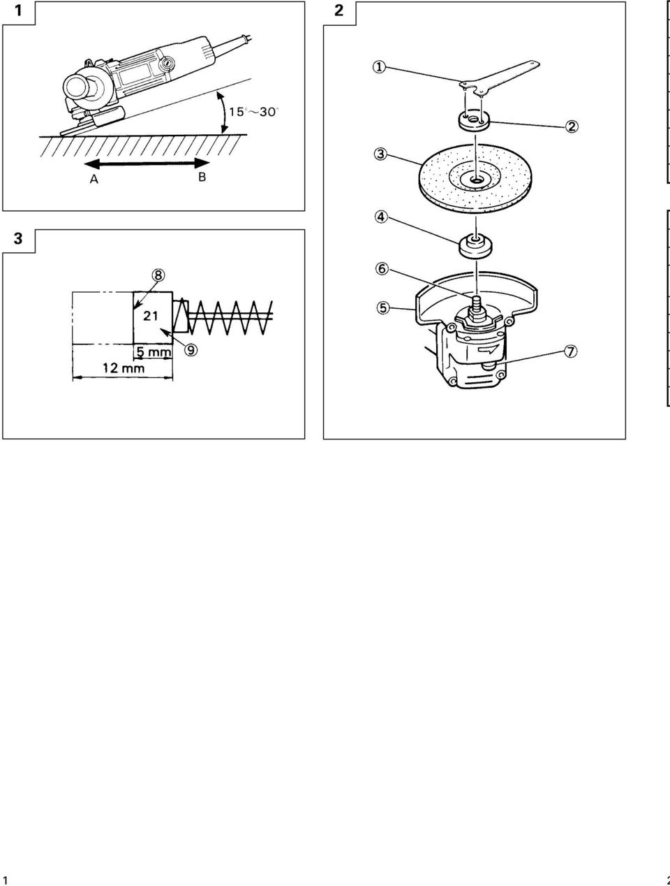
3 English Deutsch Français Italiano 1 Wrench Schlüssel Clef Chiave 2 Wheel nut Mutter für Schleifscheibe Ecrou de la meule Dado ad anello 3 Depressed center wheel Schleifscheibe Meule Mola 4 Wheel washer Unterlegscheibe Rondelle de la meule Rondella grover 5 Wheel guard Schutzhaube Couvre-meule Carter della mola 6 Spindle Spindel Arbre Asse 7 Lock pin Sperrstift Goupille de blocage Spina di bloccaggio 8 Wear limit Verschleißgrenze Limite d usure Límite di usura 9 No. of carbon brush Nr. der Kohlebürste No. du balai en carbone N. della spazzola di carbone Nederlands Español Português Ελληνικά 1 Sleutel Llave para tuercas Chave inglesa Κλειδί 2 Moer voor de schuurschijf Contratuerca molar Arruela de roda Παξιµάδι τροχού 3 Schuurschijf Muela de alisado Esmeril Χαµηλωµένος κεντρικά τροχός 4 Onderlegschijf Arandela molar Porca de roda Ροδέλλα τροχού 5 Beschermkap Cubierta protector de muela Proteção de roda Προφυλακτήρας τροχού 6 As Eje Eixo Άξονας 7 Blokkeerstift Pasador de cierre Pino de retenção Ασφαλιστικός πείρος 8 Slijtagegrens Límite de uso Limite de desgaste Όριο φθοράς 9 Nr. van de koolborstel No. de carbón de contacto Nº de escova de carvão Aρ. Kαρβουνακιού 2

4 English GENERAL OPERATIONAL PRECAUTIONS WARNING! When using electric tools, basic safety precautions should always be followed to reduce the risk of fire, electric shock and personal injury, including the following. Read all these instructions before operating this product and save these instructions. For safe operations: 1. Keep work area clean. Cluttered areas and benches invite injuries. 2. Consider work area environment. Do not expose power tools to rain. Do not use power tools in damp or wet locations. Keep work area well lit. Do not use power tools where there is risk to cause fire or explosion. 3. Guard against electric shock. Avoid body contact with earthed or grounded surfaces. (e.g. pipes, radiators, ranges, refrigerators). 4. Keep children away. Do not let visitors touch the tool or extension cord. All visitors should be kept away from work area. 5. Store idle tools. When not in use, tools should be stored in a dry, high or locked up place, out of reach of children. 6. Do not force the tool. It will do the job better and safer at the rate for which it was intended. 7. Use the right tool. Do not force small tools or attachments to do the job of a heavy duty tool. Do not use tools for purposes not intended; for example, do not use circular saw to cut tree limbs or logs. 8. Dress properly. Do not wear loose clothing or jewery, they can be caught in moving parts. Rubber gloves and non-skid footwear are recommended when working outdoors. Wear protecting hair covering to contain long hair. 9. Use eye protection. Also use face or dust mask if the cutting operation is dusty. 10. Connect dust extraction equipment. If devices are provided for the connection of dust extraction and collection facilities ensure these are connected and properly used. 11. Do not abuse the cord. Never carry the tool by the cord or yank it to disconnect it from the receptacle. Keep the cord away from heat, oil and sharp edges. 12. Secure work. Use clamps or a vise to hold the work. It is safer than using your hand and it frees both hands to operate tool. 13. Do not overreach. Keep proper footing and balance at all times. 14. Maintain tools with care. Keep cutting tools sharp and clean for better and safer performance. Follow instructions for lubrication and changing accessories. Inspect tool cords periodically and if damaged, have it repaired by authorized service center. Inspect extension cords periodically and replace, if damaged. Keep handles dry, clean, and free from oil and grease. 15. Disconnect tools. When not in use, before servicing, and when changing accessories such as blades, bits and cutters. 16. Remove adjusting keys and wrenches. Form the habit of checking to see that keys and adjusting wrenches are removed from the tool before turning it on. 17. Avoid unintentional starting. Do not carry a plugged-in tool with a finger on the switch. Ensure switch is off when plugging in. 18. Use outdoor extension leads. When tool is used outdoors, use only extension cords intended for outdoor use. 19. Stay alert. Watch what you are doing. Use common sense. Do not operate tool when you are tired. 20. Check damaged parts. Before further use of the tool, a guard or other part that is damaged should be carefully checked to determine that it will operate properly and perform its intended function. Check for alignment of moving parts, free running of moving parts, breakage of parts, mounting and any other conditions that may affect its operation. A guard or other part that is damaged should be properly repaired or replaced by an authorized service center unless otherwise indicated in this handling instructions. Have defective switches replaced by an authorized service center. Do not use the tool if the switch does not turn it on and off. 21. Warning The use of any accessory or attachment, other than those recommended in this handling instructions, may present a risk of personal injury. 22. Have your tool repaired by a qualified person. This electric tool is in accordance with the relevant safety requirements. Repairs should only be carried out by qualified persons using original spare parts. Otherwise this may result in considerable danger to the user. PRECAUTIONS ON USING DISC GRINDER 1. Never operate these power tools without Wheel Guards. 2. Use only depressed center wheels with a Safe Speed of at least as high as the No-Load RPM indicated on the power tool nameplate. 3. Always hold the body handle and side handle of the power tool firmly. Otherwise the counterforce produced may result in inaccurate and even dangerous operation. 4. Do not work near welding equipment. If you work near welding equipment, rotation may become unstable. 3

5 English SPECIFICATIONS Model G10SG G12SG Voltage (by areas)* (110V, 115V, 220V, 230V, 240V) Power Input* 670 W No-load speed* 12000/min 10000/min Wheel outer dia. hole dia mm mm peripheral speed 4300m/min 4800m/min Weight (only main body) 1.3 kg *Be sure to check the nameplate on product as it is subject to change by areas. STANDARD ACCESSORIES (1) Depressed center wheel... 1 (2) Wrench... 1 (3) Side handle... 1 Standard accessories are subject to change without notice. APPLICATIONS Removal of casting fin and finishing of various types of steel, bronze and aluminum materials and castings. Grinding of welded sections or sections cut by means of a cutting torch. Grinding of synthetic resins, slate, brick, marble, etc. PRIOR TO OPERATION 1. Power source Ensure that the power source to be utilized conforms to the power requirements specified on the product nameplate. 2. Power switch Ensure that the power switch is in the OFF position. If the plug is connected to a receptacle while the power switch is in the ON position, the power tool will start operating immediately, which could cause a serious accident. 3. Extension cord When the work area is removed from the power source, use an extension cord of sufficient thickness and rated capacity. The extension cord should be kept as short as practicable. 4. Fitting and adjusting the wheel guard The wheel guard is a protective device to prevent injury should the depressed center wheel shatter during operation. Ensure that the guard is poperly fitted and fastened before commencing grinding operation. By slightly loosening the setting screw, the wheel guard can be turned and set at any desired angle for maximum operational effectiveness. Ensure that the setting screw is thoroughly tightened after adjusting the wheel guard. 5. Ensure that the depressed center wheel to be utilized is the correct type and free of cracks or surface defects. Also ensure that the depressed center wheel is poperly mounted and the wheel nut is securely tightened. Refer to the section on Depressed Center Wheel Assembly Conducting a trial run Before commencing grinding operation, the machine should be given a trial run in a safe area to ensure that it is properly assembled and that the depressed center wheel is free from obvious defects. Recommended trial run durations are as follows: After replacing depressed center wheel... 3 minutes or more Prior to starting routine work... 1 minutes or more 7. Confirm the lock pin. Confirm that the lock pin is disengaged by pushing lock pin two or three times before switching the power tool on (See Fig. 2). 8. Fixing the side handle. Screw the side handle into the gear cover. PRACTICAL GRINDER APPLICATION 1. Pressure To prolong the life of the machine and ensure a first class finish, it is important that the machine should not be overloaded by applying too much pressure. In most applications, the weight of the machine alone is sufficient for effective grinding. Too much pressure will result in reduced rotational speed, inferior surface finish, and overloading which could reduce the life of the machine. 2. Grinding angle Do not apply the entire surface of the depressed center wheel to the material to be ground. As shown in Fig. 1, the machine should be held at an angle of so that the external edge of the depressed center wheel contacts the material at an optimum angle. 3. To prevent a new depressed center wheel from digging into the workpiece, initial grinding should be performed by drawing the grinder across the workpiece toward the operator (Fig. 1 direction B). Once the leading edge of the depressed center wheel is properly abraded, grinding may be conducted in either direction. 4. Precautions immediately after finishing operation After switching off the machine, do not put it down until the depressed center wheel has come to a complete stop. Apart from avoiding serious accidents, this precaution will reduce the amount of dust and swarf sucked into the machine.

6 English CAUTION When the machine is not use, the power source should be disconnected. ASSEMBLING AND DISASSEMBLING THE DEPRESSED CENTER WHEEL (Fig. 2) CAUTION: Be sure to switch OFF and disconnect the attachment plug from the receptacle to avoid a serious accident. 1. Assembling (Fig. 2) (1) Turn the equipment upsidedown so that the spindle will be facing up. (2) Mount the wheel washer onto the spindle. (3) Fit the protuberance of the depressed center wheel onto the wheel washer. (4) Screw from above the wheel nut onto the spindle. (5) As shown in Fig. 2, push in the lock pin to prevent rotation of the spindle. Then, secure the depressed center wheel by tightening the wheel nut with the wrench. 2. Disassembling Follow the above procedures in reverse. CAUTIONS Comfirm that the depressed center wheel is mounted firmly. Confirm that the lock pin is disengaged by pushing lock pin two or three times before switching the power tool on. MAINTENANCE AND INSPECTION 1. Inspecting the depressed center wheel Ensure that the depressed center wheel is free of cracks and surface defects. 2. Inspecting the mounting screws: Regularly inspect all mounting screws and ensure that they are properly tightened. Should any of the screws be loose, retighten them immediately. Failure to do so could result in serious hazard. 3. Inspecting the carbon brushes (Fig. 3) The motor employs carbon brushes which are consumable parts. Since an excessively worn carbon brush can result in motor trouble, replace the carbon brush with a new one having the same carbon brush No. shown in the figure when it becomes worn to or near the wear limit. In addition, always keep carbon brushes clean and ensure that they slide freely within the brush holders. 4. Replacing carbon brushes Disassemble the brush cap with a screwdriver. The carbon brush can then be easily removed. 5. Maintenance of the motor The motor unit winding is the very heart of the power tool. Exercise due care to ensure the winding does not become damaged and/or wet with oil or water. 6. Service parts list A: Item No. B: Code No. C: No. Used D: Remarks CAUTION Repair, modification and inspection of Hitachi Power Tools must be carried out by an Hitachi Authorized Service Center. This Parts List will be helpful if presented with the tool to the Hitachi Authorized Service Center when requesting repair or other maintenance. In the operation and maintenance of power tools, the safety regulations and standards prescribed in each country must be observed. MODIFICATIONS Hitachi Power Tools are constantly being improved and modified to incorporate the latest technological advancements. Accordingly, some parts (i.e. code numbers and/or design) may be changed without prior notice. NOTE Due to HITACHI s continuing program of research and development, the specifications herein are subject to change without prior notice. IMPORTANT Correct connection of the plug The wires of the main lead are coloured in accordance with the following code: Blue: -Neutral Brown: -Live As the colours of the wires in the main lead of this tool may not correspond with the coloured markings identifying the terminals in your plug proceed as follows: The wire coloured blue must be connected to the terminal marked with the letter N or coloured black. The wire coloured brown must be connected to the terminal marked with the letter L or coloured red. Neither core must be connected to the earth terminal. NOTE This requirement is provided according to BRITISH STANDARD 2769: Therefore, the letter code and colour code may not be applicable to other markets except The United Kingdom. Information concerning airborne noise and vibration The measured values were determined according to EN The typical A-weighted sound pressure level: 87 db (A). The typical A-weighied sound power level: 100 db (A). Wear ear protection. The typical weighted root mean square acceleration value: 4.0 m/s 2. 5
 Screw from above the wheel nut onto the spindle. (5) As shown in Fig. 2, push in the lock pin to prevent rotation of the spindle.")
7 Deutsch ALLGEMEINE VORSICHTSMASSNAHMEN WARNUNG! Bei der Verwendung von Elektrowerkzeugen müssen immer die grundlegenden Vorsichtsmaßnahmen befolgt werden, um das Risiko von Feuer, elektrischem Schlag und persönlicher Verletzung und den nachfolgenden Punkten zu vermeiden. Lesen Sie diese Anweisungen völlig, bevor Sie dieses Erzeugnis verwenden, und bewahren Sie diese Anweisungen auf. Für sicheren Betrieb: 1. Der Arbeitsplatz sollte sauber gehalten werden. Unaufgeräumte Arbeitsplätze und Werkbänke erhöhen die Unfallgefahr. 2. Die Betriebsbedingungen beachten. Elektrowerkzeuge sollten nicht dem Regen ausgesetzt werden. Ebenfalls sollten Sie nicht an feuchten oder nassen Plätzen gebraucht werden. Der Arbeitsplatz sollte gut beleuchtet sein. Verwenden Sie Elektrowerkzeuge nicht an Orten, an denen die Gefahr von Feuer oder Explosion besteht. 3. Schutzmaß nahmen gegen elektrische Schläge treffen. Darauf achten, daß das Gehäuse nicht in Kontakt mit geerdeten Flachen kommt, z. (z.b. Rohre, Radiatoren, Elektroherde, Kühlschränke). 4. Kinder sollten vom Gerät ferngehalten werden. Vermeiden, daß andere Personen mit dem Werkzeung oder Verlängerungskabel in Kontakt kommen. 5. Nicht benutzte Werkzeuge sollten sicher aufbewahrt werden. Sie sollten an einem trockenen und verschließbaren Ort aufbewahrt werden, damit Kinder sie nicht in die Hände bekommen. 6. Werkzeuge sollten nicht mit übermäßiger Gewalt verwendet werden. Ihre Leistung ist besser und sicherer, wenn sie mit der vorgeschriebenen Geschwindigkeit verwendet werden. 7. Nur die korrekten Werkzeuge verwenden. Niemals ein kleineres Werkzeug oder Zusatzgerat für Arbeiten verwenden, die Hochleistungsgerate erfordern. Nur Werkzeuge verwenden, die dem Verwendungszweck entsprechen, d.h. niemals eine Kreissäge zum Sägen von Ästen oder Baumstämmen verwenden. 8. Die richtige Kleidung tragen. Keine lose Kleidung oder Schmuck tragen, da sich lose Kleidungsstücke in den bewegenden Teilen verfangen kònnen. Bei Arbeiten im Freien sollten Gummihandschuhe und rutschfeste Schuhe getragen werden. 9. Es sollte eine Sicherheitsbrille getragen werden. Bei Arbeiten mit Staubentwicklung sollte eine Gesichtsoder Staubmaske getragen werden. 10. Schließen Sie eine Staubabsaugvorrichtung an. Wenn Vorrichtungen für den Anschluß von Staubabsaug- und -sammelvorrichtungen vorhanden sind, so stellen Sie sicher, daß diese angeschlossen sind und richtig verwendet werden. 11. Niemals das Kabel mißbrauchen. Ein Werkzeug niemals am Kabel tragen oder bei Abtrennung von der Steckdose das Kabel harausreißen. Das Kabel sollte gegen Hitze, Öl und scharfe Kanten geschützt werden Den Arbeitsplatz gut absichern. Zwingen oder einen Schraubstock zur Befestigung des Werkstücks verwenden. Das ist sicherer als die Benutzung der Hände und macht beide Hände zur Bedienung des Werkzeugs frei. 13. Sich niemals weit überbeugen. Immer einen festen Stand und ein sicheres Gleichgewicht bewahren. 14. Die Werkzeuge sollten sorgfältig behandelt werden. Für einen einwandfreien und sicheren Betrieb sollten sie stets scharf sein und saubergehalten werden. Die Anleitungen für schmierung und Austausch des Zuehörs unbedingt einhalten. Die Kabel der Geräte regelmäßig überprüfen und bei Beschädigung durch eine autorisierte Kundendienststelle reparieren lassen. Ebenfalls die Verlägerungskabel regelmäßig überprüfen und bei Beschadigung auswechseln. Die Handgriffe sollten stets trocken und sauber sein, sowie keine Ol- oder Schmierfett stellen aufweisen. 15. Werkzeuge vom Netz trennen, wenn sie nicht benutzt werden, vor Wartungsarbeiten und beim Austausch von Zubehörteilen wie z.b. Blätter, Bohrer und Messer. 16. Alle Stellkeile und Schraubenschlüssel entfernen. Vor Einschaltung des Gerätes darauf achten, daß alle Stellkeile und Schraubenschlüssel entfernt worden sind. 17. Ein unbeabsichtigtes Einschalten sollte vermieden werden. Niemals ein angeschlossenes Werkzeug mit dem Finger am Schalter tragen. Vor Anschluß überprüfen, ob das Gerät ausgeschaltet ist. 18. Im Freien ein Verlängerungskabel verwenden. Nur ein Verlängerungskabel verwenden, das für die Verwendung im Freien markiert ist. 19. Den Arbeitsvorgang immer unter Kontrolle haben. Das Gerät niemals in einem abgespannten Zustand verwenden. 20. Beschädigte Teile überprüfen. Vor Benutzung des Werkzeugs sollten beschädigte Teile oder Schutzvorrichtungen sorgfältig überprüft werden, um festzustellen, ob sie einwandfrei funktionieren und die vorgesehene Funktion erfüllen, Ausrichtung, Verbindungen sowie Anbringung sich bewegender Teile überprüfen. Ebenfalls uberprufen, ob Teile gebrochen sind. Teile oder Schutzvorrichtungen, die beschädigt sind, sollten, wenn in dieser Bedienungsanleitung nichts anderes erwähnt ist, durch eine autorisierte Kundendienststelle ausge wechselt oder repariert werden. Dasselbe gilt für defekte Schalter. Wenn sich das Werkzeug nicht mit dem Schalter einoder ausschalten läßt, sollte das Werkzeug nicht verwendet werden. 21. Warnung Die Verwendung von anderem Zubehör oder anderen Zusätzen als in dieser Bedienungsanleitung empfohlen kann das Risiko einer Körperverletzung einschließen. 22. Lassen Sie Ihr Werkzeug durch qualifiziertes Personal reparieren. Dieses Elektrowerkzeug entspricht den zutreffenden Sicherheitsanforderungen. Reparaturen sollten nur von qualifiziertem Personal unter Verwendung von Originalersatzteilen durchgeführt werden, da sonst beträchtliche Gefahr für den Benutzer auftreten kann.

8 Deutsch VORSICHTSMASSNAHMEN BEI DER BENUTZUNG DES WINKELSCHLEIFERS 1. Diese Werkzeuge nie ohne Schutzhaube benutzen. 2. Nur Schleifscheiben mit einer Sicherheitsgeschwindigkeit benutzen, die mindestens ebenso hoch ist wie die Leerlaufdrehzahl, die auf dem Typenschild des Werkzeugs angegeben ist. 3. Immer den Körper-Handgriff und den Seiten- Handgriff des Elektrowerkzeugs festhalten, weil sonst die entstehende Gegenkraft zu einem ungenauen und sogar gefährlichen Arbeiten führen kann. 4. Nicht in der Nähe von Schweißgeräten arbeiten. Wenn in der Nähe von Schweißgeräten gearbeitet wird, kann die Drehung unregelmäßig, werden. TECHNISCHE DATEN Modell G10SG G12SG Spannung (je nach Gebiet)* (110V, 115V, 220V, 230V, 240V) Leistungsaufnahme* 670 W Leerlaufdrehzahl* 12000/min 10000/min Schleifscheibe Außendurchmesser Innendurchmesser mm mm Umfangsgeschwindigkeit 4300m/min 4800m/min Gewicht (Gerät selbst) 1,3 kg * Vergessen Sie nicht, die Produktangaben auf dem Typenschild zu überprüfen, da sich diese je nach Verkaufsgebiet ändern. STANDARDZUBEHÖR (1) Schleifscheibe... 1 (2) Schlüssel... 1 (3) Handgriff... 1 Das Standardzubehör kann ohne vorherige Bekanntmachung jederzeit geändert werden. ANWENDUNGSGEBIETE Entfernung von Gußgrat und Endbearbeitung verschiedener Stahlqualitäten, Bronze-und Aluminiummaterialien und Gußteile. Schleifen von geschweißten Stücken oder von durch Brennschneiden hergestellten Abschnitten. Schleifen von Kunstharz, Schiefer, Ziegelstein, Marmor, usw. VOR INBETRIEBNAHME 1. Netzspannung Prüfen, daß die zu verwendende Netzspannung der Angabe auf dem Typenschild entspricht. 2. Netzschalter Prüfen, daß der Netzschalter auf AUS steht. Wenn der Stecker an das Netz angeschlossen wird, während der Schalter auf EIN steht, beginnt das Werkzeung sofort zu laufen, was gefährlich ist. 3. Verlängerungskabel Wenn der Arbeitsbereich nicht in der Nähe des Netzanschlusses liegt, ist ein Verlängerungskabel ausreichenden Querschnitts und ausreichender Nennleistung zu verwenden. Das Verlängerungskabel sollte so kurz wie möglich gehalten werden. 4. Anbringen und Einstellen der Schutzhaube Die Schutzhaube ist eine Schutzvorrichtung, durch die Schaden verhindert werden soll, wenn die Schleifscheibe während des Betriebs zerbrechen sollte. Es ist darauf zu achten, daß die Haube ordnungsgemäß angebracht und befestigt ist, ehe mit der Schleifarbeit begonnen wird. Durch geringfügiges Lockern der Arretierschraube kann die Schutzhaube gedreht und in jedem gewünschten Winkel zur Erzielung maximaler Leistung eingestellt werden. Es ist sicherzustellen, daß die Arretierschraube nach dem Einstellen der Schutzhaube ordnungsgemäß angezogen wird. 5. Es ist weiter darauf zu achten, daß die zu verwendende Schleifscheibe die richtige Ausführung und ohne Risse und Oberflächenfehler ist. Es ist auch darauf zu achten, daß die Schleifscheibe richtig montiert und die Mutter der Schleifscheibe fest angezogen ist. Siehe Abschnitt Anbringen der Schleifscheibe. 6. Durchführung eines Probelaufs Ehe mit der Schleifarbeit begonnen wird, sollte man mit der Maschine einen Probelauf an einer sicheren Stelle durchführen, um sich zu überzeugen, daß sie richtig zusammengesetzt und die Schleifscheibe ohne sichtbare Fehler ist. Die empfohlene Dauer der Probeläufe beträgt: Nach dem Austausch der Schleifscheibe... 3 Minuten oder mehr. Vor Beginn der Routinearbeit... 1 Minute oder mehr. 7. Überprüfen des Sperrstiftes: Es ist zu überprüfen, ob der Sperrstift gelöst ist, indem zwei- oder dreimal vor Einschalten des Gerätes auf den Sperrstift gedrückt wird. (s. Abb. 2) 8. Anbringen des Handgriffs Den Handgriff in den Getriebedeckel einschrauben. 7

9 Deutsch PRAKTISCHE SCHLEIFARBEIT 1. Druck Zur Verlängerung der Lebensdauer Maschine und für erstklassige Arbeit ist es wichtig, daß die Maschine nicht durch zu starken Druck überbelastet wird. Bei den meisten Anwendungen reicht das Gewicht der Maschine für effektives Schleifen aus. Zu starker Druck führt zu verminderter Drehzahl, unbefriedigendem Oberflächenaussehen und einer Überbelastung, die die Lebensdauer der Maschine vermindem könnte. 2. Schleifwinkel Nicht die gesamte Fläche der Schleifscheibe auf das zu schleifende Material auflegen. Die Maschine sollte, wie in Abb. 1 dargestellt ist, in einem Winkel von gehalten werden, so dadie Außenkante der Schleifscheibe das Werkstück in einem optimalen Winkel berührt. 3. Damit sich eine neue Schleifscheibe nicht in das Werkstück hineingräbt, sollte zu Anfang die Schleifarbeit so durchgeführt werden, daß der Winkelschleifer über das Werkstück zum Bedienungsmann gezogen wird (Abb. 1 Richtung B). Wenn die Vorderkante der Schleifscheibe entsprechend abgeschliffen ist, kann das Schleifen in beiden Richtungen durchgeführt werden. 4. Vorsichtsmaßnahmen unmittelbar nach Beendigung der Arbeit Nach dem Ausschalten darf die Maschine erst abgelegt werden, wenn die Schleifscheibe völlig zum Stillstand gekommen ist. Abgesehen vom Vermeiden ernsthafter Unfälle wird durch diese Vorsichtsma nahme vermieden, daß Staub und Späne in die Maschine gesaugt werden. ACHTUNG Wenn die Maschine nicht benutzt wird, sollte der Netzstecker gezogen werden. ANBRINGEN UND ABNEHMEN DER SCHLEIFSCHEIBE (Abb. 2) VORSICHT: Immer den Betriebsschalter auf Aus stellen und den Netzstecker aus der Steckdose ziehen, um Unfälle zu vermeiden. 1. Anbringen (Abb. 2) (1) Das Gerät umdrehen, so daß die Spindelseite nach oben weist. (2) Die Unterlegscheibe auf die Spindel setzen. (3) Den Vorsprung der Schleifscheibe auf die Unterlegscheibe setzen. (4) Von oben die Mutter für die Schleifscheibe auf die Spindel schrauben. (5) Wie in Abb. 2 gezeigt den Verriegelungsstift eindrücken, um die Drehung der Spindel zu verhüten. Dann die Schleifscheibe durch Festziehen der Mutter für die Schleifscheibe mit dem Schlüssel befestigen. 2. Abnehmen Beim Abnehmen wird in umgekehrter Reihenfolge vorgegangen. VORSICHT Prüfen, ob die Schleifscheibe fest angezogen ist. Es ist zu überprüfen, ob der Verriegelungsstift freigegeben ist, indem zwei- oder dreimal vor Einschalten des Gerätes auf den Verriegelungsstift gedrückt wird. WARTUNG UND INSPEKTION 1. Überprüfung der Schleifscheibe Es ist darauf zu achten, daß die Schleifscheibe ohne Risse und Fehler an der Oberfläche ist. 2. Inspektion der Befestigungsschrauben: Alle Befestigungsschrauben werden regelmäßig inspiziert und geprüft, ob sie gut angezogen sind. Wenn sich eine der Schrauben lockert, muß sie sofort wieder angezogen werden. Geschieht das nicht, kann das zu erheblichen Gefahren führen. 3. Inspektion der Kohlebürsten (Abb. 3) Im Motor sind Kohlebürsten verwendet, die Verbrauchsteile sind. Übermaßig abgenutzte Kohlenbürsten führen zu Motor, problemen. Deshalb wird eine Kohlebürste durch eine neue ersetzt, die dieselbe Nummer trägt wie auf der Abbildung gezeigt, wenn sie teilweise oder ganz verbraucht ist. Darüber hinaus müssen die Kohlebürsten immer sauber gehalten werden und müssen sich in der Halterung frei bewegen können. 4. Austausch einer Kohlebürste Der Bürstendeckel wird mit einem Steckschlüssel abmontiert. Dann kann die Kohlebürste leicht entfernt werden. 5. Wartung des Motors Die Motorwicklung ist das Herz des Elektrowerkzeugs. Daher ist besonders sorgfältig darauf zu achten, daß die Wicklung nicht beschädigt wird und/oder mit Öl oder Wasser in BerUhrung kommt. 6. Liste der Wartungsteile A: Punkt Nr. B: Code Nr. C: Verwendete Anzahl D: Bemerkungen ACHTUNG Reparatur, Modifikation und Inspektion von Hitachi- Elektrowerkzeugen müssen durch ein autorisiertes Hitachi-Kundendienstzentrum durchgeführt werden. Diese Teileliste ist hilfreich, wenn sie dem autorisierten Hitachi-Kundendienstzentrum zusammen mit dem Werkzeug für Reparatur oder Wartung ausgehändigt wird. Bei Betrieb und Wartung von Elektrowerkzeugen müssen die Sicherheitsvorschriften und Normen beachtet werden. MODIFIKATIONEN Hitachi-Elektrowerkzeuge werden fortwährend verbessert und modifiziert, um die neuesten technischen Fortschritte einzubauen. Dementsprechend ist es möglich, daß einige Teile (z.b. Codenummern bzw. Entwurf) ohne vorherige Benachrichtigung geändert werden. ANMERKUNG Aufgrund des ständigen Forschungs-und Entwicklungsprogramms von HITACHI sind Änderungen der hierin gemachten technischen Angaben nicht ausgeschlossen. 8

10 Deutsch Information über Betriebslärm und Vibration Die Meßwerte wurden entsprechend EN50144 bestimmt. Der typische A-gewichtete Schalldruckt ist 87 db (A). Der typische A-gewichtete Schalleistungspegel ist 100 db (A). Bei der Arbeit immer einen Ohrenschutz tragen. Der typische gewogene quadratische Mittelwert für die Beschleunigung ist 4,0 m/s 2. 9

11 Français PRECAUTIONS GENERALES DE TRAVAIL ATTENTION! Lors de l utilisation d un outillage électrique, les précautions de base doivent être respectées de manière à réduire les risques d incendie, de secousse électrique et de blessure corporelle, y compris les précautions suivantes. Lire ces instructions avant d utiliser le produit et conserver ces instructions pour référence. Pour assurer un fonctionnement sûr: 1. Maintenir l aire de travail propre. Des ateliers ou des établis en désordre risquent de provoquer des accidents. 2. Tenir compte de l environnement de l aire de tra vail. Ne pas exposer les outils électriques à la pluie. Ne pas les utiliser dans des endroits humides. Travailler dans un endroit bien éclairé. Ne pas utiliser d outillage électrique s il existe un risque d incendie ou d explosion. 3. Protection contre une décharge électrique. Eviter tout contact corporel avec des surfaces de mise à la terre telles que les tuyaux, radiateurs, cuisinières et réfrigérateurs. 4. Tenir les enfants éloignés. Ne pas laisser les visiteurs toucher l outil ou son cordon d alimentation. Il est préférable de tenir les visiteurs à l écart de l aire de travail. 5. Ranger les outils non utilisés. Quand on ne les utilise pas, il est recommandé de ranger les outils dans un endroit sec, verrouillé ou hors de portée des enfants. 6. Ne pas forcer l outil. Il fonctionnera mieux et plus sûrement à la vitesse pour laquelle il a été con cu. 7. Utiliser l outil approprié. Ne pas essayer de faire avec un petit outil le travail prevu pour un outil plus important. Toujours utiliser l outil adéquat; par exemple, ne pas se servir d une scie circulaire pour couper des branches d arbres ou des billots de bois. 8. Porter des vêtements appropriés. Ne pas mettre de vêtements flottants ou de bijoux qui risquent d être pris dans les pièces mobiles. Si l on travaille à l extérieur, il est recommandé de porter des gants de caoutchouc et des chaussures à semelles antidérapantes. Veiller à s attacher les cheveux ou à mettre un bonnet si on a les cheveux longs. 9. Porter des lunettes protectrices. Mettre un masque si l opération de coupe crée de la poussière. 10. Relier l équipement d extraction de poussière. Si des dispositifs sont prévus pour le raccordement d installations d extraction et de collection de poussière, s assurer qu ils sont correctement raccordés et utilisés. 11. Prendre soin du fil. Ne jamais transporter l outil en le tenant par le fil et ne pas le débrancher en tirant sur le fil d un coup sec. Tenir le fil à l abri de la chaleur, l éloigner de l huile ou de bords tranchants. 12. Fixer fermement la piêce à travailler. Utiliser des agrafes ou un étau pour la maintenir, C est plus sûr que d utiliser ses mains et cela les libêre pour faire fonctionner l outil. 13. Ne pas présumer de ses forces. Essayer de garder son équilibre en toute circonstance. 14. Entretenir les outils avec soin. Les conserver bien aiguisés et les nettoyer afin d en obtenir les meilleures performances et de pouvoir les utiliser sans danger. Suivre les instructions pour le graissage et le changement des accessoires. Vérifier régulièrement les fils et cordons et s ils sont endommagés, les faire réparer par une personne compétente. Vérifier régulièrement les rallonges et les remplacer si elles sont endommagées. Veiller à ce que les poignées soient toujours sèches et propres, sans huile ni graisse. 15. Debrancher les outils lorsqu on ne les utilise pas, avant toute opération d entretien et lors du changement d accessoire; comme par exemple quand on change les lames, les forets, le fraises, etc. 16. Retirer les clés de réglage. Prendre l habitude de toujours vérifier que les clés de réglage sont bien retirées de l appareil avant de le mettre en marche. 17. Eviter toute mise en marche accidentelle. Ne pas transporter l outil branché avec un doigt sur l interrupteur. S assurer que l interrupteur est sur la position d arrêt quand on branche l outil. 18. Utilisation de rallonges à l extérieur. Quand on utilise l outil à l extérieur, ne se servir que des rallonges prévues pour l extérieur et portant une marque distinctive. 19. Soyez vigilant. Regardez bien ce que vous faites. Faites appel à votre bon sens. N utilisez pas l outil quand vous êtes fatigué. 20. Vérifier les pièces endommagées. Avant d utiliser davantage l outil, vérifier attentivement toute pièce endommagée afin de déterminer si l outil peut fonctionner correctement et effectuer le travail pour lequel il est prévu. Vérifier l alignement et la flexion des piêces mobiles, la cassure des pièces, le montage et toute autre condition risquant d affecter le bon fonctionnement de l outil. Un protecteur ou toute autre pièce endommagée devra être correctement réparé ou remplacé par un service d entretien autorisé, sauf autre indication dans ce mode d emploi. Faire remplacer les interrupteurs défectueux par un service d entretien autorisé. Ne pas utiliser l outil si l interrupteur ne permet pas de le mettre en marche ou de l arrêter. 21. Précaution L utilisation d un accessoire ou dispositif annexe autre que ceux conseillés dans ce mode d emploi peut entraîner un risque de blessure corporelle. 22. Confier la réparation d un outil à un technicien qualifié. Cet outil électrique a été conçu conformément aux règles de sécurité en usage. Les réparations doivent être effectuées par du personnel qualifié utilisant des pièces d origine. Dans le cas contraire, l utilisateur s expose à des risques graves. 10

12 Français PRECAUTIONS D UTILISATION DE LA MEULEUSE 1. Ne jamais faire fonctionner ces outils sans couvremeules. 2. N utiliser les meules qu avec la vitesse de sécurit au moins aussi élevée que la vitesse horscharge indiquée sur la plaque signalétique de l outil. 3. Maintenir toujours fermement la poignée principale et la poignée latérale de la machine. Dans le cas contraire, la force de recul peut amoindrir la précision de travail et présenter ainsi quelque danger. 4. Ne pas travailler près d équipements de soudure. La rotation peut devenir instable si on travaille près d équipements de soudure. SPECIFICATIONS Modèle G10SG G12SG Tension (par zone)* (110V, 115V, 220V, 230V, 240V) Puissance* 670 W Vitesse hors charge* 12000/min 10000/min Meule diamètre extérieur diamètre intérieur mm mm vitesse périphérique 4300 m/min 4800 m/min Poids (unité principale uniquement) 1,3 kg * Assurez-vous de vérifier la plaque signalétique sur le produit, car elle peut changer suivant les zones ACCESSOIRES STANDARD (1) Meule... 1 (2) Clef... 1 (3) Poignée latérale... 1 Les accessoires standard sont sujets àchangement sans préavis. APPLICATIONS Enlèvement des bavures de moulage et finition de différentes sortes de matériaux en acier, bronze ou aluminium et de moulages. Meulage de sections soudées ou de sections coupées par soudage. Meulage de résines synthétiques, d ardoises, de briques, de marbre, etc. AVANT LA MISE EN MARCHE 1. Source de puissance S assurer que la source de puissance àutiliser correspond àla puissance indiquée sur la plaque signalétique du produit. 2. Interrupteur de puissance S assurer que l interrupteur de puissance est en position ARRET. Si la fiche est branchée alors que l interrupteur est sur MARCHE, l outil démarre immédiatement et peut provoquer un grave accident. 3. Fil de rallonge Lorsque la zone de travail est éloignée de la source de puissance, utiliser un fil de rallonge d une épaisseur suffisante et d une capaciténominale suffisante. Le fil de rallonge doit être aussi court que possible. 4. Fixation et réglage du couvre-meule Le couvre-meule est un dipositif de protection pour éviter une blessure au cas oùla meule se briserait lors du fonctionnement. S assurer qu il est correctement placéet fixé avant de commencer meuler et régler l angle souhaité du modèle. S assurer que l écrou de réglage est resserré à fond après le réglage du couvre-meule. 5. S assurer que la meule utilisée est le bon modèle, et qu elle est dépourvue de fêlures et de défauts de surface. Vérifier aussi que la meule est correctement montée et que l écrou de la meule est bloqué Consulter la section Montage de la meule. 6. Effectuer un essai Avant de commencer une opération de meulage, la machine doit être essayée dans une zone sûre pour vérifier qu elle est correctement assemblée et que la meule est dépourvue de défauts évidents. Les durées recommandées de ces essais sont les suivantes: Après remplacement de la meule... 3 minutes minimum Avant de commencer un travail de routine... 1 minute minimum 7. Vérifier la goupille de blocage Vérifier que la goupille de blocage est dégagée en poussant la goupille deux ou trois fois avant de brancher l outil. (Voir Fig. 2) 8. Mise en place de la poignée latérale Visser la poignée latérale dans le couvercle d engrenage. FONCTIONNEMENT 1. Pression Pour prolonger la vie de la machine et réaliser un fini de première qualité, il est important de ne pas surcharger la machine en exerc ant une pression trop grande. Dans la plupart des applications, le poids de la machine seule suffit pour un bon meulage. Une trop grande pression peut entraíner une réduction de la vitesse de rotation, un moins bon fini de surface et une surcharge qui réduirait la durée de vie de la machine. 11

13 Français 2. Angle de meulage Ne pas appliquer la surface totale de la meule au matériau à meuler. Suivant la Fig. 1, la machine doit être tenue à un angle de de manière à ce que le bord extérieur de la meule soit en contact avec la pièce à meuler à un angle optimal. 3. Pour éviter qu une nouvelle meule ne creuse la pièce à meuler, le meulage initial doit se faire en tirant la machine vers l opérateur sur la pièce (Fig. 1 direction B). Une fois que le bord d attaque de la meule est correctement abrasé, on peut meuler dans l une ou l autre direction. 4. Précautions à prendre aussitôt le meulage terminé Après avoir arrêtéla machine, ne pas la poser avant l arrêt complet de la meule. Cette précaution évitera non seulement tout accident grave, mais réduira aussi la quantitde poussière et de copeaux de métal aspirée par la machine. ATTENTION Lorsque la machine n est pas utilisée, elle doit être débranchée. MONTAGE ET DEMONTAGE DE LA MEULE (Fig. 2) ATTENTION: S assurer de mettre l appareil hors tension et de déconnecter la prise du secteur pour éviter des problèmes. 1. Montage (Fig. 2) (1) Retourner l équipement de fac on à ce que l arbre soit dirigé vers le haut. (2) Monter la rondelle de la meule sur l arbre. (3) Faire correspondre la protubérance de la meule sur la rondelle de la meule. (4) Visser par le dessus l écrou de la meule sur l arbre. (5) Comme montré dans la Fig. 2, pousser la tige de verrouillage pour éviter que l arbre ne tourne. Fixer ensuite la meule en serrant l ecrou de meule avec une clé. 2. Démontage Même opération en sens inverse. ATTENTION Vous assurer que la meule est fermement montée. Vérifier que la tige de verrouillage est libérée en appuyant deux ou trois sur la tige de verrouillage avant de mettre l outil en marche. ENTRETIEN ET CONTROLE 1. Contrôle de la meule Vérifier que la meule est dépourvue de fêlures et de défauts de surface. Balai en carbone peut se retirer facilement. 2. Contrôle des vis de montage Vérifier régulièrement les vis de montage et s assurer qu elles sont correctement serrées. Resserrer immédiatement toute vis desserrée. Sinon, il y a danger sérieux. 3. Contrôle des balais en carbone (Fig. 3) Le moteur utilise des balais en carbone qui sont des pièces qui s usent. Comme un balai en carbone trop usé peut détériorer le moteur, le remplacer par un nouveau du même No. que celui montré à la figure quand il est usé ou à la limite d usure. En outre, toujours tenir les balais propres et veiller à ce qu ils coulissent librement dans les supports. 4. Remplacement d un balai en carbone Démonter le capuchon du balai avec un tournevis à petite tête. Le balai en carbone peut se retirer facilement. 5. Entretien du moteur Le bobinage de l ensemble moteur est le coeur même de l outil électro-portatif. Veiller soigneusement à ce que ce bobinage ne soit pas endommagé et/ou mouillé par de l huile ou de l eau. 6. Liste des pièces de rechange A: No. élément B: No. code C: No. utilisé D: Remarques ATTENTION Les réparations, modifications et inspections des outils électriques Hitachi doivent être confiées à un service après-vente Hitachi agréé. Il sera utile de présenter cette liste de pièces au service après-vente Hitachi agréé lorsqu on apporte un outil nécessitant des réparations ou tout autre entretien. Lors de l utilisation et de l entretien d un outil électrique, respecter les règlements et les normes de sécurité en vigueur dans le pays en question. MODIFICATIONS Les outils électriques Hitachi sont constamment améliorés et modifiés afin d incorporer les tous derniers progrès technologiques. En conséquence, il est possible que certaines pièces (c.-à-d. no. de code et/ou dessin) soient modifiées sans avis préalable. NOTE Par suite du programme permanent de recherche et de développement HITACHI, ces spécifications peuvent faire l objet de modifications sans avis préalable. Au sujet du bruit et des vibrations Les valeurs mesurées ont été déterminées en fonction de la norme EN Le niveau de pression acoustique pondéré A type est de 87 db (A). Le niveau de puissance sonore pondéré A type est de 100 db (A). Porter un casque de protection. Valeur d accélération moyenne quadratique pondérée type: 4,0 m/s 2. 12
.")
14 Italiano PRECAUZIONI GENERALI ATTENZIONE! Quando si usano elettroutensili, bisogna sempre seguire le precauzioni basilari di sicurezza per ridurre il rischio di incendi, scosse elettriche e lesioni alle persone, tra cui quanto segue. Leggere tutte queste istruzioni prima di usare questo prodotto e conservare le istruzioni. Per un funzionamento sicuro: 1. Mantenere sempre pulita l area dove si lavora. Un area di lavoro sempre pulita aiuta ad evitare incidenti. 2. Tenere nella dovuta considerazione le condizioni dell ambiente di lavoro. Non esporre gli elettroutensili alla pioggia. Non usare gli elettroutensili in luoghi molto umidi o bagnati. Mantenere ben illuminata l area di lavoro. Non usare elettroutentsili dove ci sia il rischio di causare incendi o esplosioni. 3. Fare attenzione alle scosse elettriche. Evitare il contatto del corpo con superfici collegate a terra (p.es. tubi, caloriferi, fornelli, frigoriferi) 4. Tenere lontano i bambini. Non permettere che persone estranee ai lavori tocchino gli elettrouten sili o i cavi della corrente elettrica. Le persone non addette al lavoro non dovrebbero nemmeno avvicinarvisi. 5. Riporre gli elettroutensili non usati in luogo adatto. Quando non utilizzati, gli elettroutensili vanno tenuti in un luogo asciutto, chiusi a chiave o in alto, fuori dalla portata dei bambini. 6. Non forzare mai gli elettroutensili. Qualsiasi lavoro viene eseguito meglio e più velocemente alla velocità per la quale l elettroutensile è stato formulato. 7. Scegliere sempre l utensile elettrico adatto. Non forzare un piccolo elettroutensile o un accessorio a fare un lavoro di un utensile o accessorio più grande. Non usare gli elettroutensili per dei lavori per i quali non sono stati formulati (non usare, per esempio, una sega circolare per tagliare grossi tronchi). 8. Vestirsi in modo adatto. Non portare abiti larghi o gioielli, che potrebbero impigliarsi nelle parti in movimento degli elettroutensili. Lavorando all'ester-no, si raccomanda l uso di guanti di gomma e di scarpe antisdrucciolo. Chi porta capelli lunghi dovrebbe utilizzare un apposita cuffia protettiva. 9. Usare occhiali protettivi. Esegundo dei lavori di taglio che producono molta polvere, usare anche una mascherina antipolvere. 10. Collegare apparecchiature di rimozione della polvere. Se sono forniti dispositivi per il collegamento di apparecchiature di rimozione e raccolta della polvere, assicurarsi che siano collegati e usati correttamente. 11. Non maltrattare il cavo della corrente elettrica. Non trasportare gli elettroutensili prendendoli per il cavo della corrente e non scollegarli dalla presa in tal modo. Tenere il cavo della corrente lontano dal calore, olio ed oggetti taglienti. 12. Lavorare su oggetti fermi. Fissare saldamente l oggetto in una morsa. Èpiù sicuro che non tenendolo fermo con le mani, che restano libere per maneggiare l elettroutensile. 13. Non squilibrare il corpo durante l esecuzione di un lavoro. Stare sempre su due piedi, in equilibrio stabile. 14. Trattare gli utensili elettrici con cura. Tenerli sempre puliti ed affilati per un funzionamento migliore e più sicuro. Seguire le istruzioni date per la lubrificazione e la sostituzione degli accessori. Controllare periodicamente le condizioni del cavo della corrente. Se dovesse essere rovinato, farlo sostituire presso un Centro Assistenza. Non usare cavi di prolungamento rovinati. Mantenere le impugnature sempre pulite, libere soprattutto da olio e grasso. 15. Quando non si usa, prima di eseguire una qualsiasi operazione di manutenzione e prima di intraprendere qualsiasi sostituzione di accessori (lama, punte, ecc.), scollegare sempre l elettroutensile. 16. Togliere sempre le chiavi di regolazione dall attrezzo. E buona abitudine controllare siste maticamente che nessuna chiave di regolazione sia più attaccata all elettroutensile, prima di metterlo in funzione. 17. Evitare che l elettroutensile possa inavvertitamente essere messo in funzione. Non trasportare gli elet troutensili mantenendo il dito sull interruttore, mentre sono collegati alla rete. Prima di collegarli, controllare che l interruttore sia in posizione di spento. 18. Fare uso di cavi di prolungamento per esterni. In questo caso, controllare che il cavo sia adatto per l uso all esterno. 19. Stare sempre attenti. Guardare sempre nel punto in cui si esegue il lavoro. Non usare utensili elettrici se si è stanchi. 20. Controllare qualsiasi parte che sembra danneggiata. Prima di riprendere l uso degli elettroutensili, controllare attentamente che la parte apparentemente danneggiata possa ancora essere usata in modo da assolvere la sua funzione. Controllare che le parti mobili siano nella loro posizione corretta, che nessun pezzo sia rotto, che tutti i pezzi siano montati correttamente, e controllare altri punti importanti per il funzionamento dell utensile elettrico. Qualsiasi pezzo danneggiato deve essere ripa rato o sostituito da un Centro Assistenza autorizzato, a meno che dettagliate istruzioni in proposito siano date nel presente manuale. Non usare l elettroutensile se non può e acceso o spento per mezzo del suo interruttore. 21. Attenzione L uso di qualsiasi accessorio o attacco diverso da quelli citati nel presente manuale di istruzioni può presentare il rischio di lesioni alle persone. 22. Far riparare l elettroutensile da personale qualificato. Questo elettroutensile è in conformità con le relative norme di sicurezza. Le riparazioni devono essere eseguite solo da personale qualificato usando ricambi originali, altrimenti ne possono derivare considerevoli rischi per l utilizzatore. 13

15 Italiano PRECAUZIONI PER L USO DELLA SMERIGLIATRICE ANGOLARE 1. Non far funzionare MAI questo utensile elettrico senza il carter della mola. 2. Usare solo la mola con una velocitádi sicurezza almeno uguale alla velocitásenza carico (No-Load RPM) indicata sulla targhetta dell utensile elettrico. 3. Impugnare sempre saldamente il corpo e l impugnatura dell utensile, per evitare che la forza di controreazione produca un lavoro impreciso e persino pericoloso. 4. Non lavorare vicino a strumenti per la saldatura Se si lavora vicino a strumenti per la saldatura, la rotazione può divenire instabile. CARATTERISTICHE Modello G10SG G12SG Voltaggio (per zone)* (110V, 115V, 220V, 230V, 240V) Potenza assorbita* 670 W Veloità senza carico* 12000/min 10000/min Mola Diametro esterno diametro interno mm mm Velocità periferica 4300 m/min 4800 m/min Peso (solamente l apparecchio principale) 1,3 kg * Accertatevi di aver controllato bene la piastrina perchè essa varia da zona a zona. ACCESSORI STANDARD (1) Mola... 1 (2) Chiave... 1 (3) Inpugnatura laterale... 1 Gli accessori standard possono essere cambiati senza preavviso. IMPIEGHI Asportazione di bavature di getti e rifinitura di vari tipi di materiali d acciaio, bronzo e alluminio e oggetti di ghisa. Molatura di sezioni saldate o sezioni tagliate a mezzo saldatore. Molatura di resine sintetiche, ardesia, mattoni, marmo, ecc. PRIMA DELL USO 1. Alimentazione Assicurarsi che la rete di alimentazione che si vuole usare sia compatibile con le caratteristiche relative all alimentazione di corrente specificate nella piastrina dell apparecchio. 2. Interruttore di corrente Mettere l interruttore in posizione SPENTO. Se la spina è infilata in una presa mentre l interruttore è acceso, l utensile elettrico si mette immediatamente in moto, facilitando il verificarsi di incidenti gravi. 3. Prolunga del cavo Quando l ambiente di lavoro è lontano da una presa di corrente, usare una prolunga del cavo di sufficiente spessore e di prestazione adeguata. La prolunga deve essere più corta possibile. 4. Fissaggio e regolazione del carter della mola Il carter della mola é un dispositivo per evitare lesioni nel caso che la mola dovesse frantumarsi durante il funzionamento. Assicurarsi che il carter sia ben messo e fissato, prima di iniziare operazioni di molatura. Allentando un poco la vite di regolazione, il carter può essere ruotato e posto a qualsiasi angolo che si desideri, per ottenere la massima efficacia. Assicurarsi che la vite di regolazione sia serrata a fondo, dopo aver regolato il carter della mola. 5. Assicurarsi chi la mola da usare sia del tipo giusto e non abbia incrinature o difetti sulla superficie. Assicurarsi anche che la mola sia ben montata e che il dado della mola sia ben stretto. Vedere il capitolo relativo al montaggio della mola. 6. Esecuzione di una corsa di prova Prima di iniziare la molatura, occorre far girare un poco l utensile in una zona sicura, per accertarsi che esso sia ben montato e che la mola sia priva di difetti evidenti. Si raccomanda di esguire le corse di porva delle durate seguenti: Dopo la sostituzione della mola... 3 minuti o più Prima di iniziare un comune lavoro... 1 minuti o più 7. Controllo della spina di bloccaggio: Controllare che la spina di bloccaggio sia libera, spingendola due o tre volte prima di accendere l utensile a motore. (Vds. Fig. 2) 8. Fissaggio dell impugnatura laterale Avvitare l impugnatura laterale sul coperchio degli ingranaggi. APPLICAZIONE PRATICHE DELLA MOLATRICE 1. Pressione da esercitare Per prolungare la vita dell utensile e assicurare un lavoro di rifinitura di prima qualità, è importante che la macchina non sia sovraccaricata esercitando troppa pressione. In moltissimi casi il solo peso della macchina è sufficiente per una efficace mol 14

16 Italiano atura. Una pressione troppo forte porta ad una riduzione della velocità di rotazione, ad una minore rifinitura di superfici ad un sovraccarico che potrebbe ridurre la vita della macchina. 2. Angolo di molatura Non appoggiare l intera superficie della mola al materiale da molare. (Vedere Fig. 1), la macchina deve essere tenuta ad un angolo di 15 30, in modo che il bordo esterno della mola venga a contatto dell oggetto da lavorare con un angolo ottimale. 3. Per evitare che una mola nuova scavi nell oggetto da lavorare, all inizio la molatura deve essere eseguita tirando la smerigliatrice, attraverso l oggetto da lavorare, nella direzione dell operatore (Fig. 1 direzione B). Una volta smussato a punto lo spigolo della mola, la molatura puessere eseguita nell uno o nell altro senso. 4. Precauzioni da prendere immediatamente dopo aver eseguito il lavoro di rifinitura Dopo aver spento la macchina, non posarla fino a che la mola non sia completamente arrestata. Oltre ad evitare gravi incidenti, questa precauzione riduce la quantitdi polvere e di detriti succhiati all interno della macchina. ATTENZIONE Quando la macchina non è usata è necessario staccare la spinadalla presa. MONTAGGIO E RIMOZIONE DELLA MOLA (Fig. 2) ATTENZIONE: Assicurarsi di spegnere (OFF) e di scollegare la spina del cavo dalla presa di corrente per evitare rischi. 1. Montaggio (Fig. 2) (1) Capovolgere l attrezzo in modo che l asse sia rivolto verso l alto. (2) Montare la rondella grover sull asse. (3) Inserire la protuberanza della mola nella rondella grover. (4) Avvitare da sopra il dado ad anello sull asse. (5) Come illustrato nella Fig. 2, spingere in dentro il perno di blocco per prevenire la rotazione dell asse. Quindi assicurare la mola stringendo il dado ad anello con la chiave. 2. Rimozione Seguire all inverso il procedimento suddetto. ATTENZIONE Controllare che la mola sia montata saldamente. Controllare che il perno di blocco sia libero, spingendolo due o tre volte prima di accendere l utensile a motore. MANUTENZIONE E CONTROLLI 1. Controllo della mola Assicurarsi che la mola sia priva di incrinature e di difetti di superficie. 2. Controllo delle viti di tenuta Controllare regolarmente tutte le viti di tenuta e assicurarsi che siano esclusìvamente serrate. Nel caso che una di queste viti dovesse allentarsi riserrarla immediatamente. Se si non ottiene di farlo, si puó causare un grave incidente. 3. Controllo delle spazzole di carbone (Fig. 3) Il motore impiega spazzole di carbone che sono materiali di consumo. Poiché una spazzola di carbone troppo larga può creare fastidi al motore, sostituire la spazzola con una dello stesso numero indicato nella figura quando essa è logora fino al limite del regolamento e quasi. Tenere inoltre sempre pulite le spazzole di carbone e fare in modo che esse scorrano liberamente nell interno del portaspazzola. 4. Sostituzione di una spazzola di carbone Togliere la capsula della spazzola con un cacciavite a taglio. La spazzola puó cosí essere agevolmente rimossa. 5. Manutenzione del motore L avvolgimento del motore il vero e proprio cuore degli attezzi elettrici. Fare attenzione a non danneggiare l avvolgimento e/o non bagnarlo con olio o acqua. 6. Lista dei pezzi di ricambio A: N. voce B: N. codice C: N. uso D: Note CAUTELA Riparazioni, modifiche e ispezioni di utensili elettrici Hitachi devono essere eseguite da un centro assistenza Hitachi autorizzato. Questa lista dei pezzi torna utile se viene presentata con l utensile al centro assistenza Hitachi autorizzato quando si richiedono riparazioni o altri interventi di manutenzione. Nell uso e nella manutenzione degli utensili elettrici devono essere osservate le normative di sicurezza e i criteri prescritti in ciascun paese. MODIFICHE Gli utensili elettrici Hitachi vengono continuamente migliorati e modificati per includere le più recenti innovazioni tecnologiche. Di conseguenza, alcuni pezzi (p.es. numero di codice e/o design) possono essere modificati senza preavviso. NOTA A causa del continuo programma di ricerca e sviluppo della HITACHI, le caratteristiche riportate in questo foglio sono soggette a cambiamenti senza preventiva comunicazione. Informazioni riguardanti i rumori trasmessi dall aria e le vibrazioni I valori misurati sono stati determinati in conformità a EN Il livello di pressione sonora pesato A tipico è di 87 db (A). Il livello di potenza sonora pesato A tipico è di 100 db (A). Indossare protezioni per le orecchie. Il valore efficace pesato tipico dell accelerazione è di 4,0 m/s 2. 15

17 Nederlands ALGEMENE VOORZORGMAATREGELEN WAARSCHUWING! Bij gebruik van elektrisch gereedschap moet u altijd de normale basisvoorzorgen voor de veiligheid in acht nemen om de kans op brand, elektrische schokken en letsel te verminderen. Let tevens op de volgende punten. Lees al de aanwijzingen door alvorens het gereedschap in gebruik te nemen. Bewaar deze aanwijzingen. Voor een veilige werking: 1. Houd de plaats waar gewerkt wordt schoon. Niet opgeruimde werkplaatsen en werkbanken verhogen het gevaar van ongelukken. 2. Kies een geschikte omgeving om te werken. Stel electrisch gereedschap niet aan regen bloot. Gebruik electrisch gereedschap niet op vochtige of natte plaatsen. Zorg dat de werkplaats goed verlicht is. Gebruik elektrisch gereedschap niet op plaatsen waar brand- of explosiegevaar is. 3. Vermijd een electrische schok. Let er daarom op dat er geen contact is met geaarde oppervlakken zoals pijpen, radiators, keukenfornuis of ijskast. 4. Houd kinderen uit de buurt. Laat bezoekers het gereedschap of snoer niet aanraken. Alle bezoekers moeten een veilige afstand tot de werkplaats aanhouden. 5. Ruim overbodig gereedschap op. Gereedschap dat niet gebruikt wordt moet op een droge, hooggelegen of af te sluiten plaats buiten het bereik van kinderen opgeborgen worden. 6. Forceer het gereedschap niet. Het levert een betere en veiligere prestatie op de snelheid waarvoor zij werd ontworpen. 7. Gebruik het juiste gereedschap. Gebruik een klein gereedschap of hulpstuk niet voor werkzaamheden waarvoor een apparaat met groot vermogen vereist is. Gebruik het gereedschap niet voor doeleinden waarvoor dit niet bestemd is (bijvoorbeeld gebruik van de cirkelzaag voor het zagen van bomen). 8. Draag de juiste kleding. Draag geen loszittende kleren of armbanden e.d. daar deze in de bewegende delen verstrikt kunnen raken. Bij het werken buitenshuis wordt het gebruik van rubber handschoenen en stevige, niet glijdende schoenen aanbevolen. 9. Draag een veiligheidsbril. Ontstaat er veel stof tijdens het werken, draag dan eveneens een gezichtsbeschermer en/of stofmasker. 10. Sluit apparatuur voor het verzamelen van stof aan. Indien apparatuur voor het verzamelen van stof is bijgeleverd, moet u deze apparatuur op de vereiste wijze verbinden en gebruiken zoals wordt beschreven. 11. Behandel het snoer voorzichtig. Draag het gereed schap nooit door dit bij het snoer vast te houden. Bescherm het snoer tegen hitte, olie en scherpe hoeken. 12. Neem de uiterste veiligheid in acht. Gebruik klemmen of een bankschroef om het werkstuk vast te zetten. Hierdoor heeft u uw handen vrij om het gereedschap te bedienen. 13. Buig u nooit te ver naar voren. Kies een goede plaats en behoud altijd uw evenwicht. 14. Behandel het gereedschap voorzichtig. Zorg ervoor dat het gereedschap scherp en schoon is zodat een goed en veilig prestatievermogen wordt verkregen. Volg de gebruiksaanwijzing voor het smeren en het verwisselen van toebehoren. Inspecteer de snoeren regelmatig op beschadiging en laat deze zonodig door een erkend servicecenter repareren. Controleer de verlengsnoeren ook regelmatig en vervang deze bij beschadiging. Houd alle handgrepen droog en schoon en vrij van olie en vet. 15. Trek de stekker uit het stopcontact als het gereed schap niet wordt gebruikt en ook bij onderhoudsbeurten, het verwisselen van toebehoren zoals bladen, boren, messen e.d. 16. Verwijder sleutels en moersleutels. Maak er een gewoonte van voor het inschakelen te controleren of alle sleutels en moersleutels verwijderd zijn. 17. Schakel het gereedschap niet onverwacht in. Draag geen aangesloten gereedschap met de vinger op de schakelaar. Controleer altijd of het gereedschap uitgeschakeld staat alvorens dit aan te sluiten. 18. Bij het werken buitenshuis dient een verlengsnoer te worden gebruikt. Gebruik dan alleen verlengsnoeren die geschikt zijn voor het werken buitenshuis en desbetreffend gemerkt zijn. 19. Let altijd goed op tijdens het werken. Kijk uit wat u doet en gebruik het gereedschap niet als u moe bent. 20. Bij beschadiging van een van de onderdelen dient dit nauwkeurig te worden nagekeken en gerepa reerd alvorens het gereedschap opnieuw in gebruik wordt genomen. Let erop dat het betreffende on derdeel zijn functie goed vervult. Controleer of de bewegende delen goed zijn gemonteerd en vrij kunnen bewegen. Dit om een foutief functioneren van het gereedschap te voorkomen. Bij de beschadiging van een onderdeel dient de reparatie altijd te worden overgelaten aan een erkend ser vice-center, tenzij in deze gebruiksaanwijzing an ders wordt voorgeschreven. Laat ook defekte schakelaars vervangen door een erkend servicecenter. Gebruik het gereedschap niet als de aan/ uit-schakelaar niet werkt. 21. Waarschuwing Het gebruik van toebehoren of verlengstukken waarvan het gebruik niet in deze gebruiksaanwijzing is aangegeven, veroorzaakt mogelijk letsel. 22. Laat het elektrisch gereedschap door een vakman repararen. Dit elektrisch gereedschap voldoet aan de vereiste eisen voor de veiligheid. Voorkom mogelijk zeer ernstige ongelukken en laat derhalve reparatie over aan een erkend vakman die de originele reserve-onderdelen gebruikt. 16

18 Nederlands VOORZORGSMAATREGELEN HAAKSE SLIJPMACHINE 1. Gebruik deze gereedschappen nooit zonder beschermkap. 2. Alleen gebruik maken van schuurschijven met een veiligheidssnelheid, die minstens net zo hoog is als het toerental onbelast, dat opgegeven staat op het typeplaatje. 3. Houd de Handgrepen van het elektrisch gereedschap altijd stevig vast. Zoniet dan zal de tegendruk onzuiver werk of gevaarlijke situaties in de hand werken. 4. Werk niet te dicht in de buurt van een lasapparaat. Bij werken in de onmiddellijke nabijheid van lasapparatuur kan de draaibeweging onregelmatig worden. TECHNISCHE GEGEVENS Model G10SG G12SG Voltage (verschillend van gebied tot gebied)* (110V, 115V, 220V, 230V, 240V) Opgenomen vermogen* 670 W Toerental onbelast* 12000/min 10000/min buitendiameter binnendiameter mm mm Schuurschijf omtrekssnelheid 4300 m/min 4800 m/min Gewicht (alleen hoofdeenheid) 1,3 kg * Controleer het naamplaatje op het apparaat daar het apparaat afhankelijk van het verkocht wordt gewijzigd kan worden. STANDAARD TOEBEHOREN (1) Schuurschijf... 1 (2) Sleutel... 1 (3) Handgreep... 1 De standaard toebehoren kunnen zonder aankondiging op ieder moment worden veranderd. TOEPASSINGEN Verwijdering van gietresten en eindafwerking van verschillende staalkwaliteiten, brons-en aluminiummate-rialen en gietdelen. Het schuren van gelaste stukken of van door brandsnijden vervaardigde stukken. Het schuren van kunsthars, lei, baksteen, marmer, etc. VOOR BEGIN VAN WERK 1. Netspanning Kontroleren of de netspanning overeenkomt met de opgave op het naamplaatje. 2. Netschakelaar Kontroleren of de netschakelaar op UIT staat. Wanneer de stekker op het net aangesloten is, terwijl de schakelaar op AAN staat, begint het gereedschap onmiddellijk te draaien, hetwelk ernstig gevaar betekent. 3. Verlengsnoer Wanneer het werkterrein niet in de buurt van een stopcontact ligt, dan moet men gebruik maken van een verlengsnoer, dat voldoende dwarsprofiel en voldoende nominaal vermogen heeft. Het verlengsnoer moet zo kort mogelijk gehouden worden. 4. Het aanbrengen en instellen van de beschermkap De beschermkap is een beveiligingsinrichting, waardoor schade verhinderd moet worden, wanneer de schuurschijf tijdens het bedrijf zou breken. Er moet op gelet worden, dat de kap juist aangebracht en bevestigd is, voordat men met het schuren begint. Door het licht losdrarraien van de vergrendelingsschroef kan de beschermkap gedraaid en in elke gewenste hoek ingesteld worden om een maximaal prestatievermogen te bereiken. Zekergesteld moet worden, dat de vergrendelingsschroef na het instellen van de beschermkap juist vastgedraaid wordt. 5. Verder moet er op gelet worden, dat de te gebruiken schuurschijf de juiste uitvoering is en zonder scheurtjes en oppervlaktefoutjes is. Tevens moet er op gelet worden, dat de schuurschijf juist gemonteerd en de moer van de schuurschijf vast aangedraaid is. Zie het punt Het aanbrengen van de schuurschijf. 6. Het uitvoeren van een proefdraaiing Voordat men met het schuurwerk begint, moet men met de machine een proefdraaiing uitvoeren op een veilige plaats, om zich er van te overtuigen, dat deze juist in elkaar gezet is en de schuurschijf zonder zichtbare fouten is. De aanbevolen duur van de proefdraaiing bedraagt: Na het verwisselen van de schuurschijf... 3 of meer minuten. Voor begin van het routinewerk... 1 of meer minuten. 7. Het kontroleren van de blokkeerstift: Gecontroleerd moet worden of de blokkeerstift losgemaakt is, door twee of drie keer voor het aanschakelen van het apparaat op de blokkeerstift te drukken (Zie Afb. 2) 8. Bevestigen van de handgreep Schroef de handgreep in de behuizing vast. 17

19 Nederlands PRAKTISCH SCHUURWERK 1. Druk Voor de levensduur van de machine en voor prima werk is het belangrijk, dat de machine niet door te sterke druk overbelast wordt. Bij het meeste gebruik is het gewicht van de machine voor doeltreffend schuren voldoende. Te sterke druk leidt tot een verminderd toerental, slecht afgewerkt oppervlak en een overbelasting die de levensduur van de machine zou kunnen verminderen. 2. Schuurhoek Niet de totale oppervlakte van de schuurschijf op het te schuren materiaal leggen. De machine moet in een hoek van gehouden worden, zoals afgebeeld in Afb. 1, zodat de buitenkant van de schuurschijf het werkstuk in een optimale hoek aanraakt. 3. Opdat een nieuwe schuurschijf zich niet in het werkstuk graaft, moet met het begin van het schuurwerk zo uitgevoerd worden, dat de schuurmachine over het werkstuk naar degene, die de machine bedient, getrokken wordt (Afb. 1 richting B). Wanneer de voorkant van de schuurschijf desbetreffend afgeschuurd is, kan het schuren in beide richtingen uitgevoerd worden. 4. Veiligheidsmaatregelen onmiddellijk na beëindiging van het werk. Na het uitschakelen mag de machine pas neergelegd worden, wanneer de schuurschijf volledig tot stilstand gekomen is. Afgezien van dat u hiermee ongelukken vermijdt, wordt door deze veiligheidsmaatregel tevens vermeden, dat stof en spaanders in de machinegezogen worden. LET OP Wanneer de machine niet gebruikt wordt, moet de stekker uit het stopcontact getrokken worden. MONTEREN EN DEMONTEREN VAN DE SCHUURSCHIJF (Afb. 2) VOORZICHTIG: Zorg ervoor dat de stroom is uitgeschakeld (OFF) en dat de stekker uit de stroom-aansluiting is getrokken. Dit om ernstige problemen te voorkomen. 1. Monteren (Afb. 2) (1) Zet het gereedschap ondersteboven neer, zodat de as naar boven wijst. (2) Monteer de onderlegschijf op de as. (3) Pas het uitsteeksel van de schuurschijf op de onderlegschijf. (4) Schroef van bovenaf de moer van de schuurschijf op de as. (5) Druk de borgpen in om het draaien van de as te voorkomen. (Zie Afb. 2.) Zet daarna de schuurschijf vast door de moer van de schuurschijf met de sleutel vast te draaien. 2. Demonteren Het demonteren geschiedt in omgekeerde volgorde. VOORZICHTIG Controleer of de schuurschijf stevig vastzit. Gecontroleerd moet worden of de borgpen losgemaakt is, door twee of drie keer voor het aanschakelen van het apparaat op de borgpen te drukken. ONDERHOUD EN INSPECTIE 1. Kontrole van de schuurschijf Er moet op gelet worden, dat de schuurschijf zonder scheurtjes en foutjes aan de oppervlakte is. 2. Inspectie van de bevestigingsschroef Alle bevestigingsschroeven worden regelmatig geinspecteerd en gecontroleerd of zij juist aangedraaid zijn. Wanneer één van de schroeven losraakt, dan moet deze onmiddellijk opnieuw aangedraaid worden. Gebeurt dat niet, dan kan dat tot aanzienlijke gevaren leiden. 3. Inspectie van de koolborstels (Afb. 3) Bij de motor zijn koolborstels gebruikt, die onderhevig zijn aan slijtage. Buitengewoon versleten koolborstels leiden tot problemen bij de motor. Dientengevolge dienen de koolborstels vervangen te worden met borstels die hetzelfde nummer hebben als de afbeelding aantoont, wanneer de koolborstel versleten, of bijna versleten is. Bovendien moeten de koolborstels altijd schoon zijn en zich in vrij de borstelhouders bewegen kunnen. 4. Het wisselen van de koolborstel Men demonteert de borsteldeksel met een steeksleutel. Men kan de koolborstel dan gemakkelijk verwijderen. 5. Onderhoud van de motor De motorwikkeling is het hart van het electrische gereedschap. Er moet daarom bijzonder zorgvuldig op gelet worden, dat de wikkeling niet beschadigd en/of met olie of water bevochtigd wordt. 6. Lijst vervangingsonderdelen A: Ond.nr. B: Codenr. C: Gebr.nr. D: Opm. LET OP Reparatie, modificatie en inspectie van Hitachi elektrisch gereedschap dient te worden uitgevoerd door een erkend Hitachi Service-centrum. Deze Onderdelenlijst komt van pas wanneer u deze samen met het gereedschap aanbiedt bij het erkende Hitachi Service-centrum wanneer u om reparatie of ander onderhoud verzoekt. Bij gebruik en onderhoud van elektrisch gereedschap dienen de in het land waar u zich bevindt geldende veiligheidsregelgeving en veiligheidsstandaarden stipt te worden opgevolgd. MODIFICATIES Hitachi elektrisch gereedschap wordt voortdurend verbeterd en gewijzigd teneinde gebruik te kunnen maken van de nieuwste technische ontwikkelingen. Daarom is mogelijk dat sommige onderdelen (zoals codenummers en/of ontwerp) zonder voorafgaande kennisgeving gewijzigd worden. 18

20 Nederlands AANTEKENING Op grond van het voortdurende research- en ontwikkelingsprogramma van HITACHI zijn veranderingen van de hierin genoemde technische opgaven voorbehouden. Informatie betreffende luchtgeluid en trillingen De gemeten waarden zijn verkregen overeenkomstig EN Het doorsnee A-gewogen geluiddruknivo is 87 db (A). Het standaard A-gewogen geluiddruknivo: 100 db (A). Draag gehoorbescherming. Typische gewogen effektieve versnellingswaarde: 4,0 m/s 2. 19
. Het standaard A-gewogen geluiddruknivo: 100 db (A).")
G 10SD2 G 12S2 G 13SD
 Disc Grinder G 10SD2 G 12S2 G 13SD Handling instructions G13SD Read through carefully and understand these instructions before use. 1 2 1 2 3 3 88 8 4 6 5 17 mm 6 mm 9 7 4! @ 0 2 English 1 Wrench 2 Wheel
2 Composition. Invertible Mappings
 Arkansas Tech University MATH 4033: Elementary Modern Algebra Dr. Marcel B. Finan Composition. Invertible Mappings In this section we discuss two procedures for creating new mappings from old ones, namely,
Tipologie installative - Installation types Type d installation - Installationstypen Tipos de instalación - Τυπολογίες εγκατάστασης
 AMPADE MOOCROMATICHE VIMAR DIMMERABII A 0 V~ - VIMAR 0 V~ DIMMABE MOOCHROME AMP AMPE MOOCHROME VIMAR VARIATEUR 0 V~ - DIMMERFÄHIGE MOOCHROMATICHE AMPE VO VIMAR MIT 0 V~ ÁMPARA MOOCROMÁTICA VIMAR REGUABE
La Déduction naturelle
 La Déduction naturelle Pierre Lescanne 14 février 2007 13 : 54 Qu est-ce que la déduction naturelle? En déduction naturelle, on raisonne avec des hypothèses. Qu est-ce que la déduction naturelle? En déduction
NMBTC.COM /
 Common Common Vibration Test:... Conforms to JIS C 60068-2-6, Amplitude: 1.5mm, Frequency 10 to 55 Hz, 1 hour in each of the X, Y and Z directions. Shock Test:...Conforms to JIS C 60068-2-27, Acceleration
Strain gauge and rosettes
 Strain gauge and rosettes Introduction A strain gauge is a device which is used to measure strain (deformation) on an object subjected to forces. Strain can be measured using various types of devices classified
[1] P Q. Fig. 3.1
![[1] P Q. Fig. 3.1](/thumbs/79/80362156.jpg "[1] P Q. Fig. 3.1") 1 (a) Define resistance....... [1] (b) The smallest conductor within a computer processing chip can be represented as a rectangular block that is one atom high, four atoms wide and twenty atoms long. One
1 (a) Define resistance....... [1] (b) The smallest conductor within a computer processing chip can be represented as a rectangular block that is one atom high, four atoms wide and twenty atoms long. One
ΚΥΠΡΙΑΚΗ ΕΤΑΙΡΕΙΑ ΠΛΗΡΟΦΟΡΙΚΗΣ CYPRUS COMPUTER SOCIETY ΠΑΓΚΥΠΡΙΟΣ ΜΑΘΗΤΙΚΟΣ ΔΙΑΓΩΝΙΣΜΟΣ ΠΛΗΡΟΦΟΡΙΚΗΣ 19/5/2007
 Οδηγίες: Να απαντηθούν όλες οι ερωτήσεις. Αν κάπου κάνετε κάποιες υποθέσεις να αναφερθούν στη σχετική ερώτηση. Όλα τα αρχεία που αναφέρονται στα προβλήματα βρίσκονται στον ίδιο φάκελο με το εκτελέσιμο
Code Breaker. TEACHER s NOTES
 TEACHER s NOTES Time: 50 minutes Learning Outcomes: To relate the genetic code to the assembly of proteins To summarize factors that lead to different types of mutations To distinguish among positive,
Capacitors - Capacitance, Charge and Potential Difference
 Capacitors - Capacitance, Charge and Potential Difference Capacitors store electric charge. This ability to store electric charge is known as capacitance. A simple capacitor consists of 2 parallel metal
Tipologie installative - Installation types Types d installation - Die einbauanweisungen Tipos de instalación - Τυπολογίες εγκατάστασης
 Types d installation Die einbauanweisungen Tipos de instalación Τυπολογίες εγκατάστασης AMPADE MOOCROMATICHE VIMAR DIMMERABII A 0 V~ MOOCHROME DIMMABE AMP VIMAR 0 V~ AMPE MOOCHROME VIMAR DIMMABE 0 V~ EUCHTE
Instruction Execution Times
 1 C Execution Times InThisAppendix... Introduction DL330 Execution Times DL330P Execution Times DL340 Execution Times C-2 Execution Times Introduction Data Registers This appendix contains several tables
Περιεχόμενα / Contents
 Aερόθερμo / Fan Heater PTC-906 Περιεχόμενα / Contents GR... Σελίδες 3-8 EN... Pages 9-11 2 GR Ευχαριστούμε που επιλέξατε μια συσκευή της γκάμας θερμαντικών IZZY. Σημαντικές Οδηγίες Ασφαλείας Τα Μέρη της
Surface Mount Multilayer Chip Capacitors for Commodity Solutions
 Surface Mount Multilayer Chip Capacitors for Commodity Solutions Below tables are test procedures and requirements unless specified in detail datasheet. 1) Visual and mechanical 2) Capacitance 3) Q/DF
the total number of electrons passing through the lamp.
 1. A 12 V 36 W lamp is lit to normal brightness using a 12 V car battery of negligible internal resistance. The lamp is switched on for one hour (3600 s). For the time of 1 hour, calculate (i) the energy
English PDFsharp is a.net library for creating and processing PDF documents 'on the fly'. The library is completely written in C# and based
 English PDFsharp is a.net library for creating and processing PDF documents 'on the fly'. The library is completely written in C# and based exclusively on safe, managed code. PDFsharp offers two powerful
0.635mm Pitch Board to Board Docking Connector. Lead-Free Compliance
 .635mm Pitch Board to Board Docking Connector Lead-Free Compliance MINIDOCK SERIES MINIDOCK SERIES Features Specifications Application.635mm Pitch Connector protected by Diecasted Zinc Alloy Metal Shell
Door Hinge replacement (Rear Left Door)
") Door Hinge replacement (Rear Left Door) We will continue the previous article by replacing the hinges of the rear left hand side door. I will use again the same procedure and means I employed during the
Door Hinge replacement (Rear Left Door) We will continue the previous article by replacing the hinges of the rear left hand side door. I will use again the same procedure and means I employed during the
CN 16 NIBBLER KNABBER GRIGNOTEUSE RODITRICE KNABBELSCHAAR PUNZONADORA ROEDORA
 NIBBLER KNABBER GRIGNOTEUSE RODITRICE KNABBELSCHAAR PUNZONADORA ROEDORA ZΟYΜΠΟΨΑΛΙ Ο CN 16 Read through carefully and understand these instructions before use. Diese Anleitung vor Benutzung des Werkzeugs
SABER SAW TIGERSÄGE SCIE SABRE SEGHETTO ALTERNATIVO DIRITTO SCHROBZAAGMACHINE SIERRA SABLE SERRA SABRE ΣΠΑΘΟΣΕΓΑ CR10V CR12 CR12V
 SABER SAW TIGERSÄGE SCIE SABRE SEGHETTO ALTERNATIVO DIRITTO SCHROBZAAGMACHINE SIERRA SABLE SERRA SABRE ΣΠΑΘΟΣΕΓΑ CR10V CR12 CR12V Read through carefully and understand these instructions before use. Diese
OUR PRODUCT RANGE. www.rakson.gr
 ΤΑ ΑΛΛΑ ΕΙ Η ΠΡΟΪΟΝΤΑ ΜΑΣ ΜΕΤΑΣΧΗΜΑΤΙΣΤΕΣ ΚΟΥ ΟΥΝΙΩΝ ΚΟΥ ΟΥΝΙΑ ΜΠΟΥΤΟΝ ΚΟΥ ΟΥΝΙΩΝ ΑΥΤΟΜΑΤΟΙ ΚΛΙΜΑΚΟΣΤΑΣΙΟΥ ΚΛΕΙ ΑΡΙΕΣ ΑΝΙΧΝΕΥΤΕΣ ΚΙΝΗΣΗΣ ΣΥΣΤΗΜΑΤΑ ΕΠΙΚΟΙΝΩΝΙΑΣ Θυροτηλεοράσεις Θυροτηλέφωνα Ενδοεπικοινωνίες
Homework 8 Model Solution Section
 MATH 004 Homework Solution Homework 8 Model Solution Section 14.5 14.6. 14.5. Use the Chain Rule to find dz where z cosx + 4y), x 5t 4, y 1 t. dz dx + dy y sinx + 4y)0t + 4) sinx + 4y) 1t ) 0t + 4t ) sinx
Right Rear Door. Let's now finish the door hinge saga with the right rear door
 Right Rear Door Let's now finish the door hinge saga with the right rear door You may have been already guessed my steps, so there is not much to describe in detail. Old upper one file:///c /Documents
38BXCS STANDARD RACK MODEL. DCS Input/Output Relay Card Series MODEL & SUFFIX CODE SELECTION 38BXCS INSTALLATION ORDERING INFORMATION RELATED PRODUCTS
 DCS Input/Output Relay Card Series STANDARD RACK MODEL 38BXCS MODEL & SUFFIX CODE SELECTION 38BXCS MODEL CONNECTOR Y1 :Yokogawa KS2 cable use Y2 :Yokogawa KS9 cable use Y6 :Yokogawa FA-M3/F3XD32-3N use
motori elettrici electric motors
 motori elettrici electric motors MORGAN LLOYD INSPECTION AND TESTING SERVICES Frame size Level of sound pressure Lp - Livello della pressione sonora Lp Grandezza motore p = Lp - db (A) p = Lp - db (A)
EE512: Error Control Coding
 EE512: Error Control Coding Solution for Assignment on Finite Fields February 16, 2007 1. (a) Addition and Multiplication tables for GF (5) and GF (7) are shown in Tables 1 and 2. + 0 1 2 3 4 0 0 1 2 3
4K HDMI Splitter 1x4. User s Guide / Bedienungsanleitung / Εγχειρίδιο Χρήστη
 4K HDMI Splitter 1x4 User s Guide / Bedienungsanleitung / Εγχειρίδιο Χρήστη INTRODUCTION The EDISION 4K HDMI Splitter 1x4 uses a single HDMI input source, to distribute it to 4 HDMI outputs. The splitter
2013 REV 01 ELECTRONICS CAPACITORS. DC Applications Metallized Polypropylene Film Self Healing
 2013 REV 01 POWER EECTRONICS CAPACITORS C Applications Metallized Polypropylene Film Healing OUR MISSION: POWER EECTRONICS AN SPECIA CAPACITORS M.V. PFC CAPACITORS AN BANKS IGHTING CAPACITORS MOTOR RUN
The Simply Typed Lambda Calculus
 Type Inference Instead of writing type annotations, can we use an algorithm to infer what the type annotations should be? That depends on the type system. For simple type systems the answer is yes, and
HOMEWORK 4 = G. In order to plot the stress versus the stretch we define a normalized stretch:
 HOMEWORK 4 Problem a For the fast loading case, we want to derive the relationship between P zz and λ z. We know that the nominal stress is expressed as: P zz = ψ λ z where λ z = λ λ z. Therefore, applying
3.4 SUM AND DIFFERENCE FORMULAS. NOTE: cos(α+β) cos α + cos β cos(α-β) cos α -cos β
 cos α + cos β cos(α-β) cos α -cos β") 3.4 SUM AND DIFFERENCE FORMULAS Page Theorem cos(αβ cos α cos β -sin α cos(α-β cos α cos β sin α NOTE: cos(αβ cos α cos β cos(α-β cos α -cos β Proof of cos(α-β cos α cos β sin α Let s use a unit circle
3.4 SUM AND DIFFERENCE FORMULAS Page Theorem cos(αβ cos α cos β -sin α cos(α-β cos α cos β sin α NOTE: cos(αβ cos α cos β cos(α-β cos α -cos β Proof of cos(α-β cos α cos β sin α Let s use a unit circle
Modbus basic setup notes for IO-Link AL1xxx Master Block
 n Modbus has four tables/registers where data is stored along with their associated addresses. We will be using the holding registers from address 40001 to 49999 that are R/W 16 bit/word. Two tables that
safty reasons. Disregarding could result in serious injury. Disregarding could result in injury or product damage. Forbidden.
 The following safety precautions are given throughout this manual. They must be strictly followed to protect those who install, use or maintain this product as well as to protect players, visitors and
For safty reasons. Disregarding could result in serious injury. Disregarding could result in injury or product damage. Forbidden.
 The following safety precautions are given throughout this manual. They must be strictly followed to protect those who install, use or maintain this product as well as to protect players, visitors and
CHAPTER 25 SOLVING EQUATIONS BY ITERATIVE METHODS
 CHAPTER 5 SOLVING EQUATIONS BY ITERATIVE METHODS EXERCISE 104 Page 8 1. Find the positive root of the equation x + 3x 5 = 0, correct to 3 significant figures, using the method of bisection. Let f(x) =
Εργαστήριο Ανάπτυξης Εφαρμογών Βάσεων Δεδομένων. Εξάμηνο 7 ο
 Εργαστήριο Ανάπτυξης Εφαρμογών Βάσεων Δεδομένων Εξάμηνο 7 ο Procedures and Functions Stored procedures and functions are named blocks of code that enable you to group and organize a series of SQL and PL/SQL
Section 1: Listening and responding. Presenter: Niki Farfara MGTAV VCE Seminar 7 August 2016
 Section 1: Listening and responding Presenter: Niki Farfara MGTAV VCE Seminar 7 August 2016 Section 1: Listening and responding Section 1: Listening and Responding/ Aκουστική εξέταση Στο πρώτο μέρος της
Approximation of distance between locations on earth given by latitude and longitude
 Approximation of distance between locations on earth given by latitude and longitude Jan Behrens 2012-12-31 In this paper we shall provide a method to approximate distances between two points on earth
Montage - Raccordement Implantation EURO-RELAIS MINI & BOX. Mini & Box
 Montage - Raccordement Implantation EURO-RELAIS MINI & BOX 3 Fiche technique EURO-RELAIS MINI & BOX DESCRIPTIF La borne Euro-Relais MINI est en polyester armé haute résistance totalement neutre à la corrosion
Aluminum Electrolytic Capacitors
 Aluminum Electrolytic Capacitors Snap-In, Mini., 105 C, High Ripple APS TS-NH ECE-S (G) Series: TS-NH Features Long life: 105 C 2,000 hours; high ripple current handling ability Wide CV value range (47
MOTORI PER VENTILATORI MOTORS FOR BLOWERS
 MOTORI PER VENTILATORI MOTORS FOR BLOWERS LR 91167 FLANGIA TIPO A FLANGE TYPE A TIPO / TYPE A B C D E F G H I* L M N O P Q BM.80.A2.1000 315 250 290 20 225 φ 7 155 33 19 h7 114 84 6 21.5 M 8 3/8 BM.80.A2.1001
VENERE. GR. Οδηγός Χρήσης EN. User Guide
 GR. Οδηγός Χρήσης EN. User Guide ΣΗΜΑΝΤΙΚΟ! ΚΡΑΤΗΣΤΕ ΓΙΑ ΜΕΛΛΟΝΤΙΚΗ ΑΝΑΦΟΡΑ: ΔΙΑΒΑΣΤΕ ΠΡΟΣΕΚΤΙΚΑ Κίνδυνος από φωτιά και άλλες πηγές έντονης θερμότητας, όπως ηλεκτρικές αντιστάσεις, υγραέριο, φωτιά κλπ,
Η ΕΝΕΡΓΕΙΑΚΗ ΣΗΜΑΝΣΗ ΚΑΙ ERP
 Η ΕΝΕΡΓΕΙΑΚΗ ΣΗΜΑΝΣΗ ΚΑΙ ERP 2 1 ΠΛΑΙΣΙΟ ΓΙΑΤΙ ΕΝΕΡΓΕΙΑΚΗ ΣΗΜΑΝΣΗ ΚΑΙ ErP? Αντιμετωπίζοντας την κλιματική αλλαγή, διασφαλίζοντας την ασφάλεια της παροχής ενέργειας2 και την αύξηση της ανταγωνιστικότητα
The challenges of non-stable predicates
 The challenges of non-stable predicates Consider a non-stable predicate Φ encoding, say, a safety property. We want to determine whether Φ holds for our program. The challenges of non-stable predicates
Digital motor protection relays
 Digital motor protection relays Specification DMP -S & DMP -Sa DMP -T & DMP -Ta Model No. DMP06-S/Sa DMP60-S/Sa DMP06-T/Ta DMP60-T/Ta Wiring Screw type Tunnel type Panel mount Unit or Extension Note1)
Aluminum Electrolytic Capacitors (Large Can Type)
") Aluminum Electrolytic Capacitors (Large Can Type) Snap-In, 85 C TS-U ECE-S (U) Series: TS-U Features General purpose Wide CV value range (33 ~ 47,000 µf/16 4V) Various case sizes Top vent construction
Aluminum Electrolytic Capacitors (Large Can Type) Snap-In, 85 C TS-U ECE-S (U) Series: TS-U Features General purpose Wide CV value range (33 ~ 47,000 µf/16 4V) Various case sizes Top vent construction
MS SERIES MS DESK TOP ENCLOSURE APPLICATION EXAMPLE FEATURE. Measuring instruments. Power supply equipments
 MS SERIES MS DESK TOP ENCLOSURE FEATURE Available in 176 sizes. Screws are not appeared on the surface. Usable as rack mount case with optinal mounting bracket. There are no ventilation hole for cover
COURBES EN POLAIRE. I - Définition
 Y I - Définition COURBES EN POLAIRE On dit qu une courbe Γ admet l équation polaire ρ=f (θ), si et seulement si Γ est l ensemble des points M du plan tels que : OM= ρ u = f(θ) u(θ) Γ peut être considérée
Bid5500 ΚΡΟΥΣΤΙΚΟ ΔΡΑΠΑΝΟ. Owner s manual. Μετάφραση του πρωτοτύπου των οδηγιών χρήσης
 Bid5500 ΚΡΟΥΣΤΙΚΟ ΔΡΑΠΑΝΟ Μετάφραση του πρωτοτύπου των οδηγιών χρήσης Owner s manual Βασικά χαρακτηριστικά 1. Τσόκ 2. Διακόπτης ενεργοποίησης απενεργοποίησης λειτουργίας κρούσης 3. Ράβδος-στοπ βάθους διάτρησης
Section 8.3 Trigonometric Equations
 99 Section 8. Trigonometric Equations Objective 1: Solve Equations Involving One Trigonometric Function. In this section and the next, we will exple how to solving equations involving trigonometric functions.
H 65SB. Demolition Hammer Hammer Marteau de demolition Demolitore Hakhamer Martillo Martelo Κρουστικο
 Demolition Hammer Hammer Marteau de demolition Demolitore Hakhamer Martillo Martelo Κρουστικο H 65SB Read through carefully and understand these instructions before use. Diese Anleitung vor Benutzung des
Advanced Subsidiary Unit 1: Understanding and Written Response
 Write your name here Surname Other names Edexcel GE entre Number andidate Number Greek dvanced Subsidiary Unit 1: Understanding and Written Response Thursday 16 May 2013 Morning Time: 2 hours 45 minutes
Thin Film Chip Resistors
 FEATURES PRECISE TOLERANCE AND TEMPERATURE COEFFICIENT EIA STANDARD CASE SIZES (0201 ~ 2512) LOW NOISE, THIN FILM (NiCr) CONSTRUCTION REFLOW SOLDERABLE (Pb FREE TERMINATION FINISH) Type Size EIA PowerRating
Assalamu `alaikum wr. wb.
 LUMP SUM Assalamu `alaikum wr. wb. LUMP SUM Wassalamu alaikum wr. wb. Assalamu `alaikum wr. wb. LUMP SUM Wassalamu alaikum wr. wb. LUMP SUM Lump sum lump sum lump sum. lump sum fixed price lump sum lump
ΟΔΗΓΙΕΣ ΣΥΝΑΡΜΟΛΟΓΗΣΗΣ/ ASSEMBLY INSTRUCTION ΤΟΜΜΥ ΚΡΕΒΑΤΙ/BED
 ΟΔΗΓΙΕΣ ΣΥΝΑΡΜΟΛΟΓΗΣΗΣ/ ASSEMBLY INSTRUCTION ΤΟΜΜΥ ΚΡΕΒΑΤΙ/BED 1. Παρακαλώ πολύ διαβάστε προσεκτικά τις οδηγίες πριν την συναρμολόγηση/ Please read the instructions carefully. 2. Παρακαλώ πολύ όπως ελέγξτε
ΕΦΑΡΜΟΓΗ APPLICAZIONE APPLICATION APPLICATION. Sublime Colours 2,5L (10-12m2/L) Esencia 25 ml 100 ml. Damasco 2,5L (6-8m2/L)
 Esencia 25 ml 100 ml. Damasco 2,5L (6-8m2/L)") DAMASCO Διακριτική και κομψή διακόσμηση εμπνευσμένη από τα πολυτελή υφάσματα της αρχαιότητας, για όσους επιθυμούν οι τοίχοι να είναι επενδεδυμένοι με ένα προϊόν που παρέχει μεταξένια και βελούδινη αντανάκλαση.
DAMASCO Διακριτική και κομψή διακόσμηση εμπνευσμένη από τα πολυτελή υφάσματα της αρχαιότητας, για όσους επιθυμούν οι τοίχοι να είναι επενδεδυμένοι με ένα προϊόν που παρέχει μεταξένια και βελούδινη αντανάκλαση.
C.S. 430 Assignment 6, Sample Solutions
 C.S. 430 Assignment 6, Sample Solutions Paul Liu November 15, 2007 Note that these are sample solutions only; in many cases there were many acceptable answers. 1 Reynolds Problem 10.1 1.1 Normal-order
ΘΕΩΡΗΤΙΚΗ ΚΑΙ ΠΕΙΡΑΜΑΤΙΚΗ ΙΕΡΕΥΝΗΣΗ ΤΗΣ ΙΕΡΓΑΣΙΑΣ ΣΚΛΗΡΥΝΣΗΣ ΙΑ ΛΕΙΑΝΣΕΩΣ
 ΠΑΝΕΠΙΣΤΗΜΙΟ ΠΑΤΡΩΝ ΠΟΛΥΤΕΧΝΙΚΗ ΣΧΟΛΗ ΤΜΗΜΑ ΜΗΧΑΝΟΛΟΓΩΝ ΚΑΙ ΑΕΡΟΝΑΥΠΗΓΩΝ ΜΗΧΑΝΙΚΩΝ ΕΡΓΑΣΤΗΡΙΟ ΣΥΣΤΗΜΑΤΩΝ ΠΑΡΑΓΩΓΗΣ ΚΑΙ ΑΥΤΟΜΑΤΙΣΜΟΥ / ΥΝΑΜΙΚΗΣ & ΘΕΩΡΙΑΣ ΜΗΧΑΝΩΝ ΙΕΥΘΥΝΤΗΣ: Καθηγητής Γ. ΧΡΥΣΟΛΟΥΡΗΣ Ι ΑΚΤΟΡΙΚΗ
ΟΔΗΓΙΕΣ ΧΡΗΣΗΣ USE INSTRUCTIONS
 ΟΔΗΓΙΕΣ ΧΡΗΣΗΣ USE INSTRUCTIONS ΤΗΛΕΦΩΝΟ ΜΕ ΑΝΑΓΝΩΡΙΣΗ ΚΛΗΣΗΣ /CORDED PHONE WITH CALLER ID ΜΟΝΤΕΛΟ/MODEL: TM09-448 DC48V Παρακαλούμε διαβάστε προσεκτικά όλες τις οδηγίες χρήσης πριν την χρήση της συσκευής
Precision Metal Film Fixed Resistor Axial Leaded
 Features EIA standard colour-coding Non-Flame type available Low noise and voltage coefficient Low temperature coefficient range Wide precision range in small package Too low or too high ohmic value can
Other Test Constructions: Likelihood Ratio & Bayes Tests
 Other Test Constructions: Likelihood Ratio & Bayes Tests Side-Note: So far we have seen a few approaches for creating tests such as Neyman-Pearson Lemma ( most powerful tests of H 0 : θ = θ 0 vs H 1 :
ΚΥΠΡΙΑΚΗ ΕΤΑΙΡΕΙΑ ΠΛΗΡΟΦΟΡΙΚΗΣ CYPRUS COMPUTER SOCIETY ΠΑΓΚΥΠΡΙΟΣ ΜΑΘΗΤΙΚΟΣ ΔΙΑΓΩΝΙΣΜΟΣ ΠΛΗΡΟΦΟΡΙΚΗΣ 6/5/2006
 Οδηγίες: Να απαντηθούν όλες οι ερωτήσεις. Ολοι οι αριθμοί που αναφέρονται σε όλα τα ερωτήματα είναι μικρότεροι το 1000 εκτός αν ορίζεται διαφορετικά στη διατύπωση του προβλήματος. Διάρκεια: 3,5 ώρες Καλή
H 60MA H 60MB. Demolition Hammer Hammer Marteau de demolition Demolitore Hakhamer Martillo Martelo Κpoyεtiko
 Demolition Hammer Hammer Marteau de demolition Demolitore Hakhamer Martillo Martelo Κpoyεtiko H 60MA H 60MB H60MB Read through carefully and understand these instructions before use. Diese Anleitung vor
derivation of the Laplacian from rectangular to spherical coordinates
 derivation of the Laplacian from rectangular to spherical coordinates swapnizzle 03-03- :5:43 We begin by recognizing the familiar conversion from rectangular to spherical coordinates (note that φ is used
ΕΣΩΤΕΡΙΚΗ ΜΟΝΑΔΑ ΚΛΙΜΑΤΙΣΤΙΚΟ ΔΙΑΙΡΟΥΜΕΝΟΥ ΤΥΠΟΥ ΜΟΝΤΕΛΟ RAD-18RPA RAD-25RPA RAD-35RPA RAD-50RPA. Eλληνικά ΕΣΩΤΕΡΙΚΗ ΜΟΝΑΔΑ
 ΚΛΙΜΑΤΙΣΤΙΚ ΔΙΑΙΡΥΜΕΝΥ ΤΥΠΥ ΕΣΩΤΕΡΙΚΗ ΜΝΑΔΑ ΜΝΤΕΛ RAD-18RPA RAD-25RPA RAD-35RPA RAD-50RPA ΕΣΩΤΕΡΙΚΗ ΜΝΑΔΑ RAD-18RPA RAD-25RPA RAD-35RPA RAD-50RPA Instruction manual Page 1~12 To obtain the best performance
Every set of first-order formulas is equivalent to an independent set
 Every set of first-order formulas is equivalent to an independent set May 6, 2008 Abstract A set of first-order formulas, whatever the cardinality of the set of symbols, is equivalent to an independent
Matrices and Determinants
 Matrices and Determinants SUBJECTIVE PROBLEMS: Q 1. For what value of k do the following system of equations possess a non-trivial (i.e., not all zero) solution over the set of rationals Q? x + ky + 3z
Stucco Natural / Stucco Mítiko. Στόκος με βάση τον ασβέστη.
 Stucco Natural / Stucco Mítiko Στόκος με βάση τον ασβέστη. 5Kg Stucco Mítiko + 480ml Esencia 05 Stuco Natural / Stucco Mítiko Στόκος, για εσωτερική χρήση που χαρίζει ένα πολυτελές παλαιωμένο αποτέλεσμα,
Circular Saw C 9U2 C 9BU2. Handling instructions C9U2. Read through carefully and understand these instructions before use.
 Circular Saw C 9U2 C 9BU2 Handling instructions C9U2 Read through carefully and understand these instructions before use. 1 2 1 2 3 4 2 6 5 3 7 4 Max. 3mm Max. 3mm 8 9 0 2 5(A) 5(B)! @ 2 2 6 7 @ # $ &
ΚΥΠΡΙΑΚΟΣ ΣΥΝΔΕΣΜΟΣ ΠΛΗΡΟΦΟΡΙΚΗΣ CYPRUS COMPUTER SOCIETY 21 ος ΠΑΓΚΥΠΡΙΟΣ ΜΑΘΗΤΙΚΟΣ ΔΙΑΓΩΝΙΣΜΟΣ ΠΛΗΡΟΦΟΡΙΚΗΣ Δεύτερος Γύρος - 30 Μαρτίου 2011
 Διάρκεια Διαγωνισμού: 3 ώρες Απαντήστε όλες τις ερωτήσεις Μέγιστο Βάρος (20 Μονάδες) Δίνεται ένα σύνολο από N σφαιρίδια τα οποία δεν έχουν όλα το ίδιο βάρος μεταξύ τους και ένα κουτί που αντέχει μέχρι
k A = [k, k]( )[a 1, a 2 ] = [ka 1,ka 2 ] 4For the division of two intervals of confidence in R +
[a 1, a 2 ] = [ka 1,ka 2 ] 4For the division of two intervals of confidence in R +](/thumbs/73/69566903.jpg "k A = [k, k]( )[a 1, a 2 ] = [ka 1,ka 2 ] 4For the division of two intervals of confidence in R +") Chapter 3. Fuzzy Arithmetic 3- Fuzzy arithmetic: ~Addition(+) and subtraction (-): Let A = [a and B = [b, b in R If x [a and y [b, b than x+y [a +b +b Symbolically,we write A(+)B = [a (+)[b, b = [a +b
Chapter 3. Fuzzy Arithmetic 3- Fuzzy arithmetic: ~Addition(+) and subtraction (-): Let A = [a and B = [b, b in R If x [a and y [b, b than x+y [a +b +b Symbolically,we write A(+)B = [a (+)[b, b = [a +b
1. Αφετηρία από στάση χωρίς κριτή (self start όπου πινακίδα εκκίνησης) 5 λεπτά µετά την αφετηρία σας από το TC1B KALO LIVADI OUT
 5 λεπτά µετά την αφετηρία σας από το TC1B KALO LIVADI OUT") Date: 21 October 2016 Time: 14:00 hrs Subject: BULLETIN No 3 Document No: 1.3 --------------------------------------------------------------------------------------------------------------------------------------
Date: 21 October 2016 Time: 14:00 hrs Subject: BULLETIN No 3 Document No: 1.3 --------------------------------------------------------------------------------------------------------------------------------------
1) Formulation of the Problem as a Linear Programming Model
 Formulation of the Problem as a Linear Programming Model") 1) Formulation of the Problem as a Linear Programming Model Let xi = the amount of money invested in each of the potential investments in, where (i=1,2, ) x1 = the amount of money invested in Savings Account
1) Formulation of the Problem as a Linear Programming Model Let xi = the amount of money invested in each of the potential investments in, where (i=1,2, ) x1 = the amount of money invested in Savings Account
Parts catalogue LAWN MOWER
 OREC ISSUED NO. GR535PRO-1 Parts catalogue LAWN MOWER (EXPORT MODEL) GR535PRO(2Action) MODEL GR535PRO CODE 0278- CONTENTS Fig.1 GEAR CASE------------------------------------------------------------ 1 Fig.2
Συστήματα Διαχείρισης Βάσεων Δεδομένων
 ΕΛΛΗΝΙΚΗ ΔΗΜΟΚΡΑΤΙΑ ΠΑΝΕΠΙΣΤΗΜΙΟ ΚΡΗΤΗΣ Συστήματα Διαχείρισης Βάσεων Δεδομένων Φροντιστήριο 9: Transactions - part 1 Δημήτρης Πλεξουσάκης Τμήμα Επιστήμης Υπολογιστών Tutorial on Undo, Redo and Undo/Redo
Potential Dividers. 46 minutes. 46 marks. Page 1 of 11
 Potential Dividers 46 minutes 46 marks Page 1 of 11 Q1. In the circuit shown in the figure below, the battery, of negligible internal resistance, has an emf of 30 V. The pd across the lamp is 6.0 V and
ΑΡΙΣΤΟΤΕΛΕΙΟ ΠΑΝΕΠΙΣΤΗΜΙΟ ΘΕΣΣΑΛΟΝΙΚΗΣ ΤΜΗΜΑ ΟΔΟΝΤΙΑΤΡΙΚΗΣ ΕΡΓΑΣΤΗΡΙΟ ΟΔΟΝΤΙΚΗΣ ΚΑΙ ΑΝΩΤΕΡΑΣ ΠΡΟΣΘΕΤΙΚΗΣ
 ΑΡΙΣΤΟΤΕΛΕΙΟ ΠΑΝΕΠΙΣΤΗΜΙΟ ΘΕΣΣΑΛΟΝΙΚΗΣ ΤΜΗΜΑ ΟΔΟΝΤΙΑΤΡΙΚΗΣ ΕΡΓΑΣΤΗΡΙΟ ΟΔΟΝΤΙΚΗΣ ΚΑΙ ΑΝΩΤΕΡΑΣ ΠΡΟΣΘΕΤΙΚΗΣ ΣΥΓΚΡΙΤΙΚΗ ΜΕΛΕΤΗ ΤΗΣ ΣΥΓΚΡΑΤΗΤΙΚΗΣ ΙΚΑΝΟΤΗΤΑΣ ΟΡΙΣΜΕΝΩΝ ΠΡΟΚΑΤΑΣΚΕΥΑΣΜΕΝΩΝ ΣΥΝΔΕΣΜΩΝ ΑΚΡΙΒΕΙΑΣ
Econ 2110: Fall 2008 Suggested Solutions to Problem Set 8 questions or comments to Dan Fetter 1
 Eon : Fall 8 Suggested Solutions to Problem Set 8 Email questions or omments to Dan Fetter Problem. Let X be a salar with density f(x, θ) (θx + θ) [ x ] with θ. (a) Find the most powerful level α test
Οδηγίες Χρήσης BRT1200
 Οδηγίες Χρήσης BRT1200 Σημαντικό: Διαβάστε τις οδηγίες χρήσης καθώς επίσης και τις οδηγίες ασφάλειας πριν χρησιμοποιήσετε το συγκεκριμένο εργαλείο. Γενικές υποδείξεις ασφάλειας για ηλεκτρικά εργαλεία Διαβάστε
Επιτραπέζιος Η/Υ K30AM / K30AM-J Εγχειρίδιο χρήστη
 Επιτραπέζιος Η/Υ K30AM / K30AM-J Εγχειρίδιο χρήστη GK9380 Ελληνικα Πρώτη Έκδοση Μάιος 2014 Copyright 2014 ASUSTeK Computer Inc. Διατηρούνται όλα τα δικαιώματα. Απαγορεύεται η αναπαραγωγή οποιουδήποτε τμήματος
MSN DESK TOP ENCLOSURE WITH STAND / CARRYING HANDLE
 MSN SERIES MSN DESK TOP ENCLOSURE WITH STAND / CARRYING HANDLE W H FEATURE Available in 176 sizes. Stand / carrying handle can be adjusted in 30 degree. Maximum load is kg. There are no ventilation hole
First Sensor Quad APD Data Sheet Part Description QA TO Order #
 Responsivity (/W) First Sensor Quad PD Data Sheet Features Description pplication Pulsed 16 nm laser detection RoHS 211/65/EU Light source positioning Laser alignment ø mm total active area Segmented in
Math 6 SL Probability Distributions Practice Test Mark Scheme
 Math 6 SL Probability Distributions Practice Test Mark Scheme. (a) Note: Award A for vertical line to right of mean, A for shading to right of their vertical line. AA N (b) evidence of recognizing symmetry
G 18MR G 18MRU G 23MR G 23MRU
 Disc Grinder Winkelschleifer Meuleuse Smerigliatrice angolare Haakse slijpmachine Amoladora angular Rebarbadora Γωυιακοι τροχοι λειαυσεωζ /κοπηζ G 18MR G 18MRU G 23MR G 23MRU Read through carefully and
Bulletin 1489 UL489 Circuit Breakers
 Bulletin 489 UL489 Circuit Breakers Tech Data 489-A Standard AC Circuit Breaker 489-D DC Circuit Breaker 489-A, AC Circuit Breakers 489-D, DC Circuit Breakers Bulletin 489-A Industrial Circuit Breaker
DISCOVERY ACCESSORIES. FITTING INSTRUCTION Towing Electrics - 13 Pin. EINBAUANLEITUNG Elektrosatz - 13-polig
 CCESSORIES WRNING ccessories which are not properly fitted can be dangerous. Read the instructions carefully prior to fitting. Whilst fitting, comply with the instructions at all times. If in doubt, contact
Owner s manual. Μετάφραση του πρωτοτύπου των οδηγιών χρήσης. Art Nr:
 Bag5600 Μετάφραση του πρωτοτύπου των οδηγιών χρήσης Owner s manual Art Nr: 020882 WWW.BORMANNTOOLS.COM GR Γενικές οδηγίες ασφαλείας. Προσοχή! Διαβάστε όλες τις οδηγίες ασφαλείας και τις προειδοποιήσεις.
Επιτραπέζιος Η/Υ ASUS M12AD and M52AD Εγχειρίδιο χρήστη
 Επιτραπέζιος Η/Υ ASUS M12AD and M52AD Εγχειρίδιο χρήστη M12AD M52AD GK9559 Πρώτη Έκδοση Ιούλιος 2014 Copyright 2014 ASUSTeK Computer Inc. Διατηρούνται όλα τα δικαιώματα. Απαγορεύεται η αναπαραγωγή οποιουδήποτε
ΟΔΗΓΙΕΣ ΕΓΚΑΤΑΣTΑΣΗΣ ΓΙΑ ΠΑΤΩΜΑ WPC INSTALLATION GUIDE FOR WPC DECKING
 1/12 ΟΔΗΓΙΕΣ ΕΓΚΑΤΑΣTΑΣΗΣ ΓΙΑ ΠΑΤΩΜΑ WPC INSTALLATION GUIDE FOR WPC DECKING Ανοίγουμε τρύπες Ø8 x 80mm στο σημείο κατασκευής, με τρυπάνι. To προτεινόμενο πλάτος και μήκος μεταξύ των 2 οπών να είναι 30-35εκ.,
Type selection. Type selection for pressure series from 100 dapa to 3150 dapa
 for pressure series from 100 dapa to 3150 dapa Sound tables according to types for pressure series from 100 dapa to 3150 dapa Weight list and noise values for standard motors Performance curves 1 to 7
PARTIAL NOTES for 6.1 Trigonometric Identities
 PARTIAL NOTES for 6.1 Trigonometric Identities tanθ = sinθ cosθ cotθ = cosθ sinθ BASIC IDENTITIES cscθ = 1 sinθ secθ = 1 cosθ cotθ = 1 tanθ PYTHAGOREAN IDENTITIES sin θ + cos θ =1 tan θ +1= sec θ 1 + cot
Dynamic types, Lambda calculus machines Section and Practice Problems Apr 21 22, 2016
 Harvard School of Engineering and Applied Sciences CS 152: Programming Languages Dynamic types, Lambda calculus machines Apr 21 22, 2016 1 Dynamic types and contracts (a) To make sure you understand the
SPECIFICATIONS... Pag. 2. WIRE SOLDER... Pag. 3. PCB SOLDER... Pag HIGH VOLTAGE PCB SOLDER... Pag. 6. RIGHT ANGLE PCB... Pag.
 DIN 41618 & 41622 INDEX DIN 41618 SPECIFICATIONS.......................................................... Pag. 2 WIRE SOLDER............................................................ Pag. 3 PCB SOLDER.............................................................
(REV:01) RYOBI 48 Volt Lawn Mower Model No. RY14110 Replacement Parts List
 RYOBI 48 Volt Lawn Mower Model No. RY14110 Replacement Parts List") 9800-86 2-0-0 (REV:0) RYOBI 48 Volt Lawn Mower Model No. RY0 Replacement Parts List RYOBI RY0 48 volt lawn mower 3 38 39 44 39 36 34 36 42 38 39 3 4 37 34 3 43 2 32 0 8 9 2 4 33 8 7 6 3 6 7 22 8 20 3 30
9800-86 2-0-0 (REV:0) RYOBI 48 Volt Lawn Mower Model No. RY0 Replacement Parts List RYOBI RY0 48 volt lawn mower 3 38 39 44 39 36 34 36 42 38 39 3 4 37 34 3 43 2 32 0 8 9 2 4 33 8 7 6 3 6 7 22 8 20 3 30
Απόκριση σε Μοναδιαία Ωστική Δύναμη (Unit Impulse) Απόκριση σε Δυνάμεις Αυθαίρετα Μεταβαλλόμενες με το Χρόνο. Απόστολος Σ.
 Απόκριση σε Δυνάμεις Αυθαίρετα Μεταβαλλόμενες με το Χρόνο. Απόστολος Σ.") Απόκριση σε Δυνάμεις Αυθαίρετα Μεταβαλλόμενες με το Χρόνο The time integral of a force is referred to as impulse, is determined by and is obtained from: Newton s 2 nd Law of motion states that the action
Απόκριση σε Δυνάμεις Αυθαίρετα Μεταβαλλόμενες με το Χρόνο The time integral of a force is referred to as impulse, is determined by and is obtained from: Newton s 2 nd Law of motion states that the action
1. Πως μειώνεται η ταχύτητα των καυσαερίων από το σημείο εξόδου τους στο ακροφύσιο εξόδου του κινητήρα? 2. Με ποιους τρόπους γίνεται η σήμανση της
 1. Πως μειώνεται η ταχύτητα των καυσαερίων από το σημείο εξόδου τους στο ακροφύσιο εξόδου του κινητήρα? 2. Με ποιους τρόπους γίνεται η σήμανση της επικίνδυνης περιοχής μπροστά από το κινητήρα? 3. Ποιοιείναιοικύκλοιασφαλείαςγύρωαπότοαεροσκάφοςκαιτιαντιπροσωπεύουν?
4.6 Autoregressive Moving Average Model ARMA(1,1)
") 84 CHAPTER 4. STATIONARY TS MODELS 4.6 Autoregressive Moving Average Model ARMA(,) This section is an introduction to a wide class of models ARMA(p,q) which we will consider in more detail later in this
84 CHAPTER 4. STATIONARY TS MODELS 4.6 Autoregressive Moving Average Model ARMA(,) This section is an introduction to a wide class of models ARMA(p,q) which we will consider in more detail later in this