TC-L32G1. 32 inch Class 720p/37 inch Class 1080p LCD HDTV. Model No. TC-L37G1. LH91 Chassis. ORDER NO.MTNC090320CE B05 Canada: B07
|
|
|
- Ἑλένη Οικονόμου
- 7 χρόνια πριν
- Προβολές:
Transcript
1 ORDER NO.MTNC0900CE B0 Canada: B07 inch Class 70p/7 inch Class 080p LCD HDTV Model No. TC-L7G TC-LG LH9 Chassis Panasonic Corporation 009. Unauthorized copying and distribution is a violation of law.
2 TABLE OF CONTENT PAGE afety Precautions General Guidelines Warning Prevention of Electrostatic Discharge (ED) to Electrostatically ensitive (E) Devices About lead free solder (PbF) ervice Navigation ervice Hint Applicable signals pecifications ervice Mode How to enter into ervice Mode RV-TOOL Hotel mode Troubleshooting Guide Check of the IIC bus lines Power LED Blinking timing chart No Power Disassembly and Assembly Instructions Pedestal assy Rear cover AC cord P-Board ide AV bracket A-Board Control panel assy peaker A-P-MTG Metal VEA metal and LCD BTM MTG Control panel support metal LCD Panel V-Board EMI processing (7 inch) EMI processing ( inch) Measurements and Adjustments Voltage chart of P-board Voltage chart of A-board Picture level adjustment (RF) Picture level adjustment (VIDEO) Picture level adjustment (YUV) Block Diagram Main Block Diagram Block (/) Diagram Block (/) Diagram Wiring Connection Diagram Caution statement Wiring ( inch) Wiring (7 inch) chematic Diagram chematic Diagram Notes A-Board (/) chematic Diagram A-Board (/) chematic Diagram A-Board (/) chematic Diagram A-Board (/) chematic Diagram A-Board (/) chematic Diagram A-Board (6/) chematic Diagram A-Board (7/) chematic Diagram A-Board (8/) chematic Diagram PAGE.0. A-Board (9/) chematic Diagram A-Board (0/) chematic Diagram A-Board (/) chematic Diagram A-Board (/) chematic Diagram A-Board (/) chematic Diagram A-Board (/) chematic Diagram V-Board chematic Diagram Printed Circuit Board A-Board V-Board Exploded View and Replacement Parts List Exploded View and Mechanical Replacement Parts List Electrical Replacement Parts List
3 afety Precautions.. General Guidelines. When servicing, observe the original lead dress. If a short circuit is found, replace all parts which have been overheated or damaged by the short circuit.. After servicing, see to it that all the protective devices such as insulation barriers, insulation papers shields are properly installed.. After servicing, make the following leakage current checks to prevent the customer from being exposed to shock hazards.. When servicing, observe the original lead dress. If a short circuit is found, replace all parts which have been overheated or damaged by the short circuit.. After servicing, see to it that all the protective devices such as insulation barriers, insulation papers shields are properly installed. 6. After servicing, make the following leakage current checks to prevent the customer from being exposed to shock hazards.... Leakage Current Cold Check. Unplug the AC cord and connect a jumper between the two prongs on the plug.. Measure the resistance value, with an ohmmeter, between the jumpered AC plug and each exposed metallic cabinet part on the equipment such as screwheads, connectors, control shafts, etc. When the exposed metallic part has a return path to the chassis, the reading should be 00 Mohm and over. When the exposed metal does not have a return path to the chassis, the reading must be.... Leakage Current Hot Check (ee Figure.). Plug the AC cord directly into the AC outlet. Do not use an isolation transformer for this check.. Connect a.kohm, 0 watts resistor, in parallel with a 0.μF capacitors, between each exposed metallic part on the set and a good earth ground such as a water pipe, as shown in Figure.. Use an AC voltmeter, with 000 ohms/volt or more sensitivity, to measure the potential across the resistor.. Check each exposed metallic part, and measure the voltage at each point.. Reverse the AC plug in the AC outlet and repeat each of the above measurements. 6. The potential at any point should not exceed 0.7 volts RM. A leakage current tester (impson Model 9 or equivalent) may be used to make the hot checks, leakage current must not exceed / milliamp. In case a measurement is outside of the limits specified, there is a possibility of a shock hazard, and the equipment should be repaired and rechecked before it is returned to the customer. Figure
4 Warning.. Prevention of Electrostatic Discharge (ED) to Electrostatically ensitive (E) Devices ome semiconductor (solid state) devices can be damaged easily by static electricity. uch components commonly are called Electrostatically ensitive (E) Devices. Examples of typical E devices are integrated circuits and some field-effect transistors and semiconductor [chip] components. The following techniques should be used to help reduce the incidence of component damage caused by electrostatic discharge (ED).. Immediately before handling any semiconductor component or semiconductor-equipped assembly, drain off any ED on your body by touching a known earth ground. Alternatively, obtain and wear a commercially available discharging ED wrist strap, which should be removed for potential shock reasons prior to applying power to the unit under test.. After removing an electrical assembly equipped with E devices, place the assembly on a conductive surface such as aluminum foil, to prevent electrostatic charge buildup or exposure of the assembly.. Use only a grounded-tip soldering iron to solder or unsolder E devices.. Use only an anti-static solder removal device. ome solder removal devices not classified as [anti-static (ED protected)] can generate electrical charge sufficient to damage E devices.. Do not use freon-propelled chemicals. These can generate electrical charges sufficient to damage E devices. 6. Do not remove a replacement E device from its protective package until immediately before you are ready to install it. (Most replacement E devices are packaged with leads electrically shorted together by conductive foam, aluminum foil or comparable conductive material). 7. Immediately before removing the protective material from the leads of a replacement E device, touch the protective material to the chassis or circuit assembly into which the device will be installed. Caution Be sure no power is applied to the chassis or circuit, and observe all other safety precautions. 8. Minimize bodily motions when handling unpackaged replacement E devices. (Otherwise ham less motion such as the brushing together of your clothes fabric or the lifting of your foot from a carpeted floor can generate static electricity (ED) sufficient to damage an E device).
. That is Tin (n), ilver (Ag) and Copper (Cu) although other types are available.")
5 .. About lead free solder (PbF) Note: Lead is listed as (Pb) in the periodic table of elements. In the information below, Pb will refer to Lead solder, and PbF will refer to Lead Free older. The Lead Free older used in our manufacturing process and discussed below is (n+ag+cu). That is Tin (n), ilver (Ag) and Copper (Cu) although other types are available. This model uses Pb Free solder in it s manufacture due to environmental conservation issues. For service and repair work, we d suggest the use of Pb free solder as well, although Pb solder may be used. PCBs manufactured using lead free solder will have the PbF within a leaf ymbol PbF stamped on the back of PCB. Caution Pb free solder has a higher melting point than standard solder. Typically the melting point is 0 ~ 70 F (0~0 C) higher. Please use a high temperature soldering iron and set it to 700 ± 0 F (70 ± 0 C). Pb free solder will tend to splash when heated too high (about 00 F or 600 C). If you must use Pb solder, please completely remove all of the Pb free solder on the pins or solder area before applying Pb solder. If this is not practical, be sure to heat the Pb free solder until it melts, before applying Pb solder. After applying PbF solder to double layered boards, please check the component side for excess solder which may flow onto the opposite side. (see figure below) uggested Pb free solder There are several kinds of Pb free solder available for purchase. This product uses n+ag+cu (tin, silver, copper) solder. However, n+cu (tin, copper), n+zn+bi (tin, zinc, bismuth) solder can also be used.
, HDMI and PC Function Rear Terminal, AV witch, MCU, Audio & Video Processor, LVD,")
6 ervice Navigation.. ervice Hint Board Name A-Board V-Board P-Board Control Panel Assy.. Applicable signals Input signal that can be displayed * Mark: Applicable input signal for Component (Y, P B, P R ), HDMI and PC Function Rear Terminal, AV witch, MCU, Audio & Video Processor, LVD, Tuner Remote Receiver, LED Power (AC/DC), DC-DC Non-serviceable P-Board should be exchanged for service. Control Button, Power switch Non-serviceable Control Panel Assy should be exchanged for service. horizontal frequency (khz) vertical frequency (Hz) COMPONENT HDMI PC (80) / 60i * * (80) /60p * * 70 (70) /60p * *, (,080) /60i * *, (,080) /60p *, (,080) / *, (,080) /p *, (,080) /p * * * Macintosh inch (60 80) * * * * * * Macintosh6 inch (8 6) *, *, *, *, * Macintosh inch (, 870) *, *, * Note: ignals other than above may not be displayed properly. The above signals are reformatted for optimal viewing on your display. 6
7 pecifications Power ource AC 0-7 V, 60 Hz Power Consumption Maximum W (TC-LG) 6 W (TC-L7G) tandby Condition 0. W (TC-LG) 0. W (TC-L7G) Display panel Aspect Ratio 6:9 Visible screen size inch class (. inches measured diagonally) (TC-LG) 7 inch class (7.0 inches measured diagonally) (TC-L7G) (W H Diagonal) 7. inch. inch. inch (698 mm 9 mm 800 mm) (TC-LG). inch 8. inch 7.0 inch (89 mm 60 mm 90 mm) (TC-L7G) (No. of pixels),09,088 (,66 (W) 768(H)) [, dots] (TC-LG),07,600 (,90 (W),080(H)) [,760,080 dots] (TC-L7G) ound peaker -way speakers slim under P ystem Audio Output 0 W [0 W + 0 W] ( 0 % THD ) Headphones M (. mm) Jack PC signals VGA, VGA, XGA, WXGA, XGA Horizontal scanning frequency - 69 khz Vertical scanning frequency 9-86 Hz Channel Capability- VHF/ UHF: - 69, CATV: - ATC/NTC (Digital/Analog) Operating Conditions Temperature: F - 9 F (0 C - C) Humidity: 0 % - 80 % RH (non-condensing) Connection Terminals VIDEO IN VIDEO: RCA PIN Type.0 V [p-p] (7 Ω) AUDIO L - R: RCA PIN Type 0. V [rms] VIDEO IN VIDEO: RCA PIN Type.0 V[p-p] (7 Ω) VIDEO: Mini DIN -pin Y:.0 V[p-p] (7 Ω) C: 0.86 V [p-p] (7 Ω) AUDIO L - R: RCA PIN Type 0. V [rms] COMPONENT IN Y:.0 V [p-p] (including synchronization) PB, PR: ±0. V [p-p] AUDIO L-R: RCA PIN Type 0. V [rms] HDMI - TYPE A Connector. This TV supports [HDAVI Control ] function. PC D-UB PIN: R,G,B / 0.7 V [p-p] (7 Ω) HD, VD / V [p-p] (high impedance) Card slot D CARD slot DIGITAL AUDIO OUT PCM / Dolby Digital, Fiber Optic FEATURE D Y/C Digital Comb Filter, CLOED CAPTION, V-Chip HDMI (HDAVI Control ) Vesa compatible, Photo viewer Dimensions (W H D) Including TV stand 0.6 inch. inch 8.6 inch (777 mm mm 7 mm) (TC-LG). inch. inch. inch (89 mm 6 mm 87 mm) (TC-L7G) TV et only 0.6 inch 9.8 inch.8 inch (777 mm 0 mm 9 mm) (TC-LG). inch. inch.9 inch (89 mm 68 mm 99 mm) (TC-L7G) Mass Including TV stand 9.8 lb. (. kg) NET (TC-LG) 8.6 lb. (7. kg) NET (TC-L7G) TV et only 6. lb. (.0 kg) NET (TC-LG). lb. (.0 kg) NET (TC-L7G) Note Design and pecifications are subject to change without notice. Mass and Dimensions shown are approximate. 7
8 ervice Mode.. How to enter into ervice Mode While pressing [VOLUME ( - )] button of the main unit, press [INFO] button of the remote control three times within seconds.... Key command [] button...main items election in forward direction [] button...main items election in reverse direction [] button...ub items election in forward direction [] button...ub items election in reverse direction [VOL] button...value of sub items change in forward direction ( + ), in reverse direction ( - )... Contents of adjustment mode Value is shown as a hexadecimal number. Preset value differs depending on models. After entering the adjustment mode, take note of the value in each item before starting adjustment. Main item ub item ample Data Remark ADJUT CONTRAT 000 COLOR C TINT 00 UB-BRT 808 BACKLGT CB B-Y-G R-Y-A 00 WB-ADJ R-GAIN F G-GAIN FC B-GAIN E6 R-CENT 8 G-CENT 80 B-CENT 7A OPTION Boot ROM Factory Preset. TBY-ET 00 EMERGENCY ON CLK MODE 00 CLOCK FCA RM-ET CODE 00 Fixed. RV-TOOL 00 ee next.... How to exit witch off the power with the [POWER] button on the main unit or the [POWER] button on the remote control. 8
9 .. RV-TOOL... How to access. elect [RV-TOOL] in ervice Mode.. Press [OK] button on the remote control.... Display of O History O History (Number of LED blinking ) indication. From left side; Last O, before Last, three occurrence before, nd occurrence after shipment, st occurrence after shipment. This indication except nd and st occurrence after shipment will be cleared by [elf-check indication and forced to factory shipment setting].... POWER ON TIME/COUNT Note : To display TIME/COUNT menu, highlight position, then press MUTE for sec. Time : Cumulative power on time, indicated hour : minute by decimal Count : Number of ON times by decimal Note : This indication will not be cleared by either of the self-checks or any other command.... Exit. Disconnect the AC cord from wall outlet. 9
10 .. Hotel mode. Purpose Restrict a function for hotels.. Access command to the Hotel mode setup menu In order to display the Hotel mode setup menu, please enter the following command (within second). [TV] : Vol. [Down] + [REMOTE] : INPUT ( times) Then, the Hotel mode setup menu is displayed.. To exit the Hotel mode setup menu Disconnect AC power cord from wall outlet.. Explain the Hotel mode setup menu item Mode Input Channel Volume Vol. Max OD Ctrl FP Ctrl Pow Ctrl Function elect hotel mode off/on elect input signal modes. et the input, when each time power is switched on. election: -/RF/Component/HDMI/HDMI/HDMI/ Video/Video/PC Off: give priority to a last memory. elect channel when input signal is RF. et the channel, each time power is switched on. election: Any channel number or [-]. [-] means the channel when turns off. Adjust the volume when each time power is switched on. Range: 0 to 00 Adjust maximum volume. Range: 0 to 00 Restrict the OD. election: Off/Pattern OFF: No restriction Pattern: restriction elect front key conditions. election: Off/Pattern/All Off: altogether valid. Pattern: only input key is valid. All: altogether invalid. elect POWER-ON/OFF condition when AC power cord is disconnected and then connected. OFF: The same condition when AC power cord is disconnected. ON: Forced power ON condition. 0
11 6 Troubleshooting Guide Use the self-check function to test the unit.. Checking the IIC bus lines. Power LED Blinking timing 6.. Check of the IIC bus lines 6... How to access elf-check indication only: Produce TV reception screen, and while pressing [VOLUME ( - )] button on the main unit, press [OK] button on the remote control for more than seconds. elf-check indication and forced to factory shipment setting: Produce TV reception screen, and while pressing [VOLUME ( - )] button on the main unit, press [MENU] button on the remote control for more than seconds Exit Disconnect the AC cord from wall outlet creen display 6... Check Point Confirm the following parts if NG was displayed.
12 6.. Power LED Blinking timing chart. ubject Information of LED Flashing timing chart.. Contents When an abnormality has occurred the unit, the protection circuit operates and reset to the stand by mode. At this time, the defective block can be identified by the number of blinks of the Power LED on the front panel of the unit.
13 6.. No Power First check point There are following states of No Power indication by power LED.. No lit. Red is lit then turns red blinking a few seconds later. (ee 6..)


.. Remove the screws (B).")
14 7 Disassembly and Assembly Instructions 7.. Pedestal assy. Lay down the unit so that the rear cover faces upward.. Remove the screws.. Remove the pedestal assy. 7.. AC cord. Remove the bushing of the AC cord from the AC cord cover.. Disconnect the connector (P) of AC cord.. Remove the screw and AC cord cover. 7.. Rear cover. Remove the screws (A).. Remove the screws (B).. Remove the rear cover. 7.. P-Board. Remove the screws.. Disconnect the connectors (P/P/P/P/P6).. Remove the P-Board.
.. Remove the side AV bracket. 7.")

.")
15 7.. ide AV bracket. Remove the screw (C).. Remove the screw (D).. Remove the side AV bracket Control panel assy. Disconnect the connector (K).. Remove the screws.. Remove the control panel A-Board. Remove the 7 screws.. Disconnect the connector (A0/A0/A0/A/A/A0).. Remove the A-Board peaker. Remove the screws.. Remove the peaker.
 / ( inch) screws.")
.. Remove the screws (B).")
16 7.9. A-P-MTG Metal. Remove the 6 screws.. Remove the A-P-MTG Metal. 7.. Control panel support metal. Remove the (7 inch) / ( inch) screws.. Remove the Control panel support metal. inch 7.0. VEA metal and LCD BTM MTG. Remove the 8 screws (A).. Remove the screws (B).. Remove the VEA metal and LCD BTM MTG. 6
17 7 inch 7
.. Remove the V-Board.")
18 7.. LCD Panel. Remove the screws (I).. Remove the screws (J).. Remove the LCD panel. inch 7.. V-Board. Remove the screw.. Disconnect the connector (V0).. Remove the V-Board. 7 inch 8

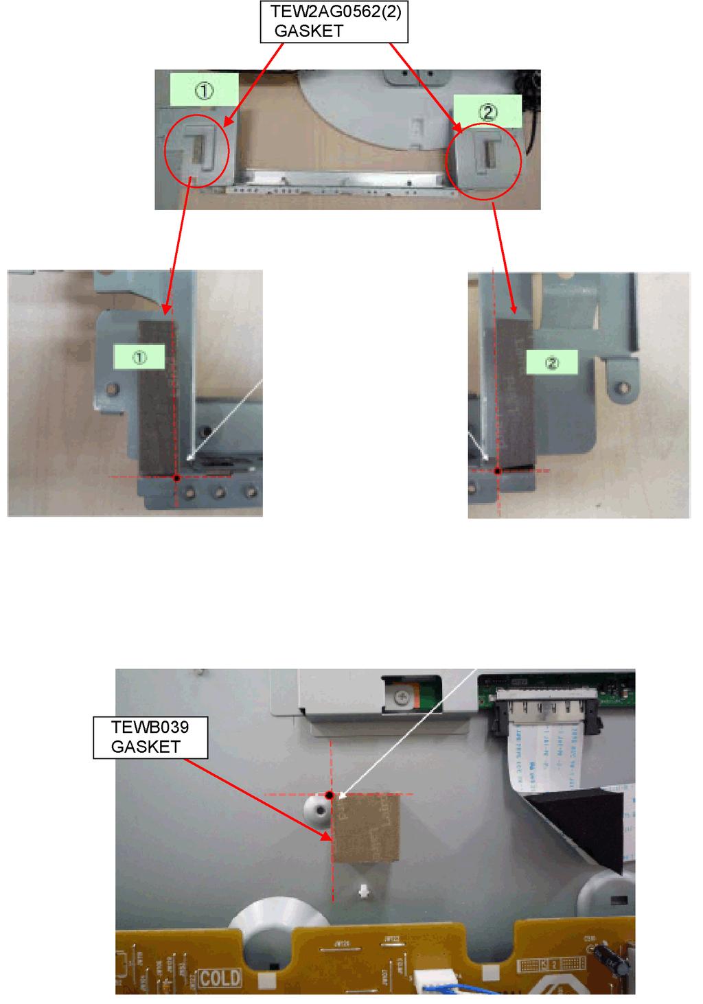
19 7.. EMI processing (7 inch) 9

20 0

21

22

23

24 7.. EMI processing ( inch)

25
26 6
27 8 Measurements and Adjustments 8.. Voltage chart of P-board 8.. Voltage chart of A-board VOLTAGE TET POINT PECIFICATION (Reception state).6 TP8. ± 0.6 V.0 TP80. ± 0.6 V.6 TP60.6 ± 0.06 V.8 TP60.8 ± 0.09 V.09 TP600. ± 0.6 V.77 TP0 ± 0. V TP8 9 ± 0. V 0.9 TP800 0 ±. V 7. TP 7 ± 0.8 V 7. TP7 7 ± 0.8 V.97 TP ± 0.6 V.9 TP ± 0.6 V.709 TP.6 ± 0.8 V.706 TP9.6 ± 0.8 V VOLTAGE TET POINT PECIFICATION (Reception state) TBV TP8. ± 0.6 V TB.V TP80. ± 0.6 V UB.V TP60.6 ± 0.06 V UB.8V TP60.8 ± 0.09 V UB.V TP600. ± 0.6 V UBV TP0 ± 0. V UB9V TP8 9 ± 0. V BT0V TP800 0 ±. V P7V TP 7 ± 0.8 V OUNDVCC TP7 7 ± 0.8 V DTVV TP ± 0.6 V PANELV TP ± 0.6 V V TP.6 ± 0.8 V TUNER6V TP9.6 ± 0.8 V 7
 *BACK LIGHT +0 Remarks Remarks <Inspection>. Enter ervice mode, and select MAIN_ADJ PICTURE.")
28 8.. Picture level adjustment (RF) Instrument Name. REMOTE TRANMITTER. Ex. ignal (plit color bar) Adjustment or Inspection Procedure <procedure>. Receive the split color bar. (creen mode: ZOOM or FULL Picture mode: DYNAMIC AI: OFF AI Picture: OFF) *BACK LIGHT +0 Remarks Remarks <Inspection>. Enter ervice mode, and select MAIN_ADJ PICTURE. Volume UP/DOWN key makes GAIN displayed under PICTURE to set. Pushing the remote controller [OK] key for about seconds, GAIN is suited to the adjustment value automatically. 8.. Picture level adjustment (VIDEO) Instrument Name. REMOTE TRANMITTER. Video signal generator (00% Color bar) Adjustment or Inspection Procedure <procedure>. Receive 00% color bar. (APECT: ZOOM or FULL, Picture mode: VIVID, AI Picture: OFF) *BACK LIGHT MAX VALUE Remarks Remarks <Inspection>. Enter Factory adjustment mode, and select ADJUT CONTRAT. Volume UP/DOWN key makes GAIN value displayed on the right of CONTRAT to set. Pushing the remote controller [OK] key for about seconds, GAIN is suited to the adjustment value automatically. 8.. Picture level adjustment (YUV) Instrument Name. REMOTE TRANMITTER. Component Video signal generator (00% Color bar 080i) Adjustment or Inspection Procedure <procedure>. Receive 00% color bar. (APECT: ZOOM or FULL, Picture mode: VIVID, AI Picture: OFF) *BACK LIGHT MAX VALUE Remarks Remarks <Inspection>. Enter Factory adjustment mode, and select ADJUT CONTRAT. Volume UP/DOWN key makes GAIN value displayed on the right of CONTRAT to set. Pushing the remote controller [OK] key for about seconds, GAIN is suited to the adjustment value automatically. 8
29 9 Block Diagram 9.. Main Block Diagram A-BOARD 7MHz Digital/ Analog Tuner V IFD/ L,R FRONT END T erial EEPWP EEPROM CLOCK GEN 7MHz 7MHz DDR DRAM HDMI HDMI IIC HDMI HDMI T erial REET HDMI V,Y,C TV-V TV-L,R HDMI Analog video signal HDMI Receiver A/D converter AUDIO PROCEOR Digital video signal Peaks Litep (MAIN MCU+VIDEO IGNAL PROCEOR) FLAH MEMORY VIDEO VIDEO L,R V L,R D CARD I/F UB+.V D CARD COMP Y,PB,PR L,R AV W Y,PB,PR COMP L,R DTV-L,R DTV Digital Auido MONITOR OUT L,R MON OUT L,R IECOUT HEADPHONE HP AUDIO_RT erial BO BI D BOOT PEAKER A OPT OUT OPT PWM AUIDO AMP REET EEPROM TB Micom GenX DTV+V DCDC UB+.V DCDC UB+.V UB+.8V UB+.V UB+.V UB+.8V V-BOARD OUND O (LED:9 TIME) REMOTE LED REMOTE LED TB+.V A0 V0 REMOTE CONTROL LED Control Panel Assy K A0 KEY LOD VIDEO A07 FOR FACTORY UE ZWEI A FOR FACTORY UE ZW_PLL.V UB+.V MAIN+.V ENE (LED:8 TIME) UB+.V ENE (LED:7 TIME) LVD PANEL+V A7 FOR FACTORY UE V RELAY UB_ON UB+V UB+9V DTV+V UB+V ENE (LED:6 TIME) UB+9V ENE (LED: TIME) DTV+V ENE (LED: TIME) LCD PANEL A UB_ON TUNER6V P A0 UB_ON INV O PANEL CONTROL (LED: TIME) 7V DTVV O (LED: TIME) PANEL BACK LIGHT Power Unit TB+V TV_O TB_REET TB+.V INVERTER CIRCUIT OVP_DET UB+V P A0 INV O P P6 P +V AC CORD DC70V 9
30 9.. Block (/) Diagram A-BOARD JK00 JK800 JK0 COMPONETVIDEO VIDEO PC IN D_Y D_PB D_PR D_L D_R V_V V_L V_R V_Y V_C V_V V_L V_R R G B TU800 TUNER ANALOG ANT IC800 FRONTEND IIC DIGITAL IFD/ IF AGC DIGITAL DEMODULATOR IC00 AV W IIC UB.V UB.V VIDEO Y/C/V L/R IC8 VIDEO V BT0V UBV BT0V L/R COMP Y/PB/PR IIC Control Panel Assy V-BOARD D00A POWER LED OUT RM00 GND REMOCON VCC K V0 A0 KEY KEY A0 REMOTE R_LED_ON TB.V KEY KEY REMOTE R_LED_ON L/R PC RGB TV V L/R UBV UB9V MAIN OUT Y/CVB, PB/C,PR, RBG CVB L/R DTV L/R 7 P A0 INV_O INV_ON ADIM IC600 +.V UB+.V UB.V D66 D67 INV_PWM TUNER6V DTVV IC60 UB.8V D6 D6 D7 D76 +.8V UB.V Power Unit P 0 TUNER6V A0 0 IC0 UBV +V +.V D68 D69 IC80 O/RT/TB.V XRT TUNER6V RELAY Q UB ON PANEL ON 6 UB_ON V 7V 7V DTVV 6 P7V D708 DTVV D7 D708 D7 D7 DCDC_CTL OVP DET O ENE +.V INV ON TB.V TV O TB RT 7 9 DTVV 7 DTVV 9 PANEL_ON IC09 UB9V IC0 REET Q P P P6 LCD PANEL PANEL+V A AC CORD PANEL BACK LIGHT PANEL CONTROL LVD Dual 0 9 0
31 9.. Block (/) Diagram A-BOARD JK0 JK00 CN00 HDMI HDMI HDMI +V CEC DDC IIC TMD +V CEC DDC IIC TMD +V CEC DDC IIC TMD IC0 HDMI HDMI HDMI AUDIO PROCEOR HDMI Rx/AD CONV. PWM OUT OUNDVCC IC0 AUDIO AMP PEAKER OUT L(+) L(-) R(+) R(-) A PEAKER(L) PEAKER(R) OUNDVCC MAIN VIDEO O DET DDCA_IIC HP OUT HEADPHONE DDCB_IIC DDCD_IIC +.V +.8V +.8V PDIF OUT +.V D00 OPT.Audio out UBV IC +.V IIC IIC AV L/R TV L/R Digtal Video PDIF IN DTV I IN UB.V IC +.V IC V HDMI_CEC HDMI V DET DDCB_IIC HDMI V DET DDCA_IIC HDMI V DET DDCD_IIC IC +.8V IC700 TEMP ENOR IIC UB.V JK80 D DATA D CARD 7 REMOTE KEY KEY INV_O INV_ON PANEL_ON R_LED_ON UB_ON IC0 INV O (LED: TIME) UB+.V ENE (LED:7 TIME) O (LED: TIME) IC0 TANDBY MCU GenX8 HDMI_CEC HDMI_CEC_PU_ON +V(HDMI) DET,, DDCA_IIC DDCB_IIC DDCD_IIC BO BI D07 ERIAL INV_PWM ADIM PWM CTL REET I IECOUT Digital Video T erial PWM A PWM K BO BI ERIAL I/F +.V +.8V +.V D DATA CLOCK CPU BU I/F IC800 DDR I/F Peaks-litep (MAIN MCU+VIDEO IGNAL PROCEOR) IIC IIC IIC IIC IIC IIC IC800 CLOCK GEN IC80 FLAH MEMORY IC800,0 DDR DRAM IC80 EEPROM CN0 A A07 FOR FACTORY UE FOR FACTORY UE FOR FACTORY UE EEPROM IIC LOD TB+.V DTV+V ENE (LED: TIME) RGB:0bit UB+9V ENE (LED: TIME) OUND_O TB_REET (LED:9 TIME) OUNDVCC UB+V ENE (LED:6 TIME) MAIN_ON MAIN+.V ENE (LED:8 TIME) Q7 UBV IC ZW_PL.V ZW_PL.V IC00 ZWEI IC +.V ZW.V ZW.V +.V IC0 PI-FLAH DTVV IC ZW.8V IC0,0 DDR DRAM +.8V ZW.V 9 +.V LVD Dual OD VIDEO
32

33 0 Wiring Connection Diagram 0.. Caution statement. Caution: Please confirm that all flexible cables are assembled correctly. Also make sure that they are locked in the connectors. Verify by giving the flexible cables a very slight pull. 0.. Wiring ( inch)

34 0.. Wiring (7 inch)
35 chematic Diagram.. chematic Diagram Notes
36 % % % % % +.. A-Board (/) chematic Diagram A B C D E F C807 0.u 6V C807 0.u 6V C807 0.u 6V C8070 6V 0.u MNW007 LOD OUT (for ZWEI) C800 6V 0.u UB.V UB.V DRCK LRCK ADCCK ADIN LCID LCCK VICVB VICVB VICVB VICVB0 VICK0F VICK08F VIP0 VIP VIP VIP VIP VIP6 VIP7 VIP8 VIP9 LVD I/F C8069 0V 8p C8067 6V 0.0u L8009 J0JHC00000 L8008 R808 AUDIO IF PEAK LITE IC800 TO / C807 6V 0.u k TO 0/ J0JHC00000 IC800 C DRCK IC800 E LRCK IC800 B ADCCK IC800 A ADIN IC800 B LCID IC800 A LCCK IC800 E VICVB IC800 E0 VICVB IC800 F0 VICVB IC800 E9 VICVB0 IC800 F9 VICK0F IC800 E8 VICK08F IC800 F8 VIP0 IC800 E7 VIP IC800 F7 VIP IC800 D6 VIP IC800 D VIP IC800 F VIP6 IC800 E VIP7 IC800 D VIP8 IC800 F VIP9 DMIX0 RCK0 LRCK0 IECOUT0 R800 0 R800 6 R806 k R C800 6.V u IC800 G LPFOUT C8068 6V 0.u IC800 P6 DPAVDD IC800 H MVAVDD IC800 J MVAV IC800 P AGAVDD IC800 P AGAV IC800 E LVVDD IC800 F LVVDD IC800 E TCLKN IC800 B TAN IC800 C TBN IC800 D TCN IC800 E6 TCLKP IC800 B6 TAP IC800 D6 TCP IC800 G6 TEP IC800 H AUDCLK IC800 G LPFIN IC800 D DAUDIO IC800 B RCK0 IC800 F LRCK0 IC800 C DACCK0 IC800 A0 IECOUT0 IC800 R ATCPOUT IC800 P AVCOIN IC800 R6 N.C.(DPAV) IC800 E LVVDD IC800 F TDN IC800 G TEN IC800 C6 TBP IC800 F6 TDP IC800 A DMIX0 C8007 6V 0.u C8008 6V 0.u C800 0V 0u C u 6V C8009 0V 0u UB.V C80 6V 0.u! LODOUT LODOUT LODOUT LODOUT0 LODOUT9 LODOUT8 LODOUT7 LODOUT6 LODOUT LODOUT LODOUT LODOUT LODOUT LODOUT0 LODOUT_CLK_O LODOUT_H_O PORT9[0] LODOUT_YM LODOUT_V_I LODOUT_CLK_I LODOUT_H_I R80 0 A-BOARD (/) TXN/A0PMG (7inch) TXN/A0PNG (inch) PWM UB.V L800 J0JHC00000 IC800 N7 VDDR IC800 R7 VDDR IC800 T VDDR IC800 U6 VDDR IC800 AB VDDR IC800 AC VDDR IC800 AD VDDR IC800 AE VDDR IC800 AF VDDR IC800 U N.C.(DPAVDD) IC800 M7 VDDA IC800 U VDDA IC800 T7 VDDA IC800 C DACV IC800 A DACV IC800 C DACVDD IC800 E DACVDD C80 6V 0.u FOR ZWEI VIDEO TO / MVCLK MHYNC MVYNC VOP9 VOP8 VOP7 VOP6 VOP VOP VOP VOP VOP VOP0 VOP9 VOP8 VOP7 VOP6 VOP VOP VOP VOP VOP VOP0 VOP9 VOP8 VOP7 VOP6 VOP VOP VOP VOP VOP VOP0 TO 6/ VOUTENB IIC I/F TO / CL0 DA0 CL DA BT0 BT XEC XEC D CARD I/F TO / DCLK DCD DCMD DDAT0 DDAT DDAT DDAT DWP IC800 A MVCLK IC800 C MHYNC IC800 E0 MVYNC IC800 E8 VOP9 IC800 B8 VOP8 IC800 F7 VOP7 IC800 A8 VOP6 IC800 C7 VOP IC800 B7 VOP IC800 A7 VOP IC800 E7 VOP IC800 C VOP IC800 E6 VOP0 IC800 B0 VOP9 IC800 E9 VOP8 IC800 A0 VOP7 IC800 C9 VOP6 IC800 F8 VOP IC800 B9 VOP IC800 A9 VOP IC800 C8 VOP IC800 F6 VOP IC800 A6 VOP0 IC800 B VOP9 IC800 D0 VOP8 IC800 A VOP7 IC800 C VOP6 IC800 F9 VOP IC800 B VOP IC800 A VOP IC800 C0 VOP IC800 C6 VOP IC800 B6 VOP0 IC800 H6 VOUTENB IC800 M CL0 IC800 M DA0 IC800 N CL IC800 N DA IC800 AB8 BT0 IC800 AD6 BT IC800 AD XEC IC800 AC XEC C80 6V 0.u C80 6V 0.u C80 6V 0.u C80 6V 0.u C80 6.V u C806 6.V u C807 0V 0u C8077 6V 0.u IC800 AF DCLK IC800 AD DCD IC800 AD DCMD IC800 AB DDAT0 IC800 AE DDAT IC800 AB DDAT IC800 AA DDAT IC800 AE DWP IC800 F LVV IC800 F LVV IC800 G LVV.8V_DDRI/F C8078 6V 0.u C8079 6V 0.u C8080 6V 0.u UB.8V L800 DA CL DA CL J0JHC00000 FOR ADV79 TO 9/ VICKOUT VICLK VIP0 VIP VIP VIP0 VIP VIP VIP VIP VIP6 VIP7 VIP8 VIP9 VIVYNC VIHYNC VIP VIP VIP VIP VIP6 VIP7 VIP8 VIP9 VIENB VICLK VIP VIP VIP VIP VIP6 VIP7 VIP8 VIP9 VIP NAND I/F TO / NANDRYBY JTAG IC800 K VDDIO IC800 K6 VDDIO IC800 M VDDIO IC800 M VDDIO IC800 N VDDIO IC800 P VDDIO IC800 R VDDIO IC800 T VDDIO IC800 U VDDIO IC800 V VDDIO IC800 W6 VDDIO IC800 Y VDDIOCK IC800 Y VDDIO IC800 AA VDDIO IC800 AB9 VDDIO IC800 AB VDDIO IC800 AB VDDIO IC800 AC8 VDDIO IC800 AC VDDIO IC800 AD7 VDDIO IC800 AD VDDIO IC800 AD VDDIO IC800 AE6 VDDIO IC800 AE VDDIO IC800 AF0 VDDIO IC800 AF6 VDDIO TO / TM TRT TCK TDI IC800 A8 VICKOUT IC800 C9 VICLK IC800 G6 VIP0 IC800 F VIP IC800 E VIP IC800 F VIP0 IC800 A9 VIP IC800 B9 VIP IC800 B8 VIP IC800 C8 VIP IC800 A7 VIP6 IC800 C6 VIP7 IC800 C VIP8 IC800 A VIP9 IC800 D VIVYNC IC800 D VIHYNC IC800 B VIP IC800 C VIP IC800 A VIP IC800 B VIP IC800 A VIP6 IC800 B VIP7 IC800 C VIP8 IC800 C VIP9 IC800 E VIENB IC800 E VICLK IC800 B0 VIP IC800 C0 VIP IC800 B7 VIP IC800 C7 VIP IC800 A6 VIP6 IC800 B6 VIP7 IC800 A VIP8 IC800 B VIP9 IC800 G VIP IC800 AC XNFCE IC800 AD XNFWE IC800 AD XNFRE IC800 AE NFALE IC800 AB6 NFCLE IC800 AF XNFWP IC800 AC6 NANDRYBY IC800 P GTCPOUT IC800 H TCPOUT IC800 D TTAIO C808 6V 0.u C809 6V 0.u C800 6V 0.u C80 6V 0.u C80 6.V u C80 0V 0u C80 0u 0V IC800 R TM IC800 R TRT IC800 R6 TCK IC800 R TDO IC800 T TDI IC800 AE DTCPOUT C8076 6V 0.u UB.V UB.V L800 J0JHC00000 IC800 N0 VDD IC800 P0 VDD IC800 R0 VDD IC800 R VDD IC800 R VDD IC800 R VDD IC800 T0 VDD IC800 T VDD IC800 T VDD IC800 T VDD IC800 U0 VDD IC800 U VDD IC800 U VDD IC800 U VDD IC800 AA VDD IC800 AB VDD IC800 AC VDD IC800 AD VDD IC800 AE VDD IC800 AF VDD L800 J0JHC00000 C807 0V 0u INCH ONLY UFFIX:AB TP00 VIP0 VIP VIP *R09 0 VIVYNC VIHYNC VIP VIP0 VIP0 VIENB R0 R R R R R R6 R7 R8 R9 G0/Y0 G/Y G/Y G/Y G/Y G/Y G6/Y6 G7/Y7 G8/Y8 G9/Y9 TP007 B0/CbCr0 B/CbCr B/CbCr B/CbCr B/CbCr B/CbCr B6/CbCr6 B7/CbCr7 B8/CbCr8 B9/CbCr9 IC800 K7 LVVDD C80 6V 0.u C806 6V 0.u C807 6V 0.u C808 6V 0.u C809 6V 0.u C800 6.V u C80 6.V u C80 0V 0u UB.V L8007 J0JHC00000 B PORT (ub Video Input or Address) TO / VIP VIP VIP VIP VIP VIP6 VIP7 VIP8 VIP9 VIP VIP VIP VIP VIP6 VIP7 TP8000 VIP8 TP800 VIP9 Analog Video I/F TP80 % R R876 7 R C800 6.V u C800 6.V u ERIAL I/F R800 0k % R800 k UB.V L800 J0JHC00000 IC800 AA8 VDD IC800 AA9 VDD IC800 A VDD IC800 A6 VDD IC800 B VDD IC800 C VDD IC800 D7 VDD IC800 D8 VDD IC800 D6 VDD IC800 D7 VDD IC800 D VDD IC800 E VDD IC800 F VDD IC800 F VDD IC800 F UBVDD IC800 F0 VDD IC800 G VDD IC800 H VDD IC800 J6 VDD IC800 K6 VDD IC800 N6 VDD IC800 P6 VDD IC800 R VDD IC800 T VDD IC800 U6 VDD IC800 AC0 VDD IC800 AC VDD IC800 E6 VIP EA IC800 H VIP EA08 IC800 J VIP EA09 IC800 H VIP EA0 IC800 H VIP EA IC800 K VIP6 EA IC800 J VIP7 EA IC800 K VIP8 EA IC800 J VIP9 EA IC800 K VIP EA6 IC800 L VIP EA7 IC800 K VIP EA8 IC800 L VIP EA9 IC800 L VIP6 EA0 IC800 M6 VIP7 EA IC800 L VIP8 EA IC800 M VIP9 EA IC800 F VIHYNC DRAM_CHK IC800 H VIVYNC DRAM_CHK IC800 G VICLK UB.V IC800 E V V R IC800 B MVDACO C U B IC800 F MVDACO Y Y G IC800 D MVDACO Cmp Cmp Cmp C800 6.V u R k UB.V IC800 E VVREF IC800 B MVIREF IC800 A VCOMP IC800 D MVCOMP TO / BI0 IC800 C BI0 BO0 IC800 D BO0 TO 6/ BI IC800 A BI BO IC800 B BO IC800 A V IC800 N V IC800 B V IC800 N6 V IC800 C V IC800 N V IC800 D V IC800 P V IC800 D9 V IC800 P V IC800 D0 V IC800 P V IC800 D UBDP IC800 P V IC800 D UBDM IC800 P V IC800 D8 V IC800 P7 V IC800 D9 V IC800 R V IC800 E V IC800 R V IC800 E V IC800 P V IC800 F6 V IC800 R V IC800 F V IC800 R6 V IC800 G7 V IC800 T V IC800 G V IC800 T6 V IC800 H V IC800 T V R808 0 MCLK AE IC800 POD,CI I/F TTEL AC IC800 CABY00006 TO / EA0 IC800 T EA0.8V_DDRI/F TO / IC800 AD XEC6 EA IC800 T EA XEC7 IC800 AE XEC7 FE_XRT EA IC800 T6 EA C806 IC800 AB XEXDMK0 CH0DM0 CH0DM0 6V EA IC800 T EA MMDM0 L IC800 IC800 B UDM 0.u IC800 A VDD IC800 AE XEXDMR0 CH0DM CH0DM EA IC800 U EA MMDM M6 IC800 IC800 F LDM IC800 E VDD IC800 A V EA IC800 U EA IC800 M9 VDD IC800 E V EA6 IC800 U EA6 IC800 A8 UDQ IC800 J9 VDD CH0DQ0 IC800 J V EA7 IC800 U EA7 IC800 B7 UDQ C80 IC800 R VDD CH0DQ0 V IC800 N V TP86 IC800 AE6 XRT0 MMDQ0 L6 IC800 IC800 E8 LDQ 68u ED0 IC800 U ED0 CH0DQ CH0DQ IC800 P9 V TP86 IC800 AC8 XDTR0 MMDQ M IC800 IC800 F7 LDQ IC800 J VDDL ED IC800 V ED TP86 IC800 AF6 XDR0 ED IC800 V ED C80 IC800 A7 VQ TP876 IC800 AB9 XDCD0 CH0DQ 0.u ED IC800 V ED IC800 B9 DQ 6V IC800 B VQ TP8 IC800 AD7 XCT0 CH0DQ7 ED IC800 V ED IC800 B DQ C807 IC800 A9 VDDQ IC800 B8 VQ TP8 IC800 AC9 XRI0 CH0DQ0 CH0DQ 6V ED IC800 W ED MMDQ0 L IC800 IC800 D9 DQ 0.u IC800 C VDDQ IC800 D VQ TP86 IC800 AE7 TXD0 CH0DQ CH0DQ ED6 IC800 W ED6 MMDQ L IC800 IC800 D DQ IC800 C VDDQ IC800 D8 VQ TP87 IC800 AF7 RXD0 CH0DQ CH0DQ ED7 IC800 V6 ED7 MMDQ K IC800 IC800 D DQ IC800 C7 VDDQ IC800 E7 VQ CH0DQ CH0DQ0 ED8 IC800 W ED8 MMDQ K IC800 IC800 D7 DQ0 IC800 C9 VDDQ IC800 F VQ CH0DQ CH0DQ6 ED9 IC800 W ED9 TP88 IC800 AD8 MTCLK MMDQ K IC800 IC800 C DQ9 C808 IC800 E9 VDDQ IC800 F8 VQ CH0DQ CH0DQ 6V ED0 IC800 Y ED0 TP89 IC800 AE8 MTD MMDQ J IC800 IC800 C8 DQ8 0.u IC800 G VDDQ IC800 H VQ CH0DQ6 ED IC800 Y ED TP860 IC800 AA0 MTRT MMDQ6 J6 IC800 IC800 G VDDQ IC800 H8 VQ CH0DQ7 CH0DQ8 ED IC800 W ED IC800 AF8 MTCMD MMDQ7 J IC800 IC800 F9 DQ7 IC800 G7 VDDQ CH0DQ8 CH0DQ ED IC800 Y ED IC800 AB0 MTEL MMDQ8 N IC800 IC800 F DQ6 IC800 G9 VDDQ IC800 J7 VDL CH0DQ9 CH0DQ ED IC800 AA ED IC800 AA MTD0 MMDQ9 N IC800 IC800 H9 DQ C806 CH0DQ0 CH0DQ 0u ED IC800 AA ED IC800 AE9 MTRT0 MMDQ0 N IC800 IC800 H DQ CH0DQ CH0DQ 0V IC800 AF9 MTCMD0 MMDQ N6 IC800 IC800 H DQ XERE IC800 Y XERE CH0DQ CH0DQ IC800 AB MTEL0 MMDQ P IC800 IC800 H7 DQ XEWE0 IC800 AA XEWE0 CH0DQ CH0DQ0 IC800 AD9 MTCLK0 MMDQ P IC800 IC800 G DQ IC800 AB XEWE CH0DQ CH0DQ9 IC800 A NC MMDQ P IC800 IC800 G8 DQ0 IC800 Y XEDK IC800 AD0 CHCLK PWM CH0DQ IC800 E NC MMDQ P6 IC800 IC800 AB ERXW IC800 AA CHVAL IC800 R NC IC800 AB ECLK IC800 AE0 CHPYNC PWM CH0ODT R807 IC800 R7 NC R8770 0k IC800 K9 ODT IC800 AA EZ0 IC800 AF0 CHDATA 0 IC800 R8 NC R877 0k R806 7 CH0A0 CH0CK IC800 AC EZ MMA0 W IC800 IC800 J8 CK R807 7 CH0A CH0XCK MMA V6 IC800 IC800 K8 CK TO / R808 7 CH0A MMA AA6 IC800 XEC0 IC800 AA XEC0 R809 7 CH0A CH0CKE MMA T IC800 IC800 K CKE CH0A0 IC800 AC XEC R CH0A IC800 M8 A0 MMA V IC800 CH0A XEC IC800 AC XEC R806 7 CH0A CH0BA0 IC800 M A MMA U IC800 IC800 L BA0 CH0A XEC IC800 AB XEC R806 7 CH0A6 CH0BA IC800 M7 A MMA6 Y6 IC800 IC800 L BA CH0A COMMON PORT.etc R806 7 CH0A7 CH0BA IC800 N A IC800 N XNMIRQ CARD_NMIRQ MMA7 U6 IC800 IC800 L NC CH0A R867 0k R806 7 CH0A8 IC800 N8 A IC800 N XIRQ CARD_IRQ MMA8 Y IC800 CH0A R806 7 CH0A9 CH0XWE IC800 N A MMA9 U IC800 IC800 K WE CH0A6 TO / R CH0A0 CH0XRA IC800 N7 A6 MMA0 T6 IC800 IC800 K7 RA CH0A7 XIRQ IC800 N XIRQ FE_IRQ R CH0A CH0XCA IC800 P A7 MMA V IC800 IC800 L7 CA CH0A8 R CH0A CH0XC0 IC800 P8 A8 MMA U IC800 IC800 L8 C CH0A9 TO 9/ IC800 P A9 CH0A0 XIRQ IC800 P XIRQ HDMI_IRQ IC800 M RMCO (FBI_ON/GC6 IRQ) IC800 M A0 CH0ODT IC800 J VREF CH0A IC800 P7 A IC800 AF BOOTWAP R80 C800 CH0A TO 6/ 0.u IC800 R A TO / 0k 6V VIP IC800 J VIP DBOOT XRT IC800 D XRT R CH0BA0 MMBA0 T IC800 IC800 L6 VIP OD_FLAG R CH0BA CH0CKE MMBA V IC800 R807 7 CH0BA MMBA T IC800 R807 7 CH0XWE R808 MMXWE R IC800 0k R807 7 CH0XRA MMXRA W IC800 R807 CH0XCA TO / 7 MMXCA U IC800 UB.V R8076 CH0XC CH0CLK 7 IC800 AF CH0CLK MMXC W IC800 DDR_ R800 7 CH0XC0 CH0VAL IC800 AE CH0VAL MMXC0 R IC800 R CH0CKE CH0PYNC IC800 AD CH0PYNC MMCKE R IC800 IC800 R809 CH0DATA IC800 AF CH0DATA.k R8078 CH0ODT CABY MMODT AA IC800 IC800 G VIP0 DDR_CLK_EL CH0CK CH0ODT R8097 MMCK AC6 IC800 IC800 K9 ODT CH0XCK 0 CH0A0 MMXCK AB6 IC800 CH0CK IC800 M8 A0 IC800 J8 CK CH0A IC800 AF I0CLK R8098 0k CH0XCK IC800 M A MMMONBAA IC800 IC800 K8 CK CH0A IC800 AB7 I0VAL IC800 M7 A R8099 0k CH0A IC800 AE I0PYNC MMMONAAB IC800 IC800 N A TO / CH0CKE CH0A IC800 AF I0DATA IC800 K CKE IC800 N8 A VICLK IC800 J VICLK EEPROM_WP MMPCLKEXT AC IC800 CH0A.8V_DDRI/F CH0BA0 IC800 N A TP87 IC800 AE IVAL (BI) IC800 L BA0 CH0A6 IC800 H6 VIP0 ETHER_IRQ CH0BA IC800 N7 A6 TP87 IC800 AC7 IPYNC (BO) TO / IC800 L BA CH0A7 CH0BA IC800 P A7 IC800 AD ICLK VIP0 IC800 K VIP0 DIPEN R808 R808 IC800 L NC C80 CH0A8 IC800 P8 A8 IC800 AF IDATA (GC6_IRQ) 7 00 CH0XWE 0V CH0A9 IC800 K WE 0u IC800 P A9 TO / MMRDRV AF IC800 CH0XRA CH0A0 IC800 K7 RA IC800 M A0 VIENB IC800 G VIENB POWER_DET CH0XCA CH0A TP0 MMRODT AE6 IC800 IC800 L7 CA IC800 P7 A CH0XC CH0A IC800 L8 C IC800 R A VREF C80.8V_DDRI/F 6V IC800 J VREF 0.u IC800 A VDD MMVCAL Y IC800 C80 C80 IC800 E VDD 0.u R80 0.u R800 6V IC800 M9 VDD 6V IC800 J9 VDD CPU BU I/F CH,I IF CLOCK GEN IC800 J V IC800 U7 V MMVREF0 M IC800 C809 IC800 R VDD IC800 A V C807 R80 IC800 K0 V IC800 V V 0.u 6V IC800 E V MMVREF AB8 IC UB.V 6V 0.u IC800 K V IC800 V V C808 IC800 A9 VDDQ IC800 J V IC800 K V IC800 W6 V 6V C809 IC800 C VDDQ IC800 N V 0.u 6V IC800 K V IC800 W V CH0DM 0.u IC800 C VDDQ IC800 P9 V IC800 B UDM IC800 K V IC800 W V L800 CH0DM IC800 C7 VDDQ J0JHC00000 IC800 F LDM IC800 K V IC800 Y6 V CH0DM IC800 C9 VDDQ IC800 A7 VQ MMDM AE9 IC800 IC800 K6 V IC800 Y V CH0DM C800 IC800 E9 VDDQ IC800 B VQ MMDM AF8 IC800 IC800 A8 UDQ 6V IC800 L V IC800 AA6 V CH0DQ 0.u IC800 G VDDQ IC800 B8 VQ IC800 B7 UDQ IC800 L0 V IC800 AA7 V CH0DQ IC800 G VDDQ IC800 D VQ X800 R809 MMDQ AF9 IC800 IC800 E8 LDQ IC800 L V IC800 AA V H0J CH0DQ CH0DQ IC800 G7 VDDQ IC800 D8 VQ 0k MMDQ AD8 IC800 IC800 L V IC800 AA8 V R8087 IC800 F7 LDQ IC800 G9 VDDQ IC800 E7 VQ 0k IC800 L V IC800 AA V CH0DQ0 IC800 F VQ CH0DQ6 IC800 B9 DQ IC800 L V IC800 AA V MMDQ6 AB0 IC800 CH0DQ8 X 6 IC800 J VDDL IC800 F8 VQ C807 CH0DQ7 X IC800 B DQ IC800 L V IC800 AB7 V 0.u MMDQ7 AC9 IC800 CH0DQ7 C80 IC800 H VQ 6V CH0DQ8 IC800 D9 DQ 6V IC800 L6 V 0 IC800 AB V R8090 VDD MMDQ8 AE0 IC800 CH0DQ 0.u IC800 H8 VQ CH0DQ9 IC800 D DQ IC800 L7 V IC800 AB V 0k MMDQ9 AD0 IC800 CH0DQ R8086 CH0DQ0 IC800 D DQ IC800 L V IC800 AC V C806 00k MMDQ0 AA9 IC800 CH0DQ6 IC800 J7 VDL VIN 6V 0.u CH0DQ IC800 D7 DQ0 IC800 L V IC800 AC V VC7 J IC800 MMDQ AA0 IC800 CH0DQ9 C80 VDD CH0DQ IC800 C DQ9 IC800 A NC IC800 M V IC800 AC6 V CLK7 H IC800 C80 0.0u 6V MMDQ AF IC800 CH0DQ VDD 6.V CH0DQ IC800 C8 DQ8 IC800 E NC IC800 M0 V IC800 AC0 V CK7 K IC800 GND u MMDQ AD IC800 6 GND CH0DQ IC800 R NC IC800 M V IC800 AC V CK7D AD IC800 C808 MMDQ AA7 IC800 CH0DQ8.76/M 0V CH0DQ IC800 F9 DQ7 IC800 R7 NC IC800 M V IC800 AC V L8 C u MMDQ AC7 IC800 CH0DQ7 7M 0 CH0DQ6 IC800 F DQ6 IC800 R8 NC IC800 AD9 V 6V.9M IC800 M V 0 R809 MMDQ6 AE7 IC800 CH0DQ 0.0u CH0DQ7 IC800 H9 DQ IC800 M V IC800 AD V 7 8 COMM 9 7M MMDQ7 AF7 IC800 CH0DQ R809 CH0DQ8 IC800 H DQ IC800 M V IC800 AD6 V MMDQ8 AB6 IC800 CH0DQ6 7 CH0DQ9 IC800 H DQ IC800 M6 V IC800 AE8 V MMDQ9 AA6 IC800 CH0DQ CH0DQ0 IC800 H7 DQ IC800 M V IC800 AE V IC800 MMDQ0 AD6 IC800 CH0DQ0 CH0DQ IC800 G DQ IC800 N V IC800 AE V MMDQ AF6 IC800 CH0DQ9 IC800 G8 DQ0 IC800 N V IC800 AF V C0ZBZ00000 L8 IC800 N V IC800 AF V 0 IC800 N V IC800 AF V CLOCK GEN DDR_0 IC
37 A-Board (/) chematic Diagram UBV FOR FACTORY UE A7 XEC UB.V R866 R866 0k 0k AA_ED0 AA_ED AA_ED AA_ED AA_ED AA_ED AA_ED6 AA_ED7 R090 EXBHV60JV TO / ED0 ED ED ED ED ED ED6 ED7 From PEAK-LiteII TO / NANDRYBY UB.V L800 J0JHC R80 0k AA_EA7 C800 6V 0.u AA_ED AA_ED7 AA_ED AA_ED6 AA_ED AA_ED AA_ED AA_ED C80 6V 0.u AA_ED AA_ED AA_ED0 AA_ED AA_ED9 AA_ED AA_ED8 AA_ED0 AA_XERE AA_XEC0 AA_EA C87 6V 0.u TP87 TP87 R86 R86 TO / BI0 BO0 XEC UB.V AA_ED8 AA_ED9 AA_ED0 AA_ED AA_ED AA_ED AA_ED AA_ED R09 EXBHV60JV R68 EXBHV7JV ED8 ED9 ED0 ED ED ED ED ED R8 0k R8 0 A 6 NC A NC A A6 A BYTE# A Vss 6 A DQ/A- 7 0 A DQ7 8 9 A0 DQ 9 A9 8 DQ6 0 7 A8 DQ A9 6 DQ A0 DQ WE# DQ REET# Vcc A DQ 6 WP#/ACC DQ 7 RY/BY# 0 DQ0 8 A8 9 DQ 9 8 A7 DQ9 0 A7 7 DQ A6 6 DQ8 A DQ0 A OE# A Vss A CE# 6 A A0 7 NC 0 NC 8 NC 9 Vio *IC80 FLAH TVRQAB AA_EA AA_EA AA_EA6 AA_EA AA_EA AA_EA AA_EA AA_EA AA_EA0 AA_EA9 AA_EA0 AA_EA AA_XEWE0 AA_XRT AA_EA AA_EA9 AA_EA8 AA_EA8 AA_EA7 AA_EA6 AA_EA AA_EA AA_EA AA_EA AA_EA AA_XEC0 XEC XEC R88 R87 TO / VIP TO / XEC0 XEC XEC AA_EA0 AA_EA AA_EA AA_EA AA_EA AA_EA AA_EA6 AA_EA7 AA_EA8 AA_EA9 AA_EA0 AA_EA AA_EA AA_EA AA_EA AA_EA AA_EA6 AA_EA7 AA_EA8 AA_EA9 AA_EA0 AA_EA AA_EA AA_EA R079 EXBHV60JV R089 EXBHV60JV EA0 EA EA EA EA EA EA6 EA7 VIP VIP VIP VIP VIP6 VIP7 VIP8 VIP9 VIP VIP VIP VIP VIP6 VIP7 VIP8 VIP9 EA8, UV0 EA9. UV EA0, UV EA, UV EA, UV EA, UV EA, UV6 EA, UV7 EA6, Y0 EA7, Y EA8, Y EA9, Y EA0, Y EA, Y EA, Y6 EA, Y7 AA_XERE AA_XEWE0 R89 R80 TO / XERE XEWE0 R08 EXBHV60JV AA_XRT TO / AA_XRT TP80 C806 6V 0.u UB.V NC VCC 8 R86.7k TP8 TO / NC NC 7 WC 6 CL R89 6 VICLK EEPROM_WP V DA R8 *IC80 TVRQAA EEPROM AD_DA AD_CL R8 IC R87.k R88.k TP8 TP8 AD_DA0 AD_CL0 AD_DA AD_CL AD_DA AD_CL AD_DA AD_CL UB.V R80.7k R88.7k UB.V R87.k R86.k R88 R89 R80 R8 R8 R8 R8 R8 TO / DA0 CL0 DA CL BT0 DA BT CL XEC DA XEC CL from LiteII D_CARD TO / DDAT DDAT DDAT0 DDAT R87 EXB8VJX AE_DDAT AE_DDAT AE_DDAT0 AE_DDAT AE_DWP AE_DCD AE_DDAT AE_DDAT0 AE_DCLK AE_DCMD AE_DDAT AE_DDAT L807 J0JHC00000 UB.V AD_DA0 AD_CL0 TO / AD_DA0 AD_CL0 DWP DCD DCMD DCLK R87 68 R87 68 R87 68 R87 0 AE_DWP AE_DCD AE_DCMD AE_DCLK R866 EXBHV0JV AD_DA AD_CL TO,0/ AD_DA AD_CL L809 J0JAC TP80 TP8 TP8 TP8 TP8 TP8 TP86 TP87 AD_DA AD_CL TO,0,/ AD_DA AD_CL AD_DA AD_CL TO,6/ AD_DA AD_CL R868 R869 R870 R87 R87 EXB8V0JX C8! TXN/A0PMG (7inch) A-BOARD (/) TXN/A0PNG (inch) R8 0k UB.V TO / JTAG TDI TM TRT 6V 0.u C8 6V 7u + C87 6V.u Around Peaks ExBU, BootROM/NOR FLAH, NAND, UPPORT CARD DIGITAL(NAND,BOOT,ETC) R08 0k R7 0k R069 0k TCK W.P. W.P.0 DWP D.W D.W 0 DDTC DDAT DDAT0 GND DCLK NO.V GND DCMD DDAT DDAT JK80 KNA09E00080 D CARD LOT
38 + % % % % + P P % % % % % % % % % /W P P P P P P + + % %.. A-Board (/) chematic Diagram OUNDVCC C6 C6 V V 0.u 0.u UB9V C6 C6 UB9V TP8 TP8 PA00 KH6A00 R98 0 C98 6V 0u L8 GC70MA0077 VOUT NC VDD EXT V D MAX78900L Q BCFNG00000 R96 8k C7 0V 0u R97 6k C8 0V 000p L8 GC00MA007 D6 B0BC09000 BT0V! TXN/A0PMG (7inch) A-BOARD (/) TXN/A0PNG (inch) CRNo CRNo CRNo P->A DCDC.V.8V.V L60 GC00MA00 L60 J0JHC00000 DTVV 0V 0V u u DTVV C68 C69 6V 6V u u V UBV C660 C66 6V 6V u u MAIN9V C66 0V u TB.V C669 6V u C668 C666 C667 6V 6V 6V u u u C66 6V u TBV C670 C67 C67 C67 u u u u 6V 6V 6V 6V MAIN.V C66 6V u UBV C66 6V u C67 C67 u u 6V 6V TO 6,/ AG_TV_MAIN_ON P7V DTVV R k R 0k R C V u IC8 C0DBAJB0000 BT0V C 0V 0u R 6k Vin Vc Q C800L D MAJ00L Vo GND Vadj IC09 C0DBEHE0000 UB9V OUND VCC Q7 BCHRD00000 R 6.k R 0k TP09 TP7 R 0k C V u UB9V OUNDVCC L0 J0JHC00000 VJ600 VJ60 R60 k R6 0k R6 k R69 7k R60 7k R60 7.k C6 0V 70p C6 0V 0p R60 68 C6 V 0.0u R6 6k C6 6V u R6.6 R6 6k C66 6V 0.07u C606 6V u R60.6 R60 0k C607 C60 0V V 0p 6800p UB.V_.8V CTL CB C DRVH FB LX VO DRVL 0 ILIM VCC 6 9 GND VB 7 8 CVBLPF PGND 8 7 CTL DRVL 9 6 ILIM LX 0 VO DRVH FB CB C TET IC60 IC600 C0DBAYY0080 UB.V CTL CB C DRVH FB LX VO DRVL 0 ILIM VCC 6 9 GND VB 7 8 CVBLPF PGND 8 7 CTL DRVL 9 6 ILIM LX 0 VO DRVH FB CB C TET C0DBAYY0080 VJ60 VJ60 VJ60 VJ60 C6 0V.7u VJ606 VJ607 C60 C66 6V 0.u C67 6V 0.u C6 6V 0.u C60 6V 0.u C60 6V 0.u Q60 BMBDDA0000 G G G G Q60 D D D D BMBDDA0000 G G D D D D D D D D Q600 BMBDDA0000 C69 6V 0u L60 GCRZ0000 C68 6V 0u L60 GCRZ00007 C6 6V 0u L600 GCR7Z000 C V 0u C69.V 68u C68.V 68u C60 V 68u C6 6V 0u C6 6V 0u TP60 TP60 L608 GC00MA0077 TP600 C60 6V 0.u C6 6V 0.u D68 MAZ8070ML D6 MAZ8070ML D66 MAZ8070ML UB.V D69 MAJ00L UB.8V D6 MAJ00L C67 6V 0.u D67 MAJ00L UB.V C69 6V 0.u C6 6V 7u PA60 ERBER0U C6 6V 0.0u ZA00 TEA69 ZA0 TEA69 ZA0 TEA69 ZA0 TEA69 ZA0 TEA69 ZA06 TEA69 ZA07 TEA69 ZA TEA69 ZA6 TEA69 ZA08 TEA69 ZA09 TEA69 ZA0 TEA69 ZA TEA69 ZA TEA69 ZA TEA69 ZA TEA69 UB9V UB.V ZA0 ZA6 ZA00 ZA ZA06 ZA07 ZA0 ZA0 ZA0 ZA ZA ZA ZA08 ZA ZA09 ZA0 MAIN_9V TP6 MAIN9V R6 0 MAIN.V TP00 MAIN.V R00 0 ZA0 C676 C677 C678 6V 6V 6V u u u UB.V C680 C68 C679 6V 6V 0.u 6V 0.u 0.u OUNDVCC C68 6V 0.u C68 6V 0.u C68 6V 0.u TO LCD PANEL A0 TO GND P-BOARD ADIM (P) INV_ON INV_PWM INV_O R6 0 R6 0 R66 0 R67 0 R09 00 R68.k TP TP TP TP R69 TO 7/ INV_PWM TO 7/ INV_ADIM TO 6/ AG_INVERTER_ON TB.V R70 TO 6/ AG_INVERTER_O DTVV R k R 0k R C V u R k Q C800L PANELV Q BCHRD00000 TP 0V.7u R 70 PNLV DTVV TUNER6V D7 MAZ8800ML D7 MAZ800ML P7V D708 MAZ800ML D7 D76 MAJ00L C66 6V 0.u MAJ00L D708 MAJ00L C68 6V 0.u TUNER6V C0 V u R09 0k D07 MAJ00L UBV IC0 C0DBEYY0006 (FIN) Vin Vc Vo Vadj GND R0.7k R0 R0 k k TP0 UBV C08 0V 0u R07 C68 V 0.u TO P-BOARD TP (P) A0 TP8 TO 6/ AG_DTV_XRT 0k R08 Q08 C800L C09 V 0.0u MAIN9V P7V C686 C69 C69 6V V V 0.u 0.u 0.u DTVV C687 C698 C699 C700 6V 0V 0V 0V 0.u 000p 000p 000p UBV C688 C689 6V 6V 0.u 0.u MAIN.V C690 C69 6V 6V 0.u 0.u GND GND RELAY N.C TV_UB_ON 6 GND 7 GND 8 V 9 V 0 GND GND 7V 7V GND GND DTVV 6 DTVV 7 8 GND 9 DTVV TUNER6V 0 GND TUNER6V TP88 R6 TP 0 P7V TP TP8 C6 V 0.u TP TP86 C6 6V 0u DTVV VJ06 VJ07 TP87 TUNER6V TP9 C6 6V 0.u V D00 MAF000L Q B0709AL R07.7k TBV C00 6V 0.0u R06 R99 TO 6/ AG_PANEL_VCC_ON TO / AMP_MUTE TO 6/ AG_AUDIO_MUTE TO / (POWER_DET) VIENB TO 6/ AG_W_OFF_DET TO,6/ TB_RT UB.V R86 R8 00 TBV L80 J0JYC TO / AA_XRT R8 R8 TO / 00 7 XRT UB9V TB.V TP80 L8 J0JYC UB.V R80 C80 6V 0.0u VJ86 VJ8 VJ8 R8 6k R8 0k VJ8 R87 R88 8k C9 6V u C8 0V 0u C8 0V u Analog AIC IC80 CZBZ C86 PeaksRT 8 6V 0.07u CD INV_ON 7 DCDC_CTL Panal_VCC_ON 6 DCDC_CTL AMPMUTE DTVV_REF AMONMUTE DTVV C88 6 AUDIOMUTE 6V CD 0.07u 7 FAT_B TV_O 8 W_OFF_DET O_ENE C89 9 TBRT 0 O_IN 0V 0u 0 MONTBV 9 UBV R9 0 BVCC 8 UB_ON TB.V 7 OVP TBV 6 V C9 GND CD 6V 0.u R90.7k V C9 0V u DTVV R89 k C87 6V u UBV VJ80 R9 68 R9 k R9 68k VJ8 TO / AP_OVP_DET TO 6/ AG_O TO 6/ AG_TV_UB_ON Q07 C800L R78 0 D7 MAJ00L R79 0k R70 k D7 MAJ00L P7V V TP TP8 C97 6V 0.u Q D060AL.7k R
39 % % +.. A-Board (/) chematic Diagram! TXN/A0PMG (7inch) A-BOARD (/) TXN/A0PNG (inch) OPERATE Q0 AUDIO CHIP, POWER AMP CRNo O BADCE0000 TP R AG_OUND_O To O 0 R0 C0 R0.k 6V.9k 0.u MAIN.V R0.k MUTE OPERATE AMP_MUTE C0 6V 0.u R 0k R R0 0k Q0 BABCF000 OPERATE AUDIO AMP IC0 CAB C6 V 70u OUNDVCC R. C7 0V 0.0u TO 6/ HP_ROUT HP_ROUT PWM_READY TP0 MUTE PWM_READY MUTE OPERATE R 0k UBV_MUTE R PWM_Q_L+ PWM_Q_L- REET R7 0 TBY PWM_READY NC MUTE R06 0 MUTE NC PWM_A 6 NC 7 PWM_B 8 NC C 9 VREG 0V u 0 GND NC Thermal Pad 6 PVD PVD OUT_CH_P BOOT_CH_P VDDA 9 BOOT_CH_N OUT_CH_N PGND 8 PGND 7 PGND 6 PGND C C0 0V V 0.u u 0V C7 0.u C0 V u 0V C9 0.u L00 u GC0MA09 L0 u GC0MA09 C V 0.u C V 0.u C7 0V 0.0u C9 0V 0.0u R08. C77 0V 0.0u C87 0V 000p C89 0V 000p TP TP TP TP TO PEAKER A L+ L- R+ R- HP_LOUT DTV_ROUT DTV_LOUT HP_LOUT DTV_ROUT DTV_LOUT PWM_Q_R+ PWM_Q_R- OPERATE O R 0 D0 MAJ00L PWM_B OUT_CH_N NC6 0V C BOOT_CH_N 0.u C07 PWM_A V VDDA u NC7 0V C BOOT_CH_P 0.u 6 NOD_THERM OUT_CH_P 7 NOD_OUTHDN 0 PVD 8 NC8 9 PVD C9 C09 0V V 0.u u L0 u GC0MA09 L06 u GC0MA09 C V 0.u C V 0.u R. C 0V 0.0u C79 0V 0.0u C8 0V 0.0u C7 0V 0.0u C8 0V 000p C8 0V 000p R. R0 DTV_ROUT C9 6V 0.0u TO / MAIN_L MAIN_R C6 0V 0u C6 0V 0u R00 8k R0 8k AUXINR AUXINL AUXOUTR AUXOUTL R0 C8 6V 0.0u HPOUTR HPOUTL R09 0k R09 0k C099 6.V 00u + + C098 6.V 00u L00 J0JHC00000 R08 0k DTV_LOUT HP_ROUT TO 6/ AG_ODU_DET/KEY R7 00k C0 0V 000p R8 0k Q09 B0709AL R77 6k R7 6k TBV D0 MAJ7800L TB.V R79 0k R8 00 R8 R8 70k 70k R80 60 D07 MAJ00L D06 D08 MAJ00L MAJ00L C07 6.V 0u W RT IC0 C0EBF0000 C08 6.V 0u VDD CD OUT V C09 0V 00p R8 00 DVDDIO_.V R0 0k MUTEB TO 0/ ADV770 PWM_READY PWMB PWMA PWMB PWMA AREETB R7 EXB8V0JX Q_R- >> PWM_Q_R- Q_R+ >> PWM_Q_R+ Q_L- >> PWM_Q_L- Q_L+ >> PWM_Q_L+ L006 J0JHC00000 R07 0k Q06 D060AL HP_LOUT TO / AG_KEY TO,6/ TB_RT R07 00 Q06 B0709AL R AMP_MUTE MUTE Q06 D060AL R06 00 R08 M R09 70k R0 k C0 0V u TO 6/ AG_OUND_O AG_OUND_O AG_AUDIO_XRT AG_AUDIO_XRT >> REETB R.k UBV D0 MAJ00L R6 C V 0u MUTE Q0 OPERATE BADCE0000 R9 00 UBV_MUTE C99 0V 0u R6 00k R60 k MUTE TO / AMP_MUTE OPERATE AMP_MUTE PWM_READY AG_AUDIO_XRT
40 % % % % % % % VCC Vin GND % % %.6. A-Board (/) chematic Diagram PC IN TO,6/ AD_DA AD_CL TO 6/ DA CL TO 6/ AG_RQ-GENX DA CL TP87 R87 TP86 R86 TP8 R8 TP8 R8 TP8 R8 TP8 TBV 8 7 Lite DA 6 Lite CL GenX DA GenX CL GND FOR A FACTORY UE KKA08AA078 TP0 TP0 TP06 JK0 KFBA R08 9.7k R0 7 R0 7 TP0 C098 0u 0V D079 EZJP0V080GA TP0 C099 0u 0V D080 EZJP0V080GA TP0 C07 0V 0u PC_R PC_G PC_B INV LED R779 TP UB9V D7:' D7:7' R *D7 *D7 BAEB0000 BAEB0000 R778 TO 6/ 0k G-PANEL_LED_ON Q9 R777 C800L D08 EZJP0V080GA R09.7k 0 R06 7 D08 EZJP0V080GA D08 EZJP0V080GA TO 6/ PC_H PC_V MAIN_Y/CVB MAIN_PB/C MAIN_PR RGB_CVB TO 9/ PC_H PC_V MAIN_Y/CVB MAIN_PB/C MAIN_PR RGB_CVB R8 0 AG_KEY TO / AG_KEY R9 0 AV_V AV_C C0 AV_Y C009 AV_V AV DET C007 PC_R PC_H PC_G PC_V PC_B PC_H PC_V D0 TP06 EZJP0V080GA A0 TO CONTROL PANEL AY (K) TP07 D0 EZJP0V080GA 0.u 6V 0u 0V 0u 0V UBV UB9V C0 6V 0.u 0 9 C07 0V R u 7 6 R0 0 R C008 0V 0u R007 0 R006 k R00 68 R00 00 R00 68 R00 00 R MAIN.V C 0V 00u C6 6V 0.u L00 J0JHC00007 L00 J0JHC00007 D00 K7AAAY00000 DIGITAL AUDIO OUT DRIVE IC C7 6V 0.u UB.V R7 0k R 6 TO 0/ PDIF_OUT TO,0/ AD_DA AD_CL TO,0,/ AD_DA AD_CL MAIN_Y/CVB PC_H MAIN_PB/C PC_V MAIN_PR RGB_CVB TO / MAIN_R MAIN_L C06 6V 0.u C0 6V 0.u R09 0 R00 0 DA R08 CL R09 R0 68 R CL 0 GND G/CY/CVBout HD out B/PB/Cout VD out R/Prout 6 VCCV AG CVBout 7 8 Y/Y+C/CVBout 9 out AG CVBout 0 C/Y+C/CVBout GND AG CVBout CVB/Y+Cout VCC9V 6 G/CY/Y/CVBout7 7 O T DET B/Cin DET G/Yin T DET CVBin T DET B/Cin DET G/Yin GND R/Cin DET Yin BG CVBin T DET CVBin T DET DA FBout/T DET0 tate out AU_GND Rout Lout C07 0V 0u CVBin VCCV R Rout Lout Rout C08 0V 0u C09 0V 0u C060 0V u C06 0V u IC00 CAB00008 AV W C06 0V u C06 0V u C066 0V u C067 0V u C068 0V u Rin HDin Gin R9in L9in R8in Lout Rout 6 Lout 7 AU/Vcc 8 Lin 9 Rin 60 Lin 6 Rin 6 Lin 6 Rin 6 Lin 6 Rin 66 Lin 67 Rin 68 L6in 69 R6in 70 L7in 7 R7in 7 L8in R08 0 R09 0 R060 0 R06 0 R06 0 R06 0 R066 0 R067 0 R068 0 R069 0 C069 0V u PRin 97 HD VD/FBKMUTE 96 CYin 9 L DET 9 PBin 9 T DET6 9 PRin/R 9 T DET7 90 CYin/G 89 L DET 88 PBin/B 87 VCCV 86 Cin 8 T DET8 8 Yin 8 T DET9 8 CVBin 8 VCC9V 80 CVBin VDin Bin GND FBin/O CVBin7 FBin/O R08 k R077 0 R096 0 R097 0 C080 6V 0.u R09 0 R09 0 C077 0V u AC_TV_V C097 0V C09 0V C09 0V 0u 0u 0u R06 0k D_PR D_Y D_PB D_L D_R D_Y D_PB D_PR AV_V AV_L AV_R D00 EZJP0V080GA D00 EZJP0V080GA D0 EZJP0V080GA D06 EZJP0V080GA D07 EZJP0V080GA D0 EZJP0V080GA D0 EZJP0V080GA D0 EZJP0V080GA R7 80k R7 80k R7 7 R76 7 R78 7 R9 7 R60 80k R6 80k TP00 TP00 TP00 TP00 TP00 TP0 TP006 TP007 TP008 JK00 KAK7A0000 COMPONENT L IN L R R G Y Y PB PB PR PR G AV C IN Y W G Y C Y-G C-G G V AV IN V L L R R G GND RM TB.V R_LED TO V-BOARD (V) A0 TP88 TP8 L8 J0JCC TP8 TP8 C88 0V 000p TO 6/ AG_RMIN TB.V TO 6/ AG_R_LED_ON R877 AD_CL AD_DA R878 CL 6 DA GND A0 MAIN.V A VDD C800 6V 0.u IC700 CZBZ00077 TEMP ENOR TO / DTV_LOUT DTV_ROUT AC_TV_L AC_TV_R AV_L AV_R AV_L AV_R D_L D_R AV_C D70 EZJP0V080GA C70 0V u R70 7 TP009 TP00 C AV_Y Y D70 EZJP0V080GA R70 7 G Y C D70 EZJP0V080GA TP00 CY-G! TXN/A0PMG (7inch) A-BOARD (/) TXN/A0PNG (inch) TO / AC_TV_V AC_TV_R AC_TV_L AC_TV_V AC_TV_R AC_TV_L TO / HP_LOUT HP_ROUT HP_DET AV DET AV_V AV_L AV_R R708 0 R709 0 D70 EZJP0V080GA R D0 EZJP0V080GA R6 D06 EZJP0V080GA R6 D06 EZJP0V080GA D708 EZJP0V080GA D709 EZJP0V080GA 7 80k 80k TP0 TP0 TP0 TP08 TP09 TP0 TP0 G V-W V V-G L L-G R R-G V L R JK800 KAK6B
RSDW08 & RDDW08 series
 /,, MODEL SELECTION TABLE INPUT ORDER NO. INPUT VOLTAGE (RANGE) NO LOAD INPUT CURRENT FULL LOAD VOLTAGE CURRENT EFFICIENCY (Typ.) CAPACITOR LOAD (MAX.) RSDW08F-03 344mA 3.3V 2000mA 80% 2000μF RSDW08F-05
Surface Mount Multilayer Chip Capacitors for Commodity Solutions
 Surface Mount Multilayer Chip Capacitors for Commodity Solutions Below tables are test procedures and requirements unless specified in detail datasheet. 1) Visual and mechanical 2) Capacitance 3) Q/DF
50 inch Class 1080p Plasma HDTV
 ORDER NO. MTCE B Canada: B inch Class p Plasma HDTV Model No. TH-PZU GPFDU Chassis Matsushita Electric Industrial Co., Ltd. All rights reserved. Unauthorized copying and distribution is a violation of
the total number of electrons passing through the lamp.
 1. A 12 V 36 W lamp is lit to normal brightness using a 12 V car battery of negligible internal resistance. The lamp is switched on for one hour (3600 s). For the time of 1 hour, calculate (i) the energy
Capacitors - Capacitance, Charge and Potential Difference
 Capacitors - Capacitance, Charge and Potential Difference Capacitors store electric charge. This ability to store electric charge is known as capacitance. A simple capacitor consists of 2 parallel metal
Technical Specifications
 FLX-8X8A Chassis Technical Specifications Modular Input Cards... FLX-BI4, FLX-DI4, FLX-HI4, FLX-RI4 Analog Audio... Balanced or Unbalanced Stereo Audio (20 Hz to 20 khz) Supported Outputs Modular Output
SPBW06 & DPBW06 series
 /,, MODEL SELECTION TABLE INPUT ORDER NO. INPUT VOLTAGE (RANGE) NO LOAD INPUT CURRENT FULL LOAD VOLTAGE CURRENT EFFICIENCY (TYP.) CAPACITOR LOAD (MAX.) SPBW06F-03 310mA 3.3V 0 ~ 1500mA 81% 4700μF SPBW06F-05
DC-DC Constant Current Step-Down LED driver LDD-300L LDD-350L LDD-500L LDD-600L LDD-700L CURRENT RANGE
 SPECIFICATION ORDER NO. LDD-00L LDD-0L LDD-00L LDD-00L LDD-700L CURRENT RANGE 00mA 0mA 00mA VOLTAGE RANGE Note. ~ VDC for LDD-00~700L/LW ; ~ 8VDC for LDD-00~700LS CURRENT ACCURACY (Typ.) ±% at VDC input
15W DIN Rail Type DC-DC Converter. DDR-15 series. File Name:DDR-15-SPEC
 DIN Rail Type DC-DC Converter ± : DIN Rail Type DC-DC Converter SPECIFICATION MODEL OUTPUT INPUT PROTECTION ENVIRONMENT SAFETY & EMC (Note 5) OTHERS DC VOLTAGE RATED CURRENT CURRENT RANGE RATED POWER RIPPLE
DC-DC Constant Current Step-Down LED driver LDD-300L LDD-350L LDD-500L LDD-600L LDD-700L CURRENT RANGE
 SPECIFICATION ORDER NO. LDD-00L LDD-0L LDD-00L LDD-00L LDD-700L CURRENT RANGE 00mA 0mA 00mA 00mA VOLTAGE RANGE Note. ~ VDC for LDD-00~700L/LW ; ~ 8VDC for LDD-00~700LS CURRENT ACCURACY (Typ.) ±% at VDC
38BXCS STANDARD RACK MODEL. DCS Input/Output Relay Card Series MODEL & SUFFIX CODE SELECTION 38BXCS INSTALLATION ORDERING INFORMATION RELATED PRODUCTS
 DCS Input/Output Relay Card Series STANDARD RACK MODEL 38BXCS MODEL & SUFFIX CODE SELECTION 38BXCS MODEL CONNECTOR Y1 :Yokogawa KS2 cable use Y2 :Yokogawa KS9 cable use Y6 :Yokogawa FA-M3/F3XD32-3N use
Aluminum Electrolytic Capacitors (Large Can Type)
") Aluminum Electrolytic Capacitors (Large Can Type) Snap-In, 85 C TS-U ECE-S (U) Series: TS-U Features General purpose Wide CV value range (33 ~ 47,000 µf/16 4V) Various case sizes Top vent construction
Aluminum Electrolytic Capacitors (Large Can Type) Snap-In, 85 C TS-U ECE-S (U) Series: TS-U Features General purpose Wide CV value range (33 ~ 47,000 µf/16 4V) Various case sizes Top vent construction
Aluminum Electrolytic Capacitors
 Aluminum Electrolytic Capacitors Snap-In, Mini., 105 C, High Ripple APS TS-NH ECE-S (G) Series: TS-NH Features Long life: 105 C 2,000 hours; high ripple current handling ability Wide CV value range (47
LR Series Metal Alloy Low-Resistance Resistor
 Tel : 881745 Fax : 881749 LR Series Metal Alloy LowResistance Resistor This specification is applicable to lead free, halogen free of RoHS directive for metal alloy lowresistance resistor. The product
15W DIN Rail Type DC-DC Converter. DDR-15 s e r i e s. File Name:DDR-15-SPEC
 DIN Rail Type DC-DC Converter ± : DIN Rail Type DC-DC Converter SPECIFICATION MODEL OUTPUT INPUT PROTECTION ENVIRONMENT SAFETY & EMC (Note 5) OTHERS NOTE DC VOLTAGE RATED CURRENT CURRENT RANGE RATED POWER
0.635mm Pitch Board to Board Docking Connector. Lead-Free Compliance
 .635mm Pitch Board to Board Docking Connector Lead-Free Compliance MINIDOCK SERIES MINIDOCK SERIES Features Specifications Application.635mm Pitch Connector protected by Diecasted Zinc Alloy Metal Shell
SAW FILTER - RF RF SAW FILTER
 FEATURES - Frequencies from 0MHz to 700MHz - Custom specifications available - Industry standard package configurations - Low-loss saw component - Low amplitude ripple - RoHS compliance - Electrostatic
Multilayer Chip Inductor
 Features -Monolithic structure for high reliability -High self-resonant frequency -Excellent solderability and high heat resistance Construction Applications -RF circuit in telecommunication and other
65W PWM Output LED Driver. IDLV-65 series. File Name:IDLV-65-SPEC
 ~ A File Name:IDLV65SPEC 07050 SPECIFICATION MODEL OUTPUT OTHERS NOTE DC VOLTAGE RATED CURRENT RATED POWER DIMMING RANGE VOLTAGE TOLERANCE PWM FREQUENCY (Typ.) SETUP TIME Note. AUXILIARY DC OUTPUT Note.
Metal thin film chip resistor networks
 Metal thin film chip resistor networks AEC-Q200 Compliant Features Relative resistance and relative TCR definable among multiple resistors within package. Relative resistance : ±%, relative TCR: ±1ppm/
Instruction Execution Times
 1 C Execution Times InThisAppendix... Introduction DL330 Execution Times DL330P Execution Times DL340 Execution Times C-2 Execution Times Introduction Data Registers This appendix contains several tables
1000 VDC 1250 VDC 125 VAC 250 VAC J K 125 VAC, 250 VAC
 Metallized Polyester Film Capacitor Type: ECQE(F) Non-inductive construction using metallized Polyester film with flame retardant epoxy resin coating Features Self-healing property Excellent electrical
LR Series Metal Alloy Low-Resistance Resistor
 LR Series Metal Alloy LowResistance Resistor This specification is applicable to lead free, halogen free of RoHS directive for metal alloy lowresistance resistor. The product is for general purpose. The
(REV:01) RYOBI 48 Volt Lawn Mower Model No. RY14110 Replacement Parts List
 RYOBI 48 Volt Lawn Mower Model No. RY14110 Replacement Parts List") 9800-86 2-0-0 (REV:0) RYOBI 48 Volt Lawn Mower Model No. RY0 Replacement Parts List RYOBI RY0 48 volt lawn mower 3 38 39 44 39 36 34 36 42 38 39 3 4 37 34 3 43 2 32 0 8 9 2 4 33 8 7 6 3 6 7 22 8 20 3 30
9800-86 2-0-0 (REV:0) RYOBI 48 Volt Lawn Mower Model No. RY0 Replacement Parts List RYOBI RY0 48 volt lawn mower 3 38 39 44 39 36 34 36 42 38 39 3 4 37 34 3 43 2 32 0 8 9 2 4 33 8 7 6 3 6 7 22 8 20 3 30
Metal Oxide Varistors (MOV) Data Sheet
 Data Sheet") Φ SERIES Metal Oxide Varistors (MOV) Data Sheet Features Wide operating voltage (V ma ) range from 8V to 0V Fast responding to transient over-voltage Large absorbing transient energy capability Low clamping
Φ SERIES Metal Oxide Varistors (MOV) Data Sheet Features Wide operating voltage (V ma ) range from 8V to 0V Fast responding to transient over-voltage Large absorbing transient energy capability Low clamping
LR(-A) Series Metal Alloy Low-Resistance Resistor
 Series Metal Alloy Low-Resistance Resistor") LR(A) Series Metal Alloy LowResistance Resistor This specification is applicable to lead free, halogen free of RoHS directive for metal alloy lowresistance resistor. The product is for general purpose.
LR(A) Series Metal Alloy LowResistance Resistor This specification is applicable to lead free, halogen free of RoHS directive for metal alloy lowresistance resistor. The product is for general purpose.
Potential Dividers. 46 minutes. 46 marks. Page 1 of 11
 Potential Dividers 46 minutes 46 marks Page 1 of 11 Q1. In the circuit shown in the figure below, the battery, of negligible internal resistance, has an emf of 30 V. The pd across the lamp is 6.0 V and
(REV:01) RYOBI 48 Volt Lawn Mower Model No. RY14110A Replacement Parts List
 RYOBI 48 Volt Lawn Mower Model No. RY14110A Replacement Parts List") 9000-7 9-- (REV:0) RYOBI 4 Volt Lawn Mower Model No. RY0A Replacement Parts List RYOBI RY0A 4 VOLT LAWN MOWER 3 3 39 44 39 3 34 3 42 3 39 3 4 37 34 3 43 2 0 37 2 33 32 3 9 7 22 30 4 7 3 20 9 3 2 2 27 2
9000-7 9-- (REV:0) RYOBI 4 Volt Lawn Mower Model No. RY0A Replacement Parts List RYOBI RY0A 4 VOLT LAWN MOWER 3 3 39 44 39 3 34 3 42 3 39 3 4 37 34 3 43 2 0 37 2 33 32 3 9 7 22 30 4 7 3 20 9 3 2 2 27 2
Summary of Specifications
 Snap Mount Large High CV High Ripple 85 C Temperature The series capacitors are the standard 85 C, large capacitance, snap-in capacitors from United Chemi-Con. The load life for the series is 2,000 hours
NMBTC.COM /
 Common Common Vibration Test:... Conforms to JIS C 60068-2-6, Amplitude: 1.5mm, Frequency 10 to 55 Hz, 1 hour in each of the X, Y and Z directions. Shock Test:...Conforms to JIS C 60068-2-27, Acceleration
SMD Transient Voltage Suppressors
 SMD Transient Suppressors Feature Full range from 0 to 22 series. form 4 to 60V RMS ; 5.5 to 85Vdc High surge current ability Bidirectional clamping, high energy Fast response time
65W PWM Output LED Driver. IDPV-65 series. File Name:IDPV-65-SPEC
 IDPV65 series ~ A File Name:IDPV65SPEC 07060 IDPV65 series SPECIFICATION MODEL OUTPUT OTHERS NOTE DC VOLTAGE RATED CURRENT RATED POWER DIMMING RANGE VOLTAGE TOLERANCE PWM FREQUENCY (Typ.) SETUP TIME Note.
OWA-60E series IP67. 60W Single Output Moistureproof Adaptor. moistureproof. File Name:OWA-60E-SPEC
 Single Output Moistureproof Adaptor OWA-60E series IP67 Ⅱ Ⅱ moistureproof I File Name:OWA-60E-SPEC 0-04- Single Output Moistureproof Adaptor OWA-60E series SPECIFICATION MODEL OWA-60E- OWA-60E- OWA-60E-0
Digital motor protection relays
 Digital motor protection relays Specification DMP -S & DMP -Sa DMP -T & DMP -Ta Model No. DMP06-S/Sa DMP60-S/Sa DMP06-T/Ta DMP60-T/Ta Wiring Screw type Tunnel type Panel mount Unit or Extension Note1)
TRC ELECTRONICS, INC LED Driver Constant Voltage 45W MEAN WELL IDLV-45 Series
 LED Driver Constant Voltage 5W MEAN WELL IDLV5 Series ~ A File Name:IDLV5SPEC 0707 TRC ELECTRONICS, INC..888.6.95 LED Driver Constant Voltage 5W MEAN WELL IDLV5 Series TRC ELECTRONICS, INC. SPECIFICATION
Output Power: W. Exclusively distributed by Powerstax
 R Series, 50-150W Input Ranges : 9-75 VDC : Single - Dual /, / /, / Triple / ±, /, / ±0, Quad ± / ±, ± / : 50-150 W FEATURES General: to 100 Watts Wide Input Range : 10-7dc 2:1 & 3:1 Input Range High Conversion
Fixed Inductors / AL TYPE
 .Features: 1.Coating epoxy resin that ensures the humidity resistance to be long life. 2.Contribute to be high Q and selfresonant frequencies.applications: 1.Electronics products. 2.Communication equipment.
IDPV-45 series. 45W PWM Output LED Driver. File Name:IDPV-45-SPEC S&E
 IDPV5 series S&E ~ A File Name:IDPV5SPEC 0805 IDPV5 series SPECIFICATION MODEL OUTPUT INPUT OTHERS NOTE DC VOLTAGE RATED CURRENT RATED POWER DIMMING RANGE VOLTAGE TOLERANCE PWM FREQUENCY (Typ.) SETUP TIME
UNIVERSITY OF CALIFORNIA. EECS 150 Fall ) You are implementing an 4:1 Multiplexer that has the following specifications:
 You are implementing an 4:1 Multiplexer that has the following specifications:") UNIVERSITY OF CALIFORNIA Department of Electrical Engineering and Computer Sciences EECS 150 Fall 2001 Prof. Subramanian Midterm II 1) You are implementing an 4:1 Multiplexer that has the following specifications:
UNIVERSITY OF CALIFORNIA Department of Electrical Engineering and Computer Sciences EECS 150 Fall 2001 Prof. Subramanian Midterm II 1) You are implementing an 4:1 Multiplexer that has the following specifications:
Surface Mount Aluminum Electrolytic Capacitors
 FEATURES CYLINDRICAL V-CHIP CONSTRUCTION LOW COST, GENERAL PURPOSE, 2000 HOURS AT 85 O C NEW EXPANDED CV RANGE (up to 6800µF) ANTI-SOLVENT (2 MINUTES) DESIGNED FOR AUTOMATIC MOUNTING AND REFLOW SOLDERING
Fixed Inductors / AL TYPE
 .Features: 1.Coating epoxy resin that ensures the humidity resistance to be long life. 2.Contribute to be high Q and selfresonant frequencies.applications: 1.Electronics products. 2.Communication equipment.
THICK FILM LEAD FREE CHIP RESISTORS
 Features Suitable for lead free soldering. Compatible with flow and reflow soldering Applications Consumer Electronics Automotive industry Computer Measurement instrument Electronic watch and camera Configuration
[1] P Q. Fig. 3.1
![[1] P Q. Fig. 3.1](/thumbs/79/80362156.jpg "[1] P Q. Fig. 3.1") 1 (a) Define resistance....... [1] (b) The smallest conductor within a computer processing chip can be represented as a rectangular block that is one atom high, four atoms wide and twenty atoms long. One
1 (a) Define resistance....... [1] (b) The smallest conductor within a computer processing chip can be represented as a rectangular block that is one atom high, four atoms wide and twenty atoms long. One
Smaller. 6.3 to 100 After 1 minute's application of rated voltage at 20 C, leakage current is. not more than 0.03CV or 4 (µa), whichever is greater.
, whichever is greater.") Low Impedance, For Switching Power Supplies Low impedance and high reliability withstanding 5000 hours load life at +05 C (3000 / 2000 hours for smaller case sizes as specified below). Capacitance ranges
Low Impedance, For Switching Power Supplies Low impedance and high reliability withstanding 5000 hours load life at +05 C (3000 / 2000 hours for smaller case sizes as specified below). Capacitance ranges
RoHS 555 Pb Chip Ferrite Inductor (MFI Series) Engineering Spec.
 Engineering Spec.") RoHS 555 Pb Chip Ferrite Inductor (MFI Series) Engineering Spec. PRODUCT DETAIL Electrical Characteristics μh L (Min) Q MHz (Min) SRF Ω DCR IDC ma TEST FREQ: MHz TEST LEVEL: 100 mv Test Instruments HP4291
RoHS 555 Pb Chip Ferrite Inductor (MFI Series) Engineering Spec. PRODUCT DETAIL Electrical Characteristics μh L (Min) Q MHz (Min) SRF Ω DCR IDC ma TEST FREQ: MHz TEST LEVEL: 100 mv Test Instruments HP4291
Data sheet Thick Film Chip Resistor 5% - RS Series 0201/0402/0603/0805/1206
 Data sheet Thick Film Chip Resistor 5% - RS Series 0201/0402/0603/0805/1206 Scope -This specification applies to all sizes of rectangular-type fixed chip resistors with Ruthenium-base as material. Features
First Sensor Quad APD Data Sheet Part Description QA TO Order #
 Responsivity (/W) First Sensor Quad PD Data Sheet Features Description pplication Pulsed 16 nm laser detection RoHS 211/65/EU Light source positioning Laser alignment ø mm total active area Segmented in
4 Way Reversing Valve
 STANDARD 4 Way Reversing Valve SHF series four-way reversing valves are applicable for heat pump systems such as central, unitary and room air conditioners to realize switching between cooling mode and
LS series ALUMINUM ELECTROLYTIC CAPACITORS CAT.8100D. Specifications. Drawing. Type numbering system ( Example : 200V 390µF)
") Snap-in Terminal Type, 85 C Standard Withstanding 3000 hours application of rated ripple current at 85 C. Compliant to the RoHS directive (2011/65/EU). LS Smaller LG Specifications Item Category Temperature
Snap-in Terminal Type, 85 C Standard Withstanding 3000 hours application of rated ripple current at 85 C. Compliant to the RoHS directive (2011/65/EU). LS Smaller LG Specifications Item Category Temperature
Current Sensing Chip Resistor SMDL Series Size: 0201/0402/0603/0805/1206/1010/2010/2512/1225/3720/7520. official distributor of
 Product: Current Sensing Chip Resistor SMDL Series Size: 0201/0402/0603/0805/1206/1010/2010/2512/1225/3720/7520 official distributor of Current Sensing Chip Resistor (SMDL Series) 1. Features -3 Watts
ΚΥΠΡΙΑΚΗ ΕΤΑΙΡΕΙΑ ΠΛΗΡΟΦΟΡΙΚΗΣ CYPRUS COMPUTER SOCIETY ΠΑΓΚΥΠΡΙΟΣ ΜΑΘΗΤΙΚΟΣ ΔΙΑΓΩΝΙΣΜΟΣ ΠΛΗΡΟΦΟΡΙΚΗΣ 19/5/2007
 Οδηγίες: Να απαντηθούν όλες οι ερωτήσεις. Αν κάπου κάνετε κάποιες υποθέσεις να αναφερθούν στη σχετική ερώτηση. Όλα τα αρχεία που αναφέρονται στα προβλήματα βρίσκονται στον ίδιο φάκελο με το εκτελέσιμο
Thin Film Chip Resistors
 FEATURES PRECISE TOLERANCE AND TEMPERATURE COEFFICIENT EIA STANDARD CASE SIZES (0201 ~ 2512) LOW NOISE, THIN FILM (NiCr) CONSTRUCTION REFLOW SOLDERABLE (Pb FREE TERMINATION FINISH) Type Size EIA PowerRating
Metal Oxide Leaded Film Resistor
 Features -Excellent Long-Time stability -High surge / overload capability -Wide resistance range : 0.1Ω~22MΩ -Controlled temperature coefficient -Resistance standard tolerance: ±5% (consult factory for
ALUMINUM ELECTROLYTIC CAPACITORS LKG
 Lug / Snap-in Terminal Type, For Audio Equipment Disigned for high grade audio equipment, giving priority to high fidelity sound quality. The variation expansion of the. TYPE-: The low profile high tone
Modbus basic setup notes for IO-Link AL1xxx Master Block
 n Modbus has four tables/registers where data is stored along with their associated addresses. We will be using the holding registers from address 40001 to 49999 that are R/W 16 bit/word. Two tables that
Strain gauge and rosettes
 Strain gauge and rosettes Introduction A strain gauge is a device which is used to measure strain (deformation) on an object subjected to forces. Strain can be measured using various types of devices classified
 Distributed by: www.jameco.com -800-83-4242 The content and copyrights of the attached material are the property of its owner. Single-Chip Voice Record/Playback Devices 60-, 75-, 90-, and 20-Second Durations
Εγκατάσταση λογισμικού και αναβάθμιση συσκευής Device software installation and software upgrade
 Για να ελέγξετε το λογισμικό που έχει τώρα η συσκευή κάντε κλικ Menu > Options > Device > About Device Versions. Στο πιο κάτω παράδειγμα η συσκευή έχει έκδοση λογισμικού 6.0.0.546 με πλατφόρμα 6.6.0.207.
HIS series. Signal Inductor Multilayer Ceramic Type FEATURE PART NUMBERING SYSTEM DIMENSIONS HIS R12 (1) (2) (3) (4)
 (2) (3) (4)") FEATURE High Self Resonant Frequency Superior temperature stability Monolithic structure for high reliability Applications: RF circuit in telecommunication PART NUMBERING SYSTEM HIS 160808 - R12 (1) (2)
FEATURE High Self Resonant Frequency Superior temperature stability Monolithic structure for high reliability Applications: RF circuit in telecommunication PART NUMBERING SYSTEM HIS 160808 - R12 (1) (2)
Metal Oxide Leaded Film Resistor
 SURFACE TEMP. RISE ( ) Power Ratio(%) MOF0623, 0932, 1145, 1550, 1765, 2485 MOF Series Features -Excellent Long-Time stability -High surge / overload capability -Wide resistance range : 0.1Ω~10MΩ -Controlled
Glass Door Freezers Service Manual
 Turbo Air Speed up the Pace of Innovation CAUTION! PLEASE KEEP POWER SWITCH ON BEFORE OPERATING THIS EQUIPMENT Glass Door Freezers Service Manual Please read this manual completely before attempting to
Shape Square. Tolerance of Varistor Voltage For Varistor voltage<68, Special For Varistor voltage 68, 10% Lead Wire Type Straight Cut Lead
 Leaded Varistor for urge uppression VP eries Operating Temp. : -40 ~ +85 FEATURE Fast response Excellent clamping ratio, high peak current and pulse energy withstanding characteristics, providing strong
AKC Spectrum Analyzer User s Manual.
 AKC-1291 Spectrum Analyzer User s Manual u ano un ao Prohibiting to removal the cover e m Keep the power insert clean RF in/output rating oae o n DC Power nt Restore this instrument 1. Introduction 2.
Chilisin Electronics Singapore Pte Ltd
 hilisin Electronics ingapore Pte Ltd High urrent hip Beads, PBY eries Feature: Our MD High urrent hips Beads is specially designed to with tand large urrents while providing a means of EMI/RFI attenuation
YJM-L Series Chip Varistor
 Features 1. RoHS & Halogen Free (HF) compliant 2. EIA size: 0402 ~ 2220 3. Operating voltage: 5.5Vdc ~ 85Vdc 4. High surge suppress capability 5. Bidirectional and symmetrical V/I characteristics 6. Multilayer
SMD AVR AVR-M AVRL. Variable resistor. 2 Zener diode (1/10) RoHS / / j9c11_avr.fm. RoHS EU Directive 2002/95/EC PBB PBDE
 RoHS / / j9c11_avr.fm. RoHS EU Directive 2002/95/EC PBB PBDE") (1/1) SMD RoHS AVR AVR-M AVRL Variable resistor 2Zener diode Current(A) Positive direction 1 1 1 2 1 3 1 4 1 5 Zener diode /Vz:6.8V Chip varistor /V1mA:12V 2 Zener Diodes A capacitance content 18 14 1
(1/1) SMD RoHS AVR AVR-M AVRL Variable resistor 2Zener diode Current(A) Positive direction 1 1 1 2 1 3 1 4 1 5 Zener diode /Vz:6.8V Chip varistor /V1mA:12V 2 Zener Diodes A capacitance content 18 14 1
Τηλεόραση Plasma NeoPDP 12ης γενιάς με εξαιρετική ποιότητα κινούμενης εικόνας και προηγμένες δυνατότητες δικτύωσης.
 TX-P46G15E ΠΕΡΙΓΡΑΦΗ ΠΡΟΪΟΝΤΟΣ Τηλεόραση Plasma NeoPDP 12ης γενιάς με εξαιρετική ποιότητα κινούμενης εικόνας και προηγμένες δυνατότητες δικτύωσης. H τεχνολογία 600-Hz σας δίνει τη δυνατότητα για υπέροχη
NEC Silicon RFIC Amplifiers Low Power, Wideband & SiGe/SiGeC
 NEC Silicon RFIC Amplifiers Low Power, Wideband & SiGe/SiGeC Low Power Amplifiers ELECTRICAL CHARACTERISTICS (TA = 25 C) Range VCC ICC NF Gain RLIN RLOUT PdB ISOL @ 3dB (V) (ma) (dbm) Part down Package
Carbon Film Leaded Resistor
 Features -The most economic industrial investment -Standard tolerance: +/-5% (available +/-2%) -Excellent long term stability -Termination: Standard solder-plated copper lead Applications -Telecommunication
Precision Metal Film Fixed Resistor Axial Leaded
 Features EIA standard colour-coding Non-Flame type available Low noise and voltage coefficient Low temperature coefficient range Wide precision range in small package Too low or too high ohmic value can
Thermistor (NTC /PTC)
") ISO/TS16949 ISO 9001 ISO14001 2015 Thermistor (NTC /PTC) GNTC (Chip in Glass Thermistor) SMD NTC Thermistor SMD PTC Thermistor Radial type Thermistor Bare Chip Thermistor (Gold & silver Electrode) 9B-51L,
ISO/TS16949 ISO 9001 ISO14001 2015 Thermistor (NTC /PTC) GNTC (Chip in Glass Thermistor) SMD NTC Thermistor SMD PTC Thermistor Radial type Thermistor Bare Chip Thermistor (Gold & silver Electrode) 9B-51L,
Pb Chip Ferrite Inductor (MFI Series) Engineering Spec.
 Engineering Spec.") RoHS Pb Chip Ferrite Inductor (MFI Series) Engineering Spec. FEATURES The monolithic construction performs high reliability and ensures a closed magnetic flux in a component avoids magnetic and interference
RoHS Pb Chip Ferrite Inductor (MFI Series) Engineering Spec. FEATURES The monolithic construction performs high reliability and ensures a closed magnetic flux in a component avoids magnetic and interference
Applications. 100GΩ or 1000MΩ μf whichever is less. Rated Voltage Rated Voltage Rated Voltage
 Features Rated Voltage: 100 VAC, 4000VDC Chip Size:,,,,, 2220, 2225 Electrical Dielectric Code EIA IEC COG 1BCG Applications Modems LAN / WAN Interface Industrial Controls Power Supply Back-Lighting Inverter
IDPV-25 series. 25W PWM Output LED Driver. File Name:IDPV-25-SPEC S&E
 5W PWM Output LED Driver IDPV5 series S&E ~ A File Name:IDPV5SPEC 0805 5W PWM Output LED Driver IDPV5 series SPECIFICATION MODEL IDPV5 IDPV5 4 IDPV5 6 IDPV5 48 IDPV5 60 DC VOLTAGE V 4V 6V 48V 60V CONSTANT
RC series Thick Film Chip Resistor
 RC series Thick Film Chip Resistor Features» Small size and light weight» Compatible with wave and reflow soldering» Suitable for lead free soldering» RoHS compliant & Halogen Free Applications Configuration»
Quick Installation Guide
 A Installation 1 F H B E C D G 2 www.trust.com/17528/faq Quick Installation Guide C C D Freewave Wireless Audio Set 17528/ 17529 D Installation Configuration Windows XP 4 5 8 Windows 7/ Vista 6 7 9 10
2 Composition. Invertible Mappings
 Arkansas Tech University MATH 4033: Elementary Modern Algebra Dr. Marcel B. Finan Composition. Invertible Mappings In this section we discuss two procedures for creating new mappings from old ones, namely,
Terminal Contact UL Insulation Designation (provided with) style form system approval Flux tight
 style form system approval Flux tight") eatures A miniature PCB Power Relay. form A contact configuration with quick terminal type. 5KV dielectric strength, K surge voltage between coils to contact. Ideal for high rating Home Appliances of heating
eatures A miniature PCB Power Relay. form A contact configuration with quick terminal type. 5KV dielectric strength, K surge voltage between coils to contact. Ideal for high rating Home Appliances of heating
ΟΔΗΓΙΕΣ ΧΡΗΣΗΣ USE INSTRUCTIONS
 ΟΔΗΓΙΕΣ ΧΡΗΣΗΣ USE INSTRUCTIONS ΤΗΛΕΦΩΝΟ ΜΕ ΑΝΑΓΝΩΡΙΣΗ ΚΛΗΣΗΣ /CORDED PHONE WITH CALLER ID ΜΟΝΤΕΛΟ/MODEL: TM09-448 DC48V Παρακαλούμε διαβάστε προσεκτικά όλες τις οδηγίες χρήσης πριν την χρήση της συσκευής
MAX4147ESD PART 14 SO TOP VIEW. Maxim Integrated Products 1 MAX4147 EVALUATION KIT AVAILABLE ; Rev 1; 11/96 V CC V EE OUT+ IN+ R t SENSE IN-
 -; Rev ; / EVALUATION KIT AVAILABLE µ µ PART ESD TEMP. RANGE - C to +5 C PPACKAGE SO TOP VIEW V EE V CC SENSE+ SENSE- R t R t R t R t MAX SENSE OUT SENSE+ SENSE- N.C. SHDN N.C. 3 5 R f R G R f 3 VDSL TRANSFORMER
4. Construction. 5. Dimensions Unit mm
 1. Scope This specification applies to all sizes of rectangular-type fixed chip resistors with Ni/Cr as material. 2. Features Tolerance from 0.01%1% Thin film & Ni/Cr Resistor TCR from 5ppm 50ppm for thin
Power Inductor LVS Series
 RoHS Compliant Halogen Free REACH Compliant Part Numbering LVS 6645 L - 1R M - AU Series Name Dimensions Code Inductance Internal Code (mm) (uh) Tolerance 4412 4.x4.x1.2 L Low DCR R47.47 M ±% 4418 4.x4.x1.8
SPEEDO AQUABEAT. Specially Designed for Aquatic Athletes and Active People
 SPEEDO AQUABEAT TM Specially Designed for Aquatic Athletes and Active People 1 2 Decrease Volume Increase Volume Reset EarphonesUSBJack Power Off / Rewind Power On / Fast Forward Goggle clip LED Status
C4C-C4H-C4G-C4M MKP Series AXIAL CAPACITORS PCB APPLICATIONS
 C4C-C4H-C4G-C4M AXIAL CAPACITORS PCB APPLICATIONS General characteristics - Self-Healing - Low losses - High ripple current - High contact reliability - Suitable for high frequency applications 40 ±5 L
CSK series. Current Sensing Chip Resistor. Features. Applications. Construction FAITHFUL LINK
 CSK series Current Sensing Chip Resistor Features» 3 Watts power rating in 1 Watt size, 1225 Package» Low TCR of ±100 PPM/ C» Resistance values from 1m to 1 ohm» High purity alumina substrate for high
Electrical Specifications at T AMB =25 C DC VOLTS (V) MAXIMUM POWER (dbm) DYNAMIC RANGE IP3 (dbm) (db) Output (1 db Comp.) at 2 f U. Typ.
 MAXIMUM POWER (dbm) DYNAMIC RANGE IP3 (dbm) (db) Output (1 db Comp.) at 2 f U. Typ.") Surface Mount Monolithic Amplifiers High Directivity, 50Ω, 0.5 to 5.9 GHz Features 3V & 5V operation micro-miniature size.1"x.1" no external biasing circuit required internal DC blocking at RF input &
Surface Mount Monolithic Amplifiers High Directivity, 50Ω, 0.5 to 5.9 GHz Features 3V & 5V operation micro-miniature size.1"x.1" no external biasing circuit required internal DC blocking at RF input &
CSR series. Thick Film Chip Resistor Current Sensing Type FEATURE PART NUMBERING SYSTEM ELECTRICAL CHARACTERISTICS
 FEATURE Operating Temperature: -55 ~ +155 C 3 Watts power rating in 1 Watt size, 1225 package High purity alumina substrate for high power dissipation Long side terminations with higher power rating PART
EE101: Resonance in RLC circuits
 EE11: Resonance in RLC circuits M. B. Patil mbatil@ee.iitb.ac.in www.ee.iitb.ac.in/~sequel Deartment of Electrical Engineering Indian Institute of Technology Bombay I V R V L V C I = I m = R + jωl + 1/jωC
! " # $ &,-" " (.* & -" " ( /* 0 (1 1* 0 - (* 0 #! - (#* 2 3( 4* 2 (* 2 5!! 3 ( * (7 4* 2 #8 (# * 9 : (* 9
 "# " # $ "%%" & '" (' )' * & + (' )' * &,-" " (.* & -" " ( /* 0 (1 1* 0 - (* 0 # - (#* 2 # - (#* 2 3( 4* 2 (* 2 5 3 ( * 2 6 3 (7 4* 2 #8 (# * 9 : (* 9 #" " 5,1 < = " = #+ +# 9 ' :> # &? + # & ISD i " @
Unshielded Power Inductor / PI Series
 .Features: 1. Excellent solderability and high heat resistance. 2. Excellent terminal strength construction. 3. Packed in embossed carrier tape and can be used by automatic mounting machine..applications:
CYTA Cloud Server Set Up Instructions
 CYTA Cloud Server Set Up Instructions ΕΛΛΗΝΙΚΑ ENGLISH Initial Set-up Cloud Server To proceed with the initial setup of your Cloud Server first login to the Cyta CloudMarketPlace on https://cloudmarketplace.cyta.com.cy
THICK FILM CHIP RESISTOR" CAL-CHIP ELECTRONICS INC."
 THICK FILM CHIP RESISTOR CAL-CHIP ELECTRONICS INC. CAL-CHIP SERIES: RM SERIES 1 2 3 INTRODUCTION SCOPE Applies to all sizes of rectangular-type fixed chip resistors with Ruthenium base as material. FEATURES
PV-GS300P PV-GS300PC. Digital Video Camcorder. A-MECHANISM Colour (S)...Silver Type ORDER NO.MKE CE
...Silver Type ORDER NO.MKE CE") ORDER NO.MKE0601401CE Digital Video Camcorder PV-GS300P PV-GS300PC A-MECHANISM Colour (S)...Silver Type 2006 Panasonic Shikoku Electronics Co., Ltd. All rights reserved. Unauthorized copying and distribution
ORDER NO.MKE0601401CE Digital Video Camcorder PV-GS300P PV-GS300PC A-MECHANISM Colour (S)...Silver Type 2006 Panasonic Shikoku Electronics Co., Ltd. All rights reserved. Unauthorized copying and distribution
+85 C Snap-Mount Aluminum Electrolytic Capacitors. High Voltage Lead free Leads Rugged Design. -40 C to +85 C
 +85 C Snap-Mount Capacitors FEATURES High ripple Current Ratings Large Case Size Selection Extended Life High Voltage Lead free Leads Rugged Design SPECIFICATIONS Tolerance ±20% at 120Hz, 20 C Operating
Right Rear Door. Let's now finish the door hinge saga with the right rear door
 Right Rear Door Let's now finish the door hinge saga with the right rear door You may have been already guessed my steps, so there is not much to describe in detail. Old upper one file:///c /Documents
FP series Anti-Bend (Soft termination) capacitor series
 capacitor series") FP series Anti-Bend (Soft termination) capacitor series Features Applications» High performance to withstanding 5mm of substrate» For general digital circuit bending test guarantee» For power supply bypass
FP series Anti-Bend (Soft termination) capacitor series Features Applications» High performance to withstanding 5mm of substrate» For general digital circuit bending test guarantee» For power supply bypass
INPAQ Global RF/Component Solutions
 MCB & MHC W Series Specification Product Name Series Multilayer Chip Ferrite Bead MCB & MHC W Series Size EIAJ 1005/1608/2012/3216/4516 MCB and MHC Series Chip Ferrite Bead for Automotive Applications
2R2. 2 (L W H) [mm] Wire Wound SMD Power Inductor. Nominal Inductance Packing Tape & Reel. Design Code M ±20%
![2R2. 2 (L W H) [mm] Wire Wound SMD Power Inductor. Nominal Inductance Packing Tape & Reel. Design Code M ±20%](/thumbs/78/78109689.jpg "2R2. 2 (L W H) [mm] Wire Wound SMD Power Inductor. Nominal Inductance Packing Tape & Reel. Design Code M ±20%") Wire Wound SMD Power Inductors WPN Series Operating temperature range : -40 ~+125 (Including self-heating) FEATURES Fe base metal material core provides large saturation current Metallization on ferrite
Wire Wound SMD Power Inductors WPN Series Operating temperature range : -40 ~+125 (Including self-heating) FEATURES Fe base metal material core provides large saturation current Metallization on ferrite
TIME SWITCHES AND TWILIGHT SWITCHES
 W ANALOG DIN-RAIL TIME SWITCH QUARTZ, SERIES TEMPUS ANALOG 244 W SCHRACK-INFO Analogue time switch 1 channel Daily program With power reserve (NiMH rechargeable battery) Synchronised with mains Shortest
Anti-Corrosive Thin Film Precision Chip Resistor (PR Series)
") (PR Series) Features -Long term life stability and demonstrated the Anti Corrosion claims -Special passivated NiCr film for Anti-Acid and Anti-Damp -Tight tolerance down to ±0.1% -Extremely low TCR down
(PR Series) Features -Long term life stability and demonstrated the Anti Corrosion claims -Special passivated NiCr film for Anti-Acid and Anti-Damp -Tight tolerance down to ±0.1% -Extremely low TCR down