Μ Ο Ν Ο Α Ξ Ο Ν I Κ Ο
|
|
|
- Ἀρτεμίδωρος Γεωργίου
- 9 χρόνια πριν
- Προβολές:
Transcript
1 M O T O C O LT I V A T O R E M O T O R - C U LT I V AT O R M E H R Z W E C K G E R Ä T M O T O C U L T E U R M O T O C U L T I V A D O R Μ Ο Ν Ο Α Ξ Ο Ν I Κ Ο Istruzioni d'uso Operating instructions Bedienungsanleitung Mode d'emploi Instrucciones para la utilización Ο Δ Η Γ Ι Ε Σ Χ Ρ Η Σ Η Σ

2
3
4
5 Leggere il manuale prima di usare la macchina. Read the instructions manual before operating on the machine. Lesen Sie die Gebrauchsanweisung vor der Inbetriebnahme. Lire le mode d'emploi avant l'usage. Leer el manual antes de usar la máquina. Διαβάστε τις οδηγίες χρήσης πριν θέσετε το μηχάνημα σε λειτουργία. Etichetta innesto marcia avanti. Label: forward gear clutch. A u f k l e b e r z u m E i n s c h a l t e n d e r Vorwärtsgänge. Étiquette introduction de la marche avant. Etiqueta conexión marcha adelante. Μοχλός εμπλοκής εμπρόσθιας ταχύτητας. Attenzione: rotazione fresa. Danger tiller rotation. Achtung: frasenrotation. Attention: danger rotation fraise. Atención: rotación fresa. Κίνδυνος περιστροφής της φρέζας. 1 Costruttore Manufacturer Baufirma Constructeur Fabricante ΚΑΤΑΣΚΕΥΑΣΤΗΣ Etichetta innesto Retromarcia. Reverse drive. Aufkleber für Rückwärtsgangeinschaltung. Marche arrière. Etiqueta conexión Marcha atrás. Μ οχ λ ό ς ε μ π λ ο κ ή ς ο π ί σ θ ι α ς ταχύτητας. 2 Modello Type Modell Modèle Modelo ΤΥΠΟΣ 3 Anno di costruzione Year of construction Baujahr Année de construction Año de fabricación ΕΤΟΣ ΚΑΤΑΣΚΕΥΗΣ Etichetta cambio marce. Label: gears change. Aufkleber für Gangschaltung. Étiquette boîte de vitesses. Etiqueta cambio marchas. Ταχύτητες και νεκρό. Etichetta schema bloccaggio/sbloccaggio ruote. Label scheme for wheels block/unblock. Aufkleber mit Schema zur Ver-/Entriegelung der Räder. Étiquette schéma de blocage/déblocage des roues. Etiqueta esquema bloqueo/desbloqueo ruedas. Μπλοκάρισμα των τροχών. 4 Numero di serie articolo Progressivo Serial number - Progressive Seriennummer Progressiv Numéro de série article - Progressif Número de serie artículo. Progresivo ΑΡΙΘΜΟΣ ΠΛΑΙΣΙΟΥ 5 Massa Mass Gewicht Masse Masa ΒΑΡΟΣ 6 Potenza in Kw Power in kw Leistung in Kw Puissance en Kw. Potencia in Kw ΙΠΠΟΔΥΝΑΜΗ ΣΕ KW

6 Modello 2+2 velocità, fresa 60 cm. - Model 2+2 speed, cultivating width 60 cm. - Mod. 2vg+2rg, Hacksatz cm Modèle 2+2 vitesse, fraise 60 cm. - Modelo 2+2 Velocidad, fresa 60 cm. - Μοντέλο 2+2 ταχύτητες, φρέζα 60 εκατ. Modello 1+1 velocità, fresa 50 cm. - Model 1+1 speed, cultivating width 50 cm. - Mod. 1vg+1rg, Hacksatz cm Modèle 1+1 vitesse, fraise 50 cm. - Modelo 1+1 Velocidad, fresa 50 cm. - Μοντέλο 1+1 ταχύτητα, φρέζα 50 εκατ. Massa - Mass - Gewicht - Masse - Masa - Βάρος 65 Kg. 72 Kg. Pneumatici - Tyres - Bereifung - Pneumatiques - Neumáticos - Τροχοί 15x x Diametro fresa - Rotary cutters diameter - Fräsendurchmesser - Diamètre fraise - Diámetro fresa - Διάμετρος φρέζας Nr.giri fresa - Rotary cutters rotation - Umdrehungen der Fräsenwelle - Rotation de l arbre porte-fraise - N revoluciones fresa - Αρ. στροφών φρέζας Velocità 1^ marcia avanti - Forward speed 1^ - Geschwindigkeit im 1. Vorwärtsgang - Vitesse marche avant en 1ère - Velocidad 1º marcha adelante - 1η ταχύτητα έμπροσθεν Velocità 2^ marcia avanti - Forward speed 2^ - Geschwindigkeit im 2. Vorwärtsgang - Vitesse marche avant en 2de - Velocidad 2º marcha adelante - 2η ταχύτητα έμπροσθεν Velocità 1^ marcia indietro - Reverse speed in 1^ - Geschwindigkeit im 1. Rückwärtsgang - Vitesse marche arrière en 1ère - Velocidad 1º marcha atrás - 1η ταχύτητα όπισθεν 320 mm. 275/min 1,1 Km/h Velocità 2^ marcia indietro - Reverse speed in 2^ - Geschwindigkeit im 2. Rückwärtsgang - Vitesse marche arrière en 2de - Velocidad 2º - 1,8 Km/h marcha atrás - 2η ταχύτητα όπισθεν Per i dati tecnici relativi al motore, vedere l'allegato manuale istruzioni - Concerning the engine technical data, please see the enclosed instructions manual - Die technischen Daten des Motors sind dem beiliegenden Handbuch des Motors zu ersehen - Pour les données techniques relatives au moteur, consulter le manuel d instruction joint - Para los datos técnicos relativos al motor, véase anexo manual de instrucciones. - Για τα τεχνικά χαρακτηριστικά του κινητήρα, παρακαλούμε δείτε το εγχειρίδιο χρήσης που εσωκλείεται. - 0,96 Km/h 320 mm. 275/min 1,1 Km/h 2,1 Km/h 0,96 Km/h

7 Indice Introduzione Condizioni di utilizzazione Norme di sicurezza Dispositivo di sicurezza Montaggio Regolazioni Descrizione comandi Istruzioni d uso Rimessaggio e manutenzione periodica Rumore aereo Accessori INTRODUZIONE Gentile Cliente, la ringraziamo per la fiducia accordata al nostro prodotto, le auguriamo un piacevole e sicuro utilizzo di questa macchina. Questo libretto contiene tutte le informazioni per un uso corretto e senza problemi, perciò si consiglia di leggere attentamente le NORME DI SICUREZZA e le ISTRUZIONI D USO qui di seguito riportate, per avere un funzionamento senza inconvenienti e una durata sicura, della macchina, nel tempo. Per garantire questo, è necessario utilizzare esclusivamente ricambi originali. L utilizzatore perde ogni diritto di garanzia qualora vengano utilizzati ricambi non originali. Con riserva di variazioni tecnico-costruttive. Per informazioni e per ordinazioni di pezzi di ricambio si prega citare il numero dell articolo relativo, nelle eventuali richieste di Assistenza Tecnica o nelle ordinazioni delle Parti di Ricambio citare sempre il numero di matricola della macchina interessata, rilevando i dati dall etichetta di identificazione posta sul fianco sinistro della macchina. (Fig.1) CONDIZIONI DI UTILIZZAZIONE - LIMITI D'USO Il motocoltivatore è progettato e costruito per eseguire operazioni di zappatura del terreno. Il motocoltivatore deve lavorare esclusivamente con attrezzi e con ricambi originali. Ogni utilizzo diverso da quello sopra descritto è illegale; comporta, oltre al decadimento della garanzia, anche un grave pericolo per l'operatore e per le persone esposte. NORME DI SICUREZZA Sulla macchina ed all interno di questo libretto sono presenti scritte ed indicazioni accompagnate da questo segnale, che stanno ad indicare la presenza di un potenziale pericolo. E' opportuno utilizzare una particolare prudenza per la propria sicurezza e di quanti si possono trovare nel raggio di azione della macchina. ATTENZIONE: prima del montaggio e la messa in funzione leggere attentamente il libretto istruzione. Le persone che non conoscono le norme di utilizzazione non possono usare la macchina. 1 Impedire l uso ai minori di 16 anni 2 Controllare che i bambini stiano lontani. Siete responsabili dei danni causati a terzi. 3 Togliere i corpi estranei dal terreno prima di iniziare le operazioni di fresatura. 4 Non mettere in moto la macchina quando si è davanti alla fresa, nè avvicinarsi ad essa quando è in moto. Tirando la cordina di avviamento del motore, le frese e la macchina stessa devono rimanere ferme. 5 Durante il lavoro, per maggiore protezione, vanno indossate calzature robuste e pantaloni lunghi. Fare attenzione, perché il pericolo di ferirsi le dita o i piedi con la macchina in funzione è molto elevato. ITALIANO 1

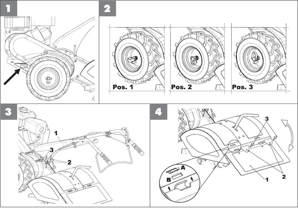
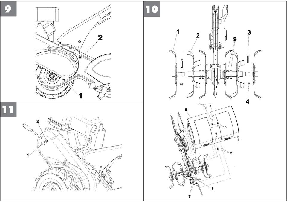
8 ITALIANO 6 Durante il trasporto della macchina e tutte le operazioni di manutenzione, pulitura, cambio degli attrezzi, il motore deve essere spento. 7 Allontanarsi dalla macchina non prima di aver spento il motore. 8 Non avviare la macchina in locali chiusi dove si possono accumulare esalazioni di carbonio. 9 AVVERTENZA La benzina è altamente infiammabile: Non fare il pieno di benzina in locali chiusi né con il motore in moto, non fumare e fare attenzione alle fuoriuscite di combustibile dal serbatoio. In caso di fuoriuscita non tentare di avviare il motore, ma allontanare la macchina dall area interessata evitando di creare fonti di accensione finchè non si sono dissipati i vapori della benzina. Rimettere a posto correttamente i tappi del serbatoio e del contenitore della benzina. 10 Attenzione al tubo di scarico. Le parti vicine possono arrivare a 80. Sostituire i silenziatori usurati o difettosi. 11 Non usare il motocoltivatore su forti pendenze, potrebbe ribaltarsi. Sui pendii lavorare sempre trasversalmente, mai in salita o discesa ed esercitare la massima cautela nei cambi di direzione. 12 Prima di iniziare il lavoro con la macchina procedere ad un controllo visivo e verificare che tutti i sistemi antinfortunistici, di cui essa è dotata, siano perfettamente funzionanti. E severamente vietato escluderli o manometterli. 13 Ogni utilizzo improprio, le riparazioni effettuate da personale non specializzato o l impiego di ricambi non originali, comportano il decadimento della garanzia e il declino di ogni responsabilità della ditta costruttrice. DISPOSITIVO DI SICUREZZA Tutti i motocoltivatori sono dotati di dispositivo antinfortunistico. Detto dispositivo causa il disinnesto della frizione e di conseguenza l arresto della macchina in marcia avanti o marcia indietro, al rilascio della relativa leva di comando; inoltre questo dispositivo evita l inserimento della retromarcia mentre è inserita la marcia avanti. ATTENZIONE: a marcia indietro le frese smettono di girare automaticamente. Dispositivo innesto ruote a tre posizioni: (Fig.2) Il motocoltivatore è dotato di uno speciale dispositivo chiamato FORCELLA A TRE POSIZIONI. Nella posizione 1 (libero) la ruota gira libera sull albero così da permettere gli spostamenti della macchina a motore fermo. Nella posizione 2 (bloccato) la ruota risulta solidale con l albero, diventando motrice, cioè pronta per il lavoro, normalmente la più usata. Nella posizione 3 (semidifferenziale) la ruota ha la possibilità di fare circa un giro libera sull albero, così da permettere inversioni di marcia. ATTENZIONE: Tutti gli interventi sulla forcella a tre posizioni, devono essere eseguiti a motore fermo. MONTAGGIO DEL MOTOCOLTIVATORE Il motocoltivatore viene consegnato a destinazione, salvo accordi diversi, parzialmente smontato e sistemato nel suo imballo. Per rendere il motocoltivatore funzionante bisogna completare il montaggio delle parti smontate osservando la seguente procedura. Montaggio manubrio (Fig.3) Fissare il manubrio (fig. 3 part. 1) al supporto (2) per mezzo delle viti (3) e delle rondelle e dadi (4). Quindi fissare il supporto al telaio avvitando su entrambi i lati le viti e relative rondelle (5 e 6). ATTENZIONE: durante il montaggio del manubrio, i cavi comando marce e acceleratore devono rimanere stesi. 2 Montaggio del cofano fresa (solo per versione con fresa 60 cm.) (Fig. 11) Inserire gli allargamenti (part. 1) all estremità delle frese (2) e fissarli con le viti (3) ed il dado (4). Svitare le nr. 6 viti (5) dalle sedi sul telaio, avendo cura di lasciare parzialmente allentate le viti (6) che fissano i supporti (7) al fine di permettere un più agevole assemblaggio. Quindi posizionare il cofano (8) avendo cura di far combaciare le sue asole con le

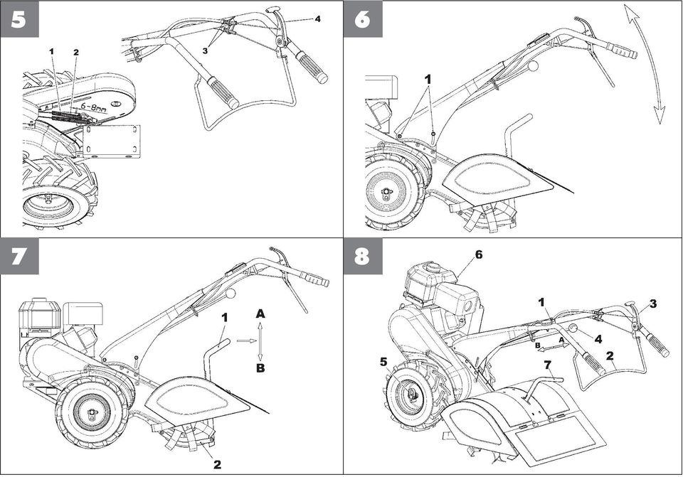
9 Montaggio bandella cofano fresa (Fig.4) Infilare i ganci della bandella (part.1), tenendo questa ruotata verso l alto, nelle relative asole ricavate sul cofano fresa, abbassare la bandella e avvitare le piastrine (2) con le relative viti (3). ATTENZIONE! La bandella deve essere posizionata con i ganci rivolti come nell'ingrandimento in figura, ossia i ganci devono entrare dall'alto nella feritoia "B" ed uscire dalla "A". REGOLAZIONI Registrazione del tendicinghia comando marcia avanti e marcia indietro (Fig.5) Attenzione, le ruote devono iniziare a girare solo quando la leva di comando ha superato la metà della propria corsa. Quando la leva è completamente tirata (posizione di lavoro), la molla di carico del tendicinghia (part.1 marcia avanti) e (part.2 marcia indietro) si deve allungare di circa 6-8 mm. Per ottenere le condizioni sopracitate, occorre agire sul registro (3) installato nelle vicinanze delle relative leve di comando. La trasmissione RM con leva (4) rilasciata, deve avere del gioco sui registri (3). Controllare periodicamente la registrazione delle due trasmissioni, in modo tale da evitare slittamenti delle cinghie ed il conseguente surriscaldamento delle pulegge. Regolazione inclinazione del manubrio (Fig.6) Il manubrio del motocoltivatore è orientabile in altezza. E consigliabile prima di iniziare qualsiasi tipo di lavoro, regolare il manubrio alle esigenze dell operatore per rendere il motocoltivatore facilmente manovrabile, la particolare forma della leva comando marcia avanti permette all operatore di condurre la macchina da destra o da sinistra in modo da non calpestare il terreno già lavorato e di non danneggiare le vegetazione. Allentare le viti di fissaggio supporto manubrio (1). Regolare all altezza ottimale, bloccare le viti (1). Regolazione timone (Fig.7) Per consentire una buona fresatura e un avanzamento regolare del motocoltivatore, la fresa è dotata di timone (part.2) che regola la profondità di lavoro delle zappette. Tirando indietro la leva comando (1) e muovendo la stessa in alto o in basso, si controlla la penetrazione nel terreno: la regolazione è corretta quando la macchina avanza con velocità costante e senza sbalzi. - Fresatura terreni duri: Portare il timone nelle posizione (B). questa posizione corrisponde ad una scarsa profondità di lavorazione. - Fresatura terreni morbidi: Portare il timone nelle posizione (A). questa posizione corrisponde ad una grande profondità di lavorazione. Durante gli spostamenti con la macchina in moto, su superfici diverse dal terreno di lavoro, tenere il timone nella posizione (B), in questo modo si evita alle zappette di scalfire la superficie. ITALIANO DESCRIZIONE DEI COMANDI (Fig.8) 1) Leva comando acceleratore Start-Stop 2) Leva comando marcia avanti. 3) Leva comando marcia indietro. 4) Leva cambio marcia Lenta-Veloce (solo per versione 2+2 velocità) 5) Forcella a tre posizioni 6) Maniglia di avviamento motore. 7) Leva comando sperone. ISTRUZIONI D'USO Dopo le operazioni di montaggio e regolazione il motocoltivatore è pronto per lavorare. ATTENZIONE. Prima di avviare il motore controllare sempre che il motocoltivatore sia in perfette condizioni di funzionamento. - Istruzioni Motore: Leggere attentamente il libretto istruzioni allegato del relativo motore. - Controllare che il filtro aria sia ben pulito. - Riempire il serbatoio di carburante del tipo indicato dalle specifiche nel libretto del motore usando un imbuto con filtro. - Non modificare la taratura del regolatore di velocità di rotazione del motore e non far raggiungere ad esso una condizione di sopravvelocità. - Posizionare la forcella (Fig.2) nella posizione 1 (libero) la ruota gira libera sull albero così da permettere gli spostamenti. - Portarsi ai bordi del terreno da fresare. - Posizionare la forcella (Fig.2) nella posizione 2 (bloccata) posizione di lavoro. 3

10 ITALIANO - Assicurarsi che la leva del cambio(fig.8 part.4 solo versione 2+2 velocità) sia in posizione di folle. - Regolare il manubrio all altezza più adatta al lavoro da eseguire. - Messa in moto del motore (Fig.8) Aprire il rubinetto del carburante (per i motori provvisti), spingere fino a metà la levetta dell acceleratore posto sul manubrio (part.1) se il motore è freddo, azionare il dispositivo di starter sul carburatore, afferrare la maniglia di avviamento e dare uno strappo energico. Avviato il motore riportare, dopo i primi scoppi, lo starter nella posizione di riposo. - Impugnare il manubrio, inserire la marcia (solo per versione 2+2 velocità) pos. A marcia lenta, pos. B marcia veloce. Si consiglia per le prime volte di lavorare in posizione 1 marcia lenta. - Marcia avanti: (Fig.8) tirare la leva frizione (part.2) per tutta la sua corsa, per non danneggiare gli ingranaggi della trasmissione. - Marcia indietro: (Fig.8) lasciare la leva frizione (part.2) e tirare verso di se la leva posta sul manubrio (3), alzando la parte posteriore in modo da fare uscire la fresa dal terreno fino a che la macchina non cominci ad indietreggiare. - Fine lavoro: terminato il lavoro, per arrestare il motore, portare la leva acceleratore (1 Fig.8) nella posizione di minimo o azionare l interruttore di stop sul motore. RIMESSAGGIO E MANUTENZIONE PERIODICA Mantenere serrati tutti i dadi, i bulloni e le viti per garantire il funzionamento della macchina nelle condizioni di sicurezza. Lasciar raffreddare la macchina prima di immagazzinarla e comunque non riporla con benzina nel serbatoio all interno di un edificio, dove i vapori possono raggiungere una fiamma libera o una scintilla. Per ridurre il pericolo di incendio mantenere il motore, il silenziatore e la zona di immagazzinamento della benzina liberi da foglie, erba e grasso in eccesso. Eseguire le operazioni sottoelencate agli intervalli prescritti (per ore si intendono le ore di lavoro della macchina). Scatola cambio (Fig. 9) Controllo livello olio: (Fig.9) Lubrificante: usare olio SAE 80. Verificare il livello dell olio ogni 60 ore: mettere la macchina in piano, svitare il tappo (1) e controllare che l olio sia al margine inferiore del foro, nel caso sia necessario il ripristino del livello rabboccare dal foro del tappo (2), fino a che questo non cominci ad uscire da quello di controllo (1). Riavvitare i tappi. Cambio olio: Sostituire l olio ogni 150 ore. Lo scarico dell olio deve essere effettuato a macchina calda: svitare i tappi (1 e 2), inclinare la macchina per svuotarla completamente, quindi posizionare la macchina in piano, rifornirla di olio dal foro del tappo (2) fino che questo non cominci ad uscire da quello di controllo (1). Riavvitare i tappi. ATTENZIONE. L olio di scarico è un materiale inquinante non disperdere nell ambiente, ma servirsi degli appositi centri di raccolta. Fresa (Fig.10) Ogni qual volta si usa il motocoltivatore, è necessario che l operatore verifichi che le viti e i dadi di fissaggio delle frese sull albero siano serrati a fondo (part.3 e 9). Albero retromarcia (Fig.11) Ogni 50 ore di lavoro ingrassare attraverso l apposito ingrassatore (part. 2) l albero della retromarcia, previo smontaggio del tappo in gomma (1). ATTENZIONE. Una volta terminata l'operazione occorre richiudere il foro col tappo (1), perchè all'interno del carter ci sono organi in movimento. 4 RUMORE AEREO E VIBRAZIONI Valore di pressione acustica al posto di lavoro secondo EN 709 LA e q = 80 db (A). Vibrazione alle stegole secondo EN 709 e ISO Valore rilevato = 7,2 m/s². ACCESSORI - Fresa cm. 32 con coppia ruote in ferro Ø350x50 - Rincalzatore ali fisse con attacco.
 pos. A marcia lenta, pos.")
11 Index Introduction Conditions of use Safety norms Safety device Assembly Adjustments Control system Operating Instructions Garaging & scheduled maintenance Noise level Accessories INTRODUCTION Dear Customer, thank you for the confidence in purchasing our product.we hope you will spend many enjoyable hours using it. The present instructions are issued to ensure a right and correct use of the product : for this reason we beg you to carefully follow such working and safety instructions so that the machine could operate with complete satisfaction and have a long service life. To guarantee what above it is necessary to fit the machine with original components/spare parts. The user/operator forfeits any claims which may arise if the machine is fitted with components other than original spare parts. Subject to changes in design and construction without notice. In order to process customers technical information and spare parts orders, please always state the machine serial number you can see printed on the label placed on the machine left side ( fig. 1). CONDITIONS AND LIMITATIONS OF USE The motor- cultivator is designed and built to hoe the land. The motor- cultivator must only be used with original equipment and spares. Any use other than those here described is prohibited and will involve, in addition to cancellation of the warranty, serious risk for the operator and bystanders. SAFETY PRECAUTIONS & ACCIDENT PREVENTION MEASURES. Both on the machine body and in the present instructions booklet can be found indications and notices linked to the a.m. symbol: in such cases please be careful because you can face potential danger so it is recommended to use a special caution both for operator s own sake and bystanders. WARNING! Before assembly and putting the machine into operation, please read carefully the operating instructions. Persons not familiar with such instructions are not authorized to use the machine. 1 Persons under 16 should not be allowed to use the machine. 2 When operating the machine, the user should ensure that no others, particularly children, are standing in the area. Please, remember that you are responsible for the safe operating of your machine vis-a-vis third persons. 3 Before starting to mill, remove any foreign bodies from the soil. 4 Do not start the machine if standing in front of the rotary cutter, neither get near the machine when working. If pulling the starter short rope, the rotary cutter and the machine have to standstill. 5 During working operations, for protection purposes, it is recommended to wear technical/strong shoes and long trousers. Be careful, because when machine is operating the danger to be wounded in the toes or feet is really high. E N G L I S H 5

12 E N G L I S H 6 During the machine transport and all the maintenance, cleaning, equipment change operations, the engine must be switched off. 7 Before leaving the machine, please switch the engine off. 8 Do not switch the machine on in closed rooms/areas where you can have carbon monoxide exhalations. 9 WARNING!! The petrol/gasoline is highly inflammable: Don t fill the tank neither in closed areas, nor when engine is on, don t smoke and be careful to the petrol/gasoline loss from the tank. In case of leak, don t try to switch the engine on but move the machine away from the area in order to avoid ignition source until the gasoline vapours fade away. Re-place the tank caps and the gasoline box. 10 Keep attention to the exhaust pipe. The parts near the pipe can reach 80 C. Replace the defective and/or worn out silencers Burn hazards!!!. 11 Don t use the motor cultivator on steep slopes: it could overturn!. On slope it is recommended to work crosswise, neither in slope nor in descent and be vary careful during any change of direction. 12 Before putting the machine into operations, check it visually and make sure all the accident prevention measures are working. It is absolutely forbidden to exclude and/or to tamper with them. 13 In case the machine is incorrectly used, and/or the repairs are performed by non-authorized technical staff, and/or fitted by non-original spare parts: any use other than that described above is prohibited and will involve the cancellation of the warranty and the refuse all responsability from the manufacturer. SAFETY DEVICE All the motorcultivators are equipped with an accident prevention device. Such device causes the clutch release and the machine stopping on the single or reverse speed position, to the release of the control lever, furthermore such device avoids the reverse speed insertion if the single speed is on. WARNING! If the machine is on reverse speed the rotavators are automatically stopping. Wheels insertion device on 3 positions : (Fig.2) The motor cultivator is provided with a special device called FORK 3 POSITIONS On position 1 (free) the wheel turns free on the shaft in order to let the machine to move even if the engine is not working; On position 2 (blocked) the wheel is working with the shaft, working as on motion, i.e. ready to start working, such position is the most common used; On position 3 (semi-differential unit) the wheel can perform about a half-turn turning on the shaft, in order to allow turns. WARNING! All the works on the fork must be performed when the engine is stopping. 6 MOTORCULTIVATOR ASSEMBLY The motorcultivator is delivered to destination, partially assembled in its own packaging, unless otherwise agreed. Handlebar assembly (Fig.3) Fix the handlebar (fig. 3 part. 1) to the support (2) using screws (3) washers and nuts (4). Then fix the support to the chassis screwing down the screws and the washers (5 and 6) on both sides. ATTENTION: during the handlebar assembly the speed control and accelerator cables have to be spread out. Rotavators cover assembling (for cultivating width 60 cm. only) (Fig. 11) Insert the expanding parts (part 1) at the bottom of the rotavators (2) and fix them with the screws (3) and the nut (4). Unscrew the 6 pcs. screws (5) on the frame seating. Please be careful about this operation and leave the screws (6) fixing the support (7) slightly turned out in order to allow an easier assembling. Then put the cover (8) in the right position and taking

13 Assembly of the hinge engine hood rotary cutter (Fig.4) put the hinge hooks (part. 1) keeping it turning to the top side into the slots on the engine hood milling, lower the hinge and screw down the plates (2) with the relevant screws (3). ATTENTION! The strap should be placed with the hooks placed as shown in the picture specs. This is to say that the hooks should enter from top to down into the hole B and come our from A position. ADJUSTMENTS Adjustment of the belt stretcher driving wire single speed and reverse (Fig.5) Attention, the wheels have to start working only when the control lever has moved halfway its travel. When the lever is completely pulled (working position), the spring load of the belt stretcher (part. 1 single speed) and (part.2 reverse speed) must extend for 6-8 mm. In order to obtain he a.m. conditions you have to act on the regulator (3) you can see near the drive control lever. The transmission reverse REV. (4) the lever on position released should have some clearance on the registers. Please, carefully check from time to time the adjustement of the two transmissions in order to avoid the belts sliding and the consequent pulleys overheating. Adjustment of the handlebar position (Fig.6) The handlebar position can be height adjusted. Before starting any work it is a good standard operating procedure to adjust the handlebar to the operator s requirements so that the machine could be easily handled. The particular shape of of the single speed control lever allows the operator to drive the machine from the right or the left side in order not to thread on the cultivated ground nor to squash the vegetation. Unscrew down the handlebar support screws (part. 1). Adjust to the suitable/requested position, block the screws (1). Depht adjustment (Fig.7) In order to obtain a good soil cultivation and a smooth machine movement, the cultivators is equipped with a depth setting device (part.2) which regulates the spade working depth. When the depth control lever is pulled is pulled back (1) and moving the same up or down, you can regulated spade penetration into the soil: the adjustment is correct when the machine when the machine moves forward smoothly without lifting out or digging into the soil. - Hard soils cultivation: bring the depth to position (B). such postion corresponds to a small soil penetration. - Soft soils penetration: Bring the depth to position (A). suc position corresponds to a deept soil penetration depth. When moving with the machine working on different surfaces, keep the depth on position (B) in order to avoid the spades to break up the top of the surface. E N G L I S H CONTROLS DESCRIPTION (Fig.8) 1) Accelerator lever control Start-Stop 2) Forward speed lever control. 3) Forward speed lever control 4) Control speed SLOW-FAST (2+2 speed version only) 5) Fork on 3 positions 6) Starter handle 7) Root face control lever. INSTRUCTIONS Following the assembly & adjustment operations the motorcultivator is ready to start working. ATTENTION! Before switching the engine on, carefully check if the motorcultivator is in perfect good conditions. - Engine instructions: Carefully read the istructions booklet anclosed to the relevant engine. - Check if the air filter is clean. - Fill the tank in as per the fuel described in the engine specifications and using a filter filling funnel. - Do not change the calibration of the speeds control rotation device of the engine in order not to over-speed it. - Put the fork (Fig.2) into position 1 (free) so that the wheel could freely turn on the shaft to allow the movements. 7
 Attention, the wheels have to start working only when the control lever has moved halfway its travel.")
14 E N G L I S H - Move the machine to the borders to be milled. - Put the fork (Fig.2) into position 2 (block) working position. - Check if the gearbox control lever (Fig.8 part.4 only 2+2 speed version) is on loose position. - Adjust the handlebar to the requested position/height: - How to switch the engine on (Fig.8): Open the fuel cap (for the engine equipped like this), push to halway the accelerator lever on the handlebar (part.1) if the engine is cold, operate the starte device on the carburettor, bring the starter handle and pull energetically. When the engine is on, after some bursts/bangs, put the starter again at rest position, - Grasp the handlebar, insert the speed (for 2+2 speed version) pos. A slow speed, pos. B fast speed. At the beginning we recommend you to work on position 1, slow speed. - Forward drive: (Fig.8) pull the clutch lever (part.2) to the end of its way, in order not to damage the transmissions gears. - Reverse speed: release the clutch lever (Fig.8) (part.2) and pull towards ourselves the lever on the handlebar (3), to lift up the back part of the machine in order to make the rotavator to come out from the ground until the machines starts to draw back. - At the end of the work: when you finish the work, to stop the engine, bring the accelerator lever (1 Fig.8) to the bottom gear or press the stop switcher on the engine. GARAGING AND SCHEDULED MAINTENANCE Keep attention that all the nuts,screws and bolts are tightened in order to guarantee a good machine working on safety conditions. Leave the machine to cool before garaging anyhow don t room it if the tank still contains some fuel as the vapours could reach some blazes or sparks. To lower the fire danger, keep the engine, the silencer and the fuel area free from leaves, grass or greasy substances. Perform the following operations as per the described intervals. (with the word ìhoursî, we mean the machine working hours). Gearbox (Fig. 9) Oil level control: Use oil SAE 80. Verify the oil level every 60 hours: put the machine on flat surface, remove the cap 1 and check if the oil reaches the hole bottom edge. In case you need to fill it on you have to perform it from the hole of the cap 2. Go on with such operation until you see the oil coming out from control cap 1. Screw both caps again. Oil change: change the oil every 150 hours. The oil drain has to be performed when the machine is hot: remove caps 1, and 2 and tilt the machine to a complete emptying, then put the machine on flat land, fill it in with oil through the hole of cap 2 until the oil starts coming out from control cap 1. Screw both caps again. ATTENTION! Waste fuel oil is a polluting material: don t waste it in the sorroundings, please apply to suitable waste material centres. Cultivator (Fig.10) Every time the motorcultivator is used, it is necessary that the operator controls if the screws ad the fixing nuts of the spades on the shaft are tightened all the way home (part.3 and 9). Reverse speed shaft (Fig.11) Every 50 working hours, grease the reverse speed shaft with the suitable greaser (1), upon disassembling of rubber cap (1). KEEP ATTENTION! once such operation has finished you must close the hole again with the rubber cap (1) because inside the casing there are some gears/parts on motion. 8 NOISE LEVEL AND VIBRATION LEVEL Noise level when working according to EN 709 LA e q = 80 db (A). Handlebar vibration according to EN 709 e ISO Detected level = 7,2 m/s². ACCESSORIES - 32 cm. rotary cultivator equipped with pair iron wheels Ø350x50 - Fixed-wing ridger with coupling.
 if the engine is cold, operate the starte device on the carburettor, bring the starter handle and pull energetically.")
15 Inhaltsverzeichnis Einleitung Einsatzbedingungen Sicherheitsbestimmungen Sicherheitsvorrichtung Montage Einstellungen Beschreibung der Bedienelemente Betriebsanleitung Lagerhaltung und laufende Wartung Lärmpegel Zubehörteile EINLEITUNG Sehr geehrter Kunde, wir danken Ihnen für das Vertrauen, das Sie unserem Produkt geschenkt haben. Wir wünschen Ihnen eine angenehme und sichere Benutzung dieser Maschine. Dieses Handbuch enthält alle Informationen für einen korrekten und problemlosen Gebrauch. Daher empfehlen wir Ihnen, die auf den folgenden Seiten stehenden SICHERHEITSBESTIMMUNGEN und GEBRAUCHSANLEITUNGEN aufmerksam zu lesen, damit Sie die Maschine auf lange Zeit störungsfrei und sicher benutzen können. Um dies zu gewährleisten, ist es erforderlich, ausschließlich Originalersatzteile zu verwenden. Der Anwender verliert jeden Anspruch auf Garantie, wenn er Ersatzteile verwendet, die kein Original sind. Konstruktionsänderungen sind vorbehalten. Für Informationen und zum Bestellen von Ersatzteilen geben Sie bitte immer die Artikel-Nr. an, bei den etwaigen Anforderungen des Kundendienstes oder beim Bestellen von Ersatzteilen ist immer die Seriennummer der fraglichen Maschine anzugeben, wobei diese Daten auf dem Typenschild abzulesen sind, das sich auf der linken Seite der Maschine befindet. (Abb. 1) EINSATZBEDINGUNGEN - EINSATZGRENZEN Der Einachsschlepper ist zur Ausführung von Hackarbeit. Der Einachsschlepper darf nur mit Original-Zusatzgeräten und Original-Ersatzteilen arbeiten. Jede Benutzung, die von der hier beschriebenen abweicht, ist nicht gestattet. Es führt nicht nur zum Verfall der Garantiegewährung, sondern stellt auch eine große Gefahr für den Bediener und alle Personen die sich in Reichweite der Maschine befinden dar. SICHERHEITS- UND UNFALLVERHÜTUNGSBESTIMMUNGEN Auf der Maschine und in diesem Handbuch stehen einige Meldungen und Angaben, die von diesem Signal begleitet werden. Sie geben das Vorhandensein einer potentiellen Gefahr an, so dass es angemessen ist, der eigenen Sicherheit und der Sicherheit derer wegen, die sich in der Reichweite der Maschine befinden könnten, eine besondere Vorsicht walten zu lassen. Achtung: Vor der Montage und der Inbetriebnahme unbedingt die Betriebsanleitung aufmerksam durchlesen. Personen, welche die Bestimmungen zur Benutzung nicht kennen, dürfen die Maschine nicht verwenden. 1 Jugendlichen unter 16 Jahren ist der Gebrauch zu verbieten. 2 Sicherstellen, dass keine Kinder in der Nähe sind. Sie sind für die Schäden verantwortlich, die Dritten entstehen. 3 Bevor man mit dem Fräsen beginnt, Fremdkörper im Boden entfernen. 4 Die Maschine nicht in Betrieb nehmen, wenn man vor der Fräse steht. Nähern Sie sich dieser nicht, wenn sie läuft. Wenn man die Zündschnur des Motors zieht, dürfen die Maschine und die Fräse sich noch nicht bewegen. 5 Während der Arbeit sollte man zum besseren Schutz festes Schuhwerk und lange Hosen tragen. Vorsichtig vorgehen, weil eine große Gefahr besteht, sich bei laufender Maschine die Finger oder die Füße zu verletzen. D E U T S C H 9

16 D E U T S C H 6 Während des Transports der Maschine und aller Wartungsarbeiten, dem Reinigen und dem Wechsel der Geräte muss der Motor immer abgeschaltet sein. 7 Entfernen Sie sich erst dann von der Maschine, wenn man den Motor abgeschaltet hat. 8 Die Maschine nicht in geschlossenen Räumen laufen lassen, wo die entstehenden Abgase sich anhäufen könnten. 9 HINWEIS Benzin ist ein feuergefährlicher Stoff: Nicht in geschlossenen Räumen und nicht bei laufendem Motor tanken, nicht rauchen und auf den aus dem Tank auslaufenden Treibstoff achten. Bei auslaufendem Treibstoff nicht versuchen, den Motor zu starten, sondern die Maschine von der betroffenen Stelle entfernen und vermeiden, Zündquellen zu erzeugen, bis die Benzindämpfe nicht abgezogen sind. Die Stopfen des Tanks und des Benzinbehälters wieder ordentlich aufschrauben. 10 Auf das Auspuffrohr achten. Die nahe am Auspuff liegenden Teile können bis zu 80 heiß werden. Verschlissene oder defekte Auspufftöpfe ersetzen. 11 Den Einachsschlepper nicht auf Gelände mit starkem Gefälle benutzen: Er könnte umkippen. Auf Gefälle sollte man immer in der Querrichtung arbeiten, nie bergauf oder bergab. Beim Gangschalten sehr vorsichtig vorgehen. 12 Bevor man die Arbeit mit der Maschine beginnt, eine Sichtprüfung vornehmen und sicherstellen, dass alle Unfallschutzvorkehrungen, mit denen sie versehen ist, vollkommen funktionstüchtig sind. Es ist streng verboten, diese zu umgehen oder zu manipulieren. 13 Jede bestimmungswidrige Benutzung, nicht vom Fachmann vorgenommene Reparaturen oder die Benutzung von Ersatzteilen, die kein Original sind, führen zum Verfall der Garantie und dem Verlust der Herstellerhaftung. SICHERHEITSVORRICHTUNGEN Alle Einachsschlepper sind mit einer Unfallverhütungsvorrichtung ausgestattet. Diese Vorrichtung führt zum Ausschalten der Kupplung und folglich zum Anhalten der Maschine beim Vorwärts- oder Rückwärtsfahren, wenn man den entsprechenden Schalthebel loslässt; außerdem verhindert dieser Vorrichtung das Einschalten des Rückwärtsgangs, während der Vorwärtsgang eingeschaltet ist. ACHTUNG. Wenn der Rückwärtsgang eingeschaltet wird, kommen die Fräsen automatisch zum Stehen. Vorrichtung zum Radeinrasten mit drei Positionen: (Abb. 2) Der Einachsschlepper ist mit einer speziellen Vorrichtung ausgestattet, die wir GABEL MIT DREI POSITIONEN nennen. In der Position 1 (frei) dreht sich das Rad frei auf der Welle, damit die Maschine bei stehenden Motor bewegt werden kann. In der Position 2 (blockiert) dreht sich das Rad zusammen mit der Welle, wobei es Triebrad wird, d.h. betriebsbereit, in der Regel die am häufigsten benutzte Position. In der Position 3 (Halbdifferential) hat das Rad die Möglichkeit, circa eine freie Umdrehung auf der Welle auszuführen, damit die Umkehr der Fahrtrichtung möglich ist. ACHTUNG! Alle Eingriffe auf der Gabel mit drei Positionen müssen bei stehendem Motor ausgeführt werden. 10 MONTAGE DES EINACHSSCHLEPPERS Der Einachsschlepper wird, wenn nichts anderes vereinbart worden ist, am Bestimmungsort zerlegt und in seiner Verpackung ausgeliefert. Um den Einachsschlepper benutzen zu können, ist die Montage der abgebauten Teile vorzunehmen, wobei die folgende Prozedur zu beachten ist. Montage des Lenkholms (Abb. 3) Den Lenkholm (Teil 1) am Träger (2) befestigen. Dazu die Schrauben (3) und Unterlegscheiben (4) benutzen, die auf beiden Seiten vorhanden sind. Achtung: Während der Montage des Lenkholms müssen die Kabel der Gangschaltung und des Gashebels gespannt bleiben. Montage der Fräsenhaube (nur für Hacksatz cm. 60) (Abb. 11) Die Hacksatzverbreiterungen (Teil 1) in die Hackfräsenenden (2) einstecken, durch die Schrauben (3) und die Mutter (4) befestigen. Die Nr.6 Schrauben (5) ab den Gehäusesitzen abbschrauben. Bei diesem Vorgang ist es nötig, die Schrauben (6), die Halter (7) befestigen, locker lassen, damit eine leichtere Montage zu bekommen. Daher die Haube (8) positionieren,

17 damit die Ösen mit den Schraubensitzen genau übereinstimmen, dann die Nr.6 Schrauben (5) wieder einschrauben. Endlich auch die Schrauben (6) der Halter (7) sorgfältig befestigen. Montage des Prallblechs der Fräsenhaube (Abb. 4) Die Haken des Prallblechs (Teil 1) nach oben gedreht halten und sie in die Langlöcher einstecken, die auf der Fräsenhaube vorhanden sind, das Prallblech senken und die Befestigungsschrauben (2) anziehen. ACHTUNG! Das Prallblech muss mit den Haken, wie die Vergrößerung im Bild gewandt, gestellt werden sein, das heißt die Haken von oben in den Schlitz B hinein gehen und aus A hinausgehen müssen. EINSTELLUNGEN Einstellung des Riemenspanners zum Vorwärts- und Rückwärtsfahren: (Abb. 5) Achtung: Die Räder dürfen erst dann anfangen, sich zu drehen, wenn der Schalthebel schon über die Hälfte seines Schaltweges zurückgelegt hat. Wenn der Schalthebel ganz gezogen ist (Arbeitsposition), muss sich die Ladefeder des Riemenspanners (Teil 1 Vorwärtsfahren) und (2 Rückwärtsfahren) um circa 6-8 mm verlängern. Um diesen Zustand zu erhalten, ist die Einstellvorrichtung (3) zu benutzen, die in der Nähe der Schalthebel vorhanden ist. Das Rückwärtsgangskabel mit dem wieder gelassenen Schalthebel (4), muss Spielraum über die Einstellvorrichtungen (3) haben. Die Einstellung der 2 Züge periodisch kontrollieren, sodass das Schittern des Riemens und die folgende Überhitzung der Riemenscheiben zu vermeiden. Einstellung der Lenkholmneigung: (Abb. 6) Der Lenkholm des Einachsschleppers ist höherverstellbar. Bevor man irgendeine Arbeit beginnt, sollte man den Lenkholm aufgrund der Erfordernisse des Bedieners einstellen, damit der Einachsschlepper leicht manövrierbar ist. Die besondere Form des Schalthebels zum Vorwärtsfahren gestattet es dem Bediener, die Maschine von rechts oder links zu führen, damit er das schon bearbeitete Gelände nicht mehr betreten muss und die Pflanzen nicht beschädigt. Die Befestigungsschrauben des Lenkholmträgers Teil 1 lockern. Die optimale Höhe einstellen, dann mit den Schrauben das Teil 1 blockieren. Deichseleinstellung: (Abb. 7) Um eine gute Fräsarbeit auszuführen und damit der Einachsschlepper regelmäßig vorwärts fährt, ist die Fräse mit einer Deichsel (Teil 2) ausgestattet, mit der die Arbeitstiefe der Fräswerkzeuge eingestellt werden kann. Wenn man die Schalthebel (1) zurückzieht und ihn nach oben oder unten bewegt, regelt man die Eindringtiefe in den Boden: Die Einstellung ist korrekt, wenn die Maschine ruckfrei und mit konstanter Geschwindigkeit vorwärts läuft. - Fräsen auf hartem Boden: Die Deichsel in die Position (B) bringen. Diese Position entspricht einer geringeren Arbeitstiefe. - Fräsen auf weichem Boden: Die Deichsel in die Position (A) bringen. Diese Position entspricht einer großen Arbeitstiefe. Während des Bewegens mit laufender Maschine auf Oberflächen, bei denen der Boden nicht zu bearbeiten ist, die Deichsel in der Position (B) halten, damit die Fräswerkzeuge nicht den Boden berühren. D E U T S C H BESCHREIBUNG DER BEDIENELEMENTE (Abb. 8) 1) Gasschalthebel Start-Stop 2) Schalthebel für Vorwärtsfahren 3) Schalhebel für Rückwärtsfahren 4) Schalthebel für Langsam/Schnell (nur für die Mod. 1vg+1rg) 5) Gabel mit drei Positionen 6) Griff zum Motoranlassen 7) Schalthebel für den Sporn. BETRIEBSANLEITUNGEN Nach der Montage und der Ausführung der Einstellungen ist der Einachsschlepper bereit, seine Arbeit aufzunehmen. ACHTUNG Vor dem Starten des Motors immer sicherstellen, dass der Einachsschlepper einen einwandfreien Betriebszustand aufweist. - Anweisungen für den Motor: Lesen Sie aufmerksam die Betriebsanleitung durch, die den Motor beiliegt. - Sicherstellen, dass der Luftfilter sauber ist. - Den Kraftstofftank mit dem Treibstoff füllen, der in den Angaben der Betriebsanleitung des Motors steht. Zum Einfüllen einen Trichter mit Filter benutzen. - Die Einstellung des Drehzahlreglers des Motors nicht ändern. Der Motor darf keine Übergeschwindigkeit erreichen. 11

18 D E U T S C H - Die Gabel (Abb. 2) auf die Position 1 (frei) stellen. Das Rad dreht sich dann frei auf der Welle und man kann die Maschine bequem verfahren. - Fahren Sie die Maschine an den Rand des zu fräsenden Bodens. - Die Gabel (Abb. 2) in die Position 2 (blockiert), d.h. die Arbeitsposition bringen. - Sicherstellen, dass der Gangschalthebel (Abb. 8 Teil 4, nur in der Mod. 2vg+2rg) sich in der neutralen Stellung befindet. - Den Lenkholm auf die Höhe stellen, die am besten zu der auszuführenden Arbeit passt. - Anlassen des Motors (Abb. 8) Den Kraftstoffhahn (bei den Motoren, die damit ausgerüstet sind) öffnen. Den Gasschalthebel auf dem Lenkholm (Teil 1) auf die Position von Standgas bringen. Wenn der Motor kalt ist, den Starter auf dem Vergaser betätigen, den Startgriff in die Hand nehmen und kräftig daran ziehen. Wenn der Motor gestartet ist, den Starter wieder in die Ruhestellung bringen. - Den Lenkholm in die Hände nehmen, den Gang einlegen (für Mod. 2vg+2rg) Pos. A langsames Fahren, Pos. B schnelles Fahren. Bei den ersten Versuchen, mit der Maschine zu arbeiten, sollte man den Hebel in der Position 1 langsames Fahren benutzen. - Fahrantrieb vorwärts: (Abb. 8) den Kupplungshebel (Teil 2) ganz herausziehen, um die Antriebszahnräder nicht zu beschädigen. - Rückwärtsfahren: Den Kupplungshebel Teil 2 (Abb. 8) loslassen und den Hebel auf dem Lenkholm (Teil 3) auf sich zu ziehen, wobei man den hinteren Teil hochzieht, damit die Fräse aus dem Boden austritt, bis die Maschine beginnt, rückwärts zu fahren. - Ende der Arbeit: Am Ende der Arbeit zum Abstellen des Motors den Gasschalthebel (1 Fig.8) in die Position für Standgas bringen oder den Stop- Schalter auf dem Motor betätigen. LAGERHALTUNG UND LAUFENDE WARTUNG Alle Muttern, Bolzen und Schrauben angezogen halten, um den sicheren Betrieb der Maschine zu gewährleisten. Die Maschine abkühlen lassen, bevor man sie auf Lager stellt und auf keinen Fall Benzin in den Tank füllen, wenn man sie in einem Gebäude abstellt, weil die Dämpfe eine freie Flamme oder Funken erreichen könnten. Um Brandgefahr zu vermeiden, den Motor, den Auspufftopf und den Lagerhaltungsbereich für das Benzin frei von Laub, Gras oder zu viel Fett halten. Die untenstehend angeführten Vorgänge zu den vorgeschriebenen Zeitabständen ausführen (unter Stunden verstehen wir die Betriebsstunden der Maschine). Getriebegehäuse (Abb. 9) Prüfung des Ölstands Schmierstoff: Verwenden Sie Öl SAE 80. Prüfen Sie den Ölstand alle 60 Stunden: Stellen Sie die Maschine auf eine ebene Fläche, schrauben den Stopfen 1 an und prüfen, dass das Öl unterhalb der unteren Lochkante steht. Falls Ö nachgefüllt werden muss, ist das Ö durch die Öffnung von Stopfen 2 einzufüllen, bis das Öl aus der Öffnung 1 austritt. Die Stopfen wieder aufschrauben. Ölwechsel: Das Öl alle 150 Stunden wechseln. Um das Öl zu wechseln, muss die Maschine warm sein. Dann die Schrauben 1 und 2 abschrauben, die Maschine schräg stellen, um das Öl ganz auslaufen zu lassen. Die Maschine dann wieder auf eine ebene Fläche stellen, durch die Öffnung von Stopfen 2 Öl einfüllen, bis das Öl durch die Öffnung von Stopfen 1 austritt. Die Stopfen dann wieder aufschrauben. Achtung. Das auslaufende Öl ist ein Schadstoff, der nicht in die Umwelt gelangen darf, sondern den Sammelstellen für Altöl zuzuführen ist. Fräse (Abb. 10) Jedes Mal, wenn man den Einachsschlepper benutzt, muss der Bediener prüfen, dass die Schrauben und Befestigungsmuttern der Fräsen auf der Welle fest angezogen sind (Teil 3 und 9). Welle Rückwärtsfahren (Abb. 11) Alle 50 Betriebsstunden die Welle für Rückwärtsfahren mit dem Schmiernippel (Teil 1) schmieren, nach der Demontage des Gummistöpsels (1). ACHTUNG: nachdem dieser Vorgang beendet ist, muss man das Loch durch Stöpsel wiederschliessen, da es bewegliche Teile auf der Innenseite des Gehäuses gibt. 12 LÄRMPEGEL UND VIBRATIONEN Schalldruckwert am Arbeitsplatz nach EN 709 LA eq = 80 db (A). Vibrationen am Lenkholm nach EN 709 und ISO Messwert = 7,2 m/s². ZUBEHÖRTEILE - Hacksatz cm.32 mit Eisenräder Ø350x50 - Häufelkörper mit ortsfesten Flügeln mit Anschluss.
 Den Kraftstoffhahn (bei den Motoren, die damit ausgerüstet sind) öffnen. Den Gasschalthebel auf dem Lenkholm (Teil 1) auf die Position von Standgas bringen.")
19 Table des matières Introduction Conditions d'utilisation Règles de sécurité Dispositif de sécurité Montage Réglages D e s c r i p t i o n commandes Mode díemploi d e s Entreposage et entretien périodique Bruit aérien Accessoires INTRODUCTION Cher client, nous vous remercions de la confiance que vous avez bien voulu accorder à notre produit et vous en souhaitons une agréable utilisation. Cette notice contient toutes les informations pour vous permettre d utiliser correctement et facilement votre machine; nous vous conseillons donc de lire attentivement les NORMES DE SÉCURITÉ et le MODE D EMPLOI ci-dessous rapportés pour un fonctionnement sans inconvénients et durable. Pour que ces conditions soient garanties, il est nécessaire de n utiliser que des pièces de rechange d origine. L utilisateur perd tous ses droits à la garantie en cas d utilisation de pièces de rechange n étant pas d origine. Sous réserve de modifications techniques et de fabrication. Pour toutes questions ou commandes concernant les pièces de rechange, nous vous prions de bien vouloir indiquer le numéro de l article correspondant; pour toute demande d Assistance Technique ou commande de pièces de rechange, nous vous prions de toujours indiquer le numéro de matricule de la machine concernée, en relevant les données rapportées sur l étiquette d identification placée sur le côté gauche de la machine (Fig. 1). CONDITIONS D'UTILISATION - LIMITES D'EMPLOI Le motoculteur est conçue et construite pour effectuer des opérations de binage du sol et il ne peut travailler exclusivement qu'avec des outils et des pièces de rechange d'origine. Toute utilisation différente de celle préconisée est illégale et entraîne l'annulation de la garantie, mais représente aussi un danger grave pour l'opérateur et les personnes exposées. RÈGLES DE SÉCURITÉ ET CONTRE LES ACCIDENTS DU TRAVAIL Sur la machine et à l intérieur de cette notice sont présentes des inscriptions et des indications suivies de ce signal dont le but est d indiquer la présence d un danger potentiel: il est par conséquent opportun d agir avec prudence afin de garantir sa propre sécurité et celle des personnes éventuellement présentes dans le rayon d action de la machine. Attention : lire attentivement le manuel d instruction avant de procéder au montage et à la mise en service de la machine. Cette dernière ne doit être utilisée que par des personnes qui en connaissent le mode d emploi. 1 Interdire l emploi de la machine aux personnes de moins de 16 ans. 2 Veiller à ce qu aucun enfant ne se trouve à proximité. N oubliez pas que vous êtes responsables des dommages éventuels causés à des tiers. 3 Débarrasser le terrain au maximum de ses déchets avant de commencer les opérations de binage. 4 Ne pas mettre en marche la machine lorsqu on se trouve devant la fraise et ne pas s y approcher lorsqu elle est en marche. Lorsqu on tire sur la corde du lanceur, les fraises et la machine ne doivent pas se mettre en marche. FRANÇAIS 13

20 FRANÇAIS 5 Pour bénéficier d une meilleure protection durant le travail, il est nécessaire de porter des chaussures robustes et un pantalon long. Faire particulièrement attention dans la mesure où les risques de blessures aux doigts ou aux pieds sont très élevés lorsque la machine est en marche. 6 Durant le transport de la machine et toutes les opérations d entretien, de nettoyage ou de changement d outils, le moteur doit être à l arrêt. 7 Ne jamais s éloigner de la machine avant d en avoir éteint le moteur. 8 Ne pas jamais mettre en route la machine dans des locaux clos dans lesquels pourraient s accumuler des émanations de carbone. 9 MISE EN GARDE L essence est hautement inflammable:ne pas faire le plein d essence dans des locaux clos et lorsque le moteur est en marche; ne pas fumer ; veiller à ce que le combustible ne déborde du réservoir. En cas de débordement, ne pas tenter de mettre en route le moteur, mais éloigner la machine de la zone concernée en évitant de créer des sources d inflammation jusqu à ce que les vapeurs d essence se soient dissipées. Remettre correctement en place les bouchons du réservoir et du récipient contenant l essence. 10 Attention au pot d échappement. Les parties avoisinantes peuvent atteindre des températures proches de 80 C. Remplacer les silencieux usés ou défectueux. 11 Ne pas utiliser le motoculteur en présence de pentes raides car il pourrait se retourner. Le travail en pente doit toujours se faire de travers, jamais en montée ni en descente ; prêter une extrême attention aux changements de direction. 12 Avant de commencer le travail, effectuer un contrôle visuel de la machine pour vérifier si tous les systèmes contre les accidents du travail dont elle est équipée fonctionnent parfaitement. Il est formellement interdit de les ôter ou de les altérer. 13 Une utilisation impropre, des réparations défectueuses effectuées par un personnel non spécialisé, ou l emploi de pièces de rechanges n étant pas d origine entraînent l expiration de la garantie et exonèrent le constructeur de toute responsabilité. DISPOSITIF DE SÉCURITÉ Tous les motoculteurs sont pourvus d un dispositif contre les accidents. Celui-ci provoque le désembrayage de la transmission et, en conséquence, l arrêt de la machine en marche avant ou en marche arrière quand on relâche le levier de commande; en outre, ce dispositif interdit toute introduction de la marche arrière lorsque la marche avant est introduite. Attention, les fraises cessent automatiquement de tourner lorsque la machine est en marche arrière. Dispositif d embrayage des roues à trois positions: (Fig. 2). Le motoculteur est équipé d un dispositif spécial appelé FOUR- CHETTE À TROIS POSITIONS. Sur la position 1 (libre), la roue tourne librement autour de l arbre de façon à permettre à la machine de se déplacer lorsque le moteur est à l arrêt. Sur la position 2 (bloqué), la roue est solidaire de l arbre et devient motrice (prête pour le travail) : solution habituellement la plus utilisée. Sur la position 3 (semi-différentiel), la roue a la possibilité d accomplir à peu près un tour libre autour de l arbre, de façon à pouvoir effectuer des demitours. ATTENTION Toutes les interventions sur la fourchette à trois position doivent être effectuées lorsque le moteur est à l arrêt. 14 MONTAGE DU MOTOCULTEUR Sauf accord contraire, le motoculteur est livré à destination partiellement démonté et emballé. Pour que le motoculteur puisse fonctionner, il est nécessaire de compléter le montage des parties désassemblées en respectant la procédure suivante: Montage du mancheron (Fig. 3) Fixer le mancheron (fig. 3 détail 1) au support (2) à l aide des vis (3), des rondelles et des écrous (4). Puis, fixez le support au châssis en vissant, sur les deux côtés, les vis avec leurs rondelles (5 et 6). Attention: durant le montage du mancheron, les câbles de commande des vitesses et de l accélérateur doivent rester détendus. Montage du capot fraise (seulement pour le model avec fraise 60 cm.) (Fig. 11) Inserér les élargissements (part. 1) au bout des fraises (2) et fixer les avec les vis (3) et l ècrou. Dèvisser les 6 vis (5) du siége du cadre: faites attention que les vis (6) fixant les supports soient partiellement desserer au but de permettre un montage plus facile. Après mettre le capot (8) et joindre les trous avec les sièges des vis et visser de nouveau les 6 vis (5). Enfin fixer avec attention les vis (6) des supports (7) même.

Tipologie installative - Installation types Type d installation - Installationstypen Tipos de instalación - Τυπολογίες εγκατάστασης
 AMPADE MOOCROMATICHE VIMAR DIMMERABII A 0 V~ - VIMAR 0 V~ DIMMABE MOOCHROME AMP AMPE MOOCHROME VIMAR VARIATEUR 0 V~ - DIMMERFÄHIGE MOOCHROMATICHE AMPE VO VIMAR MIT 0 V~ ÁMPARA MOOCROMÁTICA VIMAR REGUABE
English PDFsharp is a.net library for creating and processing PDF documents 'on the fly'. The library is completely written in C# and based
 English PDFsharp is a.net library for creating and processing PDF documents 'on the fly'. The library is completely written in C# and based exclusively on safe, managed code. PDFsharp offers two powerful
[1] P Q. Fig. 3.1
![[1] P Q. Fig. 3.1](/thumbs/79/80362156.jpg "[1] P Q. Fig. 3.1") 1 (a) Define resistance....... [1] (b) The smallest conductor within a computer processing chip can be represented as a rectangular block that is one atom high, four atoms wide and twenty atoms long. One
1 (a) Define resistance....... [1] (b) The smallest conductor within a computer processing chip can be represented as a rectangular block that is one atom high, four atoms wide and twenty atoms long. One
Tipologie installative - Installation types Types d installation - Die einbauanweisungen Tipos de instalación - Τυπολογίες εγκατάστασης
 Types d installation Die einbauanweisungen Tipos de instalación Τυπολογίες εγκατάστασης AMPADE MOOCROMATICHE VIMAR DIMMERABII A 0 V~ MOOCHROME DIMMABE AMP VIMAR 0 V~ AMPE MOOCHROME VIMAR DIMMABE 0 V~ EUCHTE
Right Rear Door. Let's now finish the door hinge saga with the right rear door
 Right Rear Door Let's now finish the door hinge saga with the right rear door You may have been already guessed my steps, so there is not much to describe in detail. Old upper one file:///c /Documents
(REV:01) RYOBI 48 Volt Lawn Mower Model No. RY14110 Replacement Parts List
 RYOBI 48 Volt Lawn Mower Model No. RY14110 Replacement Parts List") 9800-86 2-0-0 (REV:0) RYOBI 48 Volt Lawn Mower Model No. RY0 Replacement Parts List RYOBI RY0 48 volt lawn mower 3 38 39 44 39 36 34 36 42 38 39 3 4 37 34 3 43 2 32 0 8 9 2 4 33 8 7 6 3 6 7 22 8 20 3 30
9800-86 2-0-0 (REV:0) RYOBI 48 Volt Lawn Mower Model No. RY0 Replacement Parts List RYOBI RY0 48 volt lawn mower 3 38 39 44 39 36 34 36 42 38 39 3 4 37 34 3 43 2 32 0 8 9 2 4 33 8 7 6 3 6 7 22 8 20 3 30
(REV:01) RYOBI 48 Volt Lawn Mower Model No. RY14110A Replacement Parts List
 RYOBI 48 Volt Lawn Mower Model No. RY14110A Replacement Parts List") 9000-7 9-- (REV:0) RYOBI 4 Volt Lawn Mower Model No. RY0A Replacement Parts List RYOBI RY0A 4 VOLT LAWN MOWER 3 3 39 44 39 3 34 3 42 3 39 3 4 37 34 3 43 2 0 37 2 33 32 3 9 7 22 30 4 7 3 20 9 3 2 2 27 2
9000-7 9-- (REV:0) RYOBI 4 Volt Lawn Mower Model No. RY0A Replacement Parts List RYOBI RY0A 4 VOLT LAWN MOWER 3 3 39 44 39 3 34 3 42 3 39 3 4 37 34 3 43 2 0 37 2 33 32 3 9 7 22 30 4 7 3 20 9 3 2 2 27 2
4K HDMI Splitter 1x4. User s Guide / Bedienungsanleitung / Εγχειρίδιο Χρήστη
 4K HDMI Splitter 1x4 User s Guide / Bedienungsanleitung / Εγχειρίδιο Χρήστη INTRODUCTION The EDISION 4K HDMI Splitter 1x4 uses a single HDMI input source, to distribute it to 4 HDMI outputs. The splitter
Door Hinge replacement (Rear Left Door)
") Door Hinge replacement (Rear Left Door) We will continue the previous article by replacing the hinges of the rear left hand side door. I will use again the same procedure and means I employed during the
Door Hinge replacement (Rear Left Door) We will continue the previous article by replacing the hinges of the rear left hand side door. I will use again the same procedure and means I employed during the
Advanced Subsidiary Unit 1: Understanding and Written Response
 Write your name here Surname Other names Edexcel GE entre Number andidate Number Greek dvanced Subsidiary Unit 1: Understanding and Written Response Thursday 16 May 2013 Morning Time: 2 hours 45 minutes
Parts catalogue LAWN MOWER
 OREC ISSUED NO. GR535PRO-1 Parts catalogue LAWN MOWER (EXPORT MODEL) GR535PRO(2Action) MODEL GR535PRO CODE 0278- CONTENTS Fig.1 GEAR CASE------------------------------------------------------------ 1 Fig.2
derivation of the Laplacian from rectangular to spherical coordinates
 derivation of the Laplacian from rectangular to spherical coordinates swapnizzle 03-03- :5:43 We begin by recognizing the familiar conversion from rectangular to spherical coordinates (note that φ is used
MOTORI PER VENTILATORI MOTORS FOR BLOWERS
 MOTORI PER VENTILATORI MOTORS FOR BLOWERS LR 91167 FLANGIA TIPO A FLANGE TYPE A TIPO / TYPE A B C D E F G H I* L M N O P Q BM.80.A2.1000 315 250 290 20 225 φ 7 155 33 19 h7 114 84 6 21.5 M 8 3/8 BM.80.A2.1001
MSN DESK TOP ENCLOSURE WITH STAND / CARRYING HANDLE
 MSN SERIES MSN DESK TOP ENCLOSURE WITH STAND / CARRYING HANDLE W H FEATURE Available in 176 sizes. Stand / carrying handle can be adjusted in 30 degree. Maximum load is kg. There are no ventilation hole
the total number of electrons passing through the lamp.
 1. A 12 V 36 W lamp is lit to normal brightness using a 12 V car battery of negligible internal resistance. The lamp is switched on for one hour (3600 s). For the time of 1 hour, calculate (i) the energy
MS SERIES MS DESK TOP ENCLOSURE APPLICATION EXAMPLE FEATURE. Measuring instruments. Power supply equipments
 MS SERIES MS DESK TOP ENCLOSURE FEATURE Available in 176 sizes. Screws are not appeared on the surface. Usable as rack mount case with optinal mounting bracket. There are no ventilation hole for cover
Περιεχόμενα / Contents
 Aερόθερμo / Fan Heater PTC-906 Περιεχόμενα / Contents GR... Σελίδες 3-8 EN... Pages 9-11 2 GR Ευχαριστούμε που επιλέξατε μια συσκευή της γκάμας θερμαντικών IZZY. Σημαντικές Οδηγίες Ασφαλείας Τα Μέρη της
ΟΔΗΓΙΕΣ ΣΥΝΑΡΜΟΛΟΓΗΣΗΣ/ ASSEMBLY INSTRUCTION ΤΟΜΜΥ ΚΡΕΒΑΤΙ/BED
 ΟΔΗΓΙΕΣ ΣΥΝΑΡΜΟΛΟΓΗΣΗΣ/ ASSEMBLY INSTRUCTION ΤΟΜΜΥ ΚΡΕΒΑΤΙ/BED 1. Παρακαλώ πολύ διαβάστε προσεκτικά τις οδηγίες πριν την συναρμολόγηση/ Please read the instructions carefully. 2. Παρακαλώ πολύ όπως ελέγξτε
La Déduction naturelle
 La Déduction naturelle Pierre Lescanne 14 février 2007 13 : 54 Qu est-ce que la déduction naturelle? En déduction naturelle, on raisonne avec des hypothèses. Qu est-ce que la déduction naturelle? En déduction
User s Manual / Οδηγίες Χρήσης
 User s Manual / Οδηγίες Χρήσης EUROPEAN STANDARDS Your child s safety depends on you. Proper bed rail usage cannot be assured unless you follow these instructions. DO NOT USE YOUR BED RAIL UNTILL YOU READ
HOMEWORK 4 = G. In order to plot the stress versus the stretch we define a normalized stretch:
 HOMEWORK 4 Problem a For the fast loading case, we want to derive the relationship between P zz and λ z. We know that the nominal stress is expressed as: P zz = ψ λ z where λ z = λ λ z. Therefore, applying
ΕΣΩΤΕΡΙΚΗ ΜΟΝΑΔΑ ΚΛΙΜΑΤΙΣΤΙΚΟ ΔΙΑΙΡΟΥΜΕΝΟΥ ΤΥΠΟΥ ΜΟΝΤΕΛΟ RAD-18RPA RAD-25RPA RAD-35RPA RAD-50RPA. Eλληνικά ΕΣΩΤΕΡΙΚΗ ΜΟΝΑΔΑ
 ΚΛΙΜΑΤΙΣΤΙΚ ΔΙΑΙΡΥΜΕΝΥ ΤΥΠΥ ΕΣΩΤΕΡΙΚΗ ΜΝΑΔΑ ΜΝΤΕΛ RAD-18RPA RAD-25RPA RAD-35RPA RAD-50RPA ΕΣΩΤΕΡΙΚΗ ΜΝΑΔΑ RAD-18RPA RAD-25RPA RAD-35RPA RAD-50RPA Instruction manual Page 1~12 To obtain the best performance
motori elettrici electric motors
 motori elettrici electric motors MORGAN LLOYD INSPECTION AND TESTING SERVICES Frame size Level of sound pressure Lp - Livello della pressione sonora Lp Grandezza motore p = Lp - db (A) p = Lp - db (A)
3 Lösungen zu Kapitel 3
 3 Lösungen zu Kapitel 3 31 Lösungen der Aufgaben zu Abschnitt 31 311 Lösung Die Abbildung D : { R 4 R 4 R 4 R 4 R, a 1, a 2, a 3, a 4 ) D( a 1, a 2, a 3, a 4 ) definiere eine Determinantenform (auf R 4
Every set of first-order formulas is equivalent to an independent set
 Every set of first-order formulas is equivalent to an independent set May 6, 2008 Abstract A set of first-order formulas, whatever the cardinality of the set of symbols, is equivalent to an independent
Parts catalogue LAWN MOWER
 OREC ISSUED NO. GRH535PRO-3 Parts catalogue LAWN MOWER (EXPORT MODEL) GRH535PRO(2Action) MODEL GRH535PRO CODE 0276- CONTENTS Fig. 1 GEAR CASE -------------------------------------- 1 Fig. 2 GEAR CASE INSIDE,
Ημερομηνία Τελευταίας Ενημέρωσης: Μαϊος 2017
 DegerHellas Μον.ΕΠΕ Ενεργειακά Συστήματα, Μεγάλου Αλεξάνδρου 169, 13562,Αγιοι Ανάργυροι, Αθήνα Τ: 211-0127290 F: 211-0127293, E: info-greece@degerenergie.com Θέμα: Κείμενο Εγγυήσεων DegerTrackers Ημερομηνία
!Stato di tensione triassiale!stato di tensione piano!cerchio di Mohr
 !Stato di tensione triassiale!stato di tensione piano!cerchio di Mohr Stato di tensione F A = F / A F Traione pura stato di tensione monoassiale F M A M Traione e torsione stato di tensione piano = F /
MRL HYDRAULIC LIFTS TYPE:
 DRO MRL MRL HYDRAULIC LIFTS TYPE: HYD Version: 1.1 Date: 26/04/2012 Page: 1/17 Range of Application 1 Version: 1.1 Date: 26/04/2012 Page: 2/17 Contents 3D LAYOUT... 3 TECHNICAL SPECIFICATION... 4 ACTING
9.09. # 1. Area inside the oval limaçon r = cos θ. To graph, start with θ = 0 so r = 6. Compute dr
 9.9 #. Area inside the oval limaçon r = + cos. To graph, start with = so r =. Compute d = sin. Interesting points are where d vanishes, or at =,,, etc. For these values of we compute r:,,, and the values
2 Composition. Invertible Mappings
 Arkansas Tech University MATH 4033: Elementary Modern Algebra Dr. Marcel B. Finan Composition. Invertible Mappings In this section we discuss two procedures for creating new mappings from old ones, namely,
Phys460.nb Solution for the t-dependent Schrodinger s equation How did we find the solution? (not required)
") Phys460.nb 81 ψ n (t) is still the (same) eigenstate of H But for tdependent H. The answer is NO. 5.5.5. Solution for the tdependent Schrodinger s equation If we assume that at time t 0, the electron starts
Phys460.nb 81 ψ n (t) is still the (same) eigenstate of H But for tdependent H. The answer is NO. 5.5.5. Solution for the tdependent Schrodinger s equation If we assume that at time t 0, the electron starts
The Simply Typed Lambda Calculus
 Type Inference Instead of writing type annotations, can we use an algorithm to infer what the type annotations should be? That depends on the type system. For simple type systems the answer is yes, and
Homework 8 Model Solution Section
 MATH 004 Homework Solution Homework 8 Model Solution Section 14.5 14.6. 14.5. Use the Chain Rule to find dz where z cosx + 4y), x 5t 4, y 1 t. dz dx + dy y sinx + 4y)0t + 4) sinx + 4y) 1t ) 0t + 4t ) sinx
HΛΕΚΤΡΙΚΟΣ ΙΑ ΡΟΜΟΣ UPOWER 202
 HΛΕΚΤΡΙΚΟΣ ΙΑ ΡΟΜΟΣ UPOWER 202 Ευχαριστούµε που διαλέξατε τα όργανα γυµναστικής µας. Για καλύτερα αποτελέσµατα και για αποφυγή τραυµατισµών, πάντα να κάνετε ασκήσεις προθέρµανσης πριν χρησιµοποιήσετε τον
EE512: Error Control Coding
 EE512: Error Control Coding Solution for Assignment on Finite Fields February 16, 2007 1. (a) Addition and Multiplication tables for GF (5) and GF (7) are shown in Tables 1 and 2. + 0 1 2 3 4 0 0 1 2 3
Strain gauge and rosettes
 Strain gauge and rosettes Introduction A strain gauge is a device which is used to measure strain (deformation) on an object subjected to forces. Strain can be measured using various types of devices classified
ΟΔΗΓΙΕΣ ΕΓΚΑΤΑΣTΑΣΗΣ ΓΙΑ ΠΑΤΩΜΑ WPC INSTALLATION GUIDE FOR WPC DECKING
 1/12 ΟΔΗΓΙΕΣ ΕΓΚΑΤΑΣTΑΣΗΣ ΓΙΑ ΠΑΤΩΜΑ WPC INSTALLATION GUIDE FOR WPC DECKING Ανοίγουμε τρύπες Ø8 x 80mm στο σημείο κατασκευής, με τρυπάνι. To προτεινόμενο πλάτος και μήκος μεταξύ των 2 οπών να είναι 30-35εκ.,
Εγκατάσταση λογισμικού και αναβάθμιση συσκευής Device software installation and software upgrade
 Για να ελέγξετε το λογισμικό που έχει τώρα η συσκευή κάντε κλικ Menu > Options > Device > About Device Versions. Στο πιο κάτω παράδειγμα η συσκευή έχει έκδοση λογισμικού 6.0.0.546 με πλατφόρμα 6.6.0.207.
Hauptseminar Mathematische Logik Pcf Theorie (S2A2) Das Galvin-Hajnal Theorem
 Das Galvin-Hajnal Theorem") Hauptseminar Mathematische Logik Pcf Theorie (S2A2) Das Galvin-Hajnal Theorem Jonas Fiege 21 Juli 2009 1 Theorem 1 (Galvin-Hajnal [1975]) Sei ℵ α eine singuläre, starke Limes-Kardinalzahl mit überabzählbarer
Hauptseminar Mathematische Logik Pcf Theorie (S2A2) Das Galvin-Hajnal Theorem Jonas Fiege 21 Juli 2009 1 Theorem 1 (Galvin-Hajnal [1975]) Sei ℵ α eine singuläre, starke Limes-Kardinalzahl mit überabzählbarer
CHAPTER 25 SOLVING EQUATIONS BY ITERATIVE METHODS
 CHAPTER 5 SOLVING EQUATIONS BY ITERATIVE METHODS EXERCISE 104 Page 8 1. Find the positive root of the equation x + 3x 5 = 0, correct to 3 significant figures, using the method of bisection. Let f(x) =
1. Πως μειώνεται η ταχύτητα των καυσαερίων από το σημείο εξόδου τους στο ακροφύσιο εξόδου του κινητήρα? 2. Με ποιους τρόπους γίνεται η σήμανση της
 1. Πως μειώνεται η ταχύτητα των καυσαερίων από το σημείο εξόδου τους στο ακροφύσιο εξόδου του κινητήρα? 2. Με ποιους τρόπους γίνεται η σήμανση της επικίνδυνης περιοχής μπροστά από το κινητήρα? 3. Ποιοιείναιοικύκλοιασφαλείαςγύρωαπότοαεροσκάφοςκαιτιαντιπροσωπεύουν?
Εμπορική αλληλογραφία Ηλεκτρονική Αλληλογραφία
 - Εισαγωγή Sehr geehrter Herr Präsident, Sehr geehrter Herr Präsident, Εξαιρετικά επίσημη επιστολή, ο παραλήπτης έχει ένα ειδικό τίτλο ο οποίος πρέπει να χρησιμοποιηθεί αντί του ονόματος του Sehr geehrter
Οδηγίες Χρήσης BWR5106
 Οδηγίες Χρήσης BWR5106 Περιγραφή εργαλείου Οι αντλίες χειρός είναι ένα εργαλείο με την ικανότητα, πιέζοντας τον λεβιέ πάνω κάτω να πρεσάρει γράσο σε μεγάλη πίεση και με την βοήθεια αυτής να γρασάρει οπού
The challenges of non-stable predicates
 The challenges of non-stable predicates Consider a non-stable predicate Φ encoding, say, a safety property. We want to determine whether Φ holds for our program. The challenges of non-stable predicates
Griechisches Staatszertifikat - Deutsch
 ΥΠΟΥΡΓΕΙΟ ΕΘΝΙΚΗΣ ΠΑΙ ΕΙΑΣ ΚΑΙ ΘΡΗΣΚΕΥΜΑΤΩΝ ΚΡΑΤΙΚΟ ΠΙΣΤΟΠΟΙΗΤΙΚΟ ΓΛΩΣΣΟΜΑΘΕΙΑΣ Griechisches Ministerium für Bildung und Religion Griechisches Staatszertifikat - Deutsch Niveau A1 & A2 Entspricht dem Gemeinsamen
A, B. Before installation of the foam parts (A,B,C,D) into the chambers we put silicone around. We insert the foam parts in depth shown on diagram.
 into the chambers we put silicone around. We insert the foam parts in depth shown on diagram.") Corner Joints Machining, Frame edge sealing. Page ID: frame01 D D C A, B A C B C A 20 60 Before installation of the foam parts (A,B,C,D) into the chambers we put silicone around. We insert the foam parts
Corner Joints Machining, Frame edge sealing. Page ID: frame01 D D C A, B A C B C A 20 60 Before installation of the foam parts (A,B,C,D) into the chambers we put silicone around. We insert the foam parts
3.4 SUM AND DIFFERENCE FORMULAS. NOTE: cos(α+β) cos α + cos β cos(α-β) cos α -cos β
 cos α + cos β cos(α-β) cos α -cos β") 3.4 SUM AND DIFFERENCE FORMULAS Page Theorem cos(αβ cos α cos β -sin α cos(α-β cos α cos β sin α NOTE: cos(αβ cos α cos β cos(α-β cos α -cos β Proof of cos(α-β cos α cos β sin α Let s use a unit circle
3.4 SUM AND DIFFERENCE FORMULAS Page Theorem cos(αβ cos α cos β -sin α cos(α-β cos α cos β sin α NOTE: cos(αβ cos α cos β cos(α-β cos α -cos β Proof of cos(α-β cos α cos β sin α Let s use a unit circle
Bohrbild im Längsholz. Einstellbereich
 Montageanleitung/Construction Manual GIGANT 120 Fräsbild Art. Nr. K051 a=h x 0,7 im Längsholz Bauzugelassene Holzbauverbindung im Hirnholz 26,5 ±0,25 40 +2-0 h a + 47 Schraubenbild im Längsholz Schraubenbild
Modbus basic setup notes for IO-Link AL1xxx Master Block
 n Modbus has four tables/registers where data is stored along with their associated addresses. We will be using the holding registers from address 40001 to 49999 that are R/W 16 bit/word. Two tables that
Contents MRL HYDRAULIC LIFTS TYPE: HYDRO TOTAL MRL. Version: 3.0 Page: 2/18 Date:
 Page: 2/18 Contents 3D LAYOUT... 3 TECHNICAL SPECIFICATION... 4 ACTING 2:1... 4 LAYOUT ARRANGEMENT: ACTING 2:1... 5 SINGLE ENTRANCE GUIDE RAILS AT THE SIDE... 5 Plan view... 5 SINGLE ENTRANCE GUIDE RAILS
Econ 2110: Fall 2008 Suggested Solutions to Problem Set 8 questions or comments to Dan Fetter 1
 Eon : Fall 8 Suggested Solutions to Problem Set 8 Email questions or omments to Dan Fetter Problem. Let X be a salar with density f(x, θ) (θx + θ) [ x ] with θ. (a) Find the most powerful level α test
Assalamu `alaikum wr. wb.
 LUMP SUM Assalamu `alaikum wr. wb. LUMP SUM Wassalamu alaikum wr. wb. Assalamu `alaikum wr. wb. LUMP SUM Wassalamu alaikum wr. wb. LUMP SUM Lump sum lump sum lump sum. lump sum fixed price lump sum lump
ΚΥΠΡΙΑΚΗ ΕΤΑΙΡΕΙΑ ΠΛΗΡΟΦΟΡΙΚΗΣ CYPRUS COMPUTER SOCIETY ΠΑΓΚΥΠΡΙΟΣ ΜΑΘΗΤΙΚΟΣ ΔΙΑΓΩΝΙΣΜΟΣ ΠΛΗΡΟΦΟΡΙΚΗΣ 19/5/2007
 Οδηγίες: Να απαντηθούν όλες οι ερωτήσεις. Αν κάπου κάνετε κάποιες υποθέσεις να αναφερθούν στη σχετική ερώτηση. Όλα τα αρχεία που αναφέρονται στα προβλήματα βρίσκονται στον ίδιο φάκελο με το εκτελέσιμο
Mission Berlin. Deutsch lernen und unterrichten Arbeitsmaterialien. Mission Berlin 26 Πειράµατα µε τον χρόνο
 26 Πειράµατα µε τον χρόνο Επιστρέφοντας στο παρόν η Άννα προσπαθεί να µπλοκάρει τη µηχανή του χρόνου, αλλά δεν έχει τον κωδικό. Η γυναίκα µε τα κόκκινα εµφανίζεται. Θα χαλάσει η «αρχηγός» τα σχέδια της
Mission Berlin. Deutsch lernen und unterrichten Arbeitsmaterialien. Mission Berlin 13 Βοήθεια εκ Θεού
 13 Βοήθεια εκ Θεού Η εκκλησία φαίνεται πως είναι το σωστό µέρος για να πάρει κανείς πληροφορίες. Ο πάστορας εξηγεί στην Άννα τη µελωδία και της λέει ότι είναι το κλειδί για µια µηχανή του χρόνου. Αλλά
Instruction Execution Times
 1 C Execution Times InThisAppendix... Introduction DL330 Execution Times DL330P Execution Times DL340 Execution Times C-2 Execution Times Introduction Data Registers This appendix contains several tables
Operating Instructions and Parts Manual 14-inch Woodworking Band Saw Models JWBS-14SF and JWBS-14SF-3
 Operating Instructions and Parts Manual 14-inch Woodworking Band Saw Models JWBS-14SF and JWBS-14SF-3 Model #714500 shown JET 427 New Sanford Road LaVergne, Tennessee 37086 Part No. M-714500 Ph.: 800-274-6848
TRIGONOMETRIA: ANGOLI ASSOCIATI
 FACOLTÀ DI INGEGNERIA CORSO DI AZZERAMENTO - MATEMATICA ANNO ACCADEMICO 010-011 ESERCIZI DI TRIGONOMETRIA: ANGOLI ASSOCIATI Esercizio 1: Fissata in un piano cartesiano ortogonale xoy una circonferenza
LESSON 14 (ΜΑΘΗΜΑ ΔΕΚΑΤΕΣΣΕΡΑ) REF : 202/057/34-ADV. 18 February 2014
 REF : 202/057/34-ADV. 18 February 2014") LESSON 14 (ΜΑΘΗΜΑ ΔΕΚΑΤΕΣΣΕΡΑ) REF : 202/057/34-ADV 18 February 2014 Slowly/quietly Clear/clearly Clean Quickly/quick/fast Hurry (in a hurry) Driver Attention/caution/notice/care Dance Σιγά Καθαρά Καθαρός/η/ο
LESSON 14 (ΜΑΘΗΜΑ ΔΕΚΑΤΕΣΣΕΡΑ) REF : 202/057/34-ADV 18 February 2014 Slowly/quietly Clear/clearly Clean Quickly/quick/fast Hurry (in a hurry) Driver Attention/caution/notice/care Dance Σιγά Καθαρά Καθαρός/η/ο
Potential Dividers. 46 minutes. 46 marks. Page 1 of 11
 Potential Dividers 46 minutes 46 marks Page 1 of 11 Q1. In the circuit shown in the figure below, the battery, of negligible internal resistance, has an emf of 30 V. The pd across the lamp is 6.0 V and
Capacitors - Capacitance, Charge and Potential Difference
 Capacitors - Capacitance, Charge and Potential Difference Capacitors store electric charge. This ability to store electric charge is known as capacitance. A simple capacitor consists of 2 parallel metal
Stato di tensione triassiale Stato di tensione piano Cerchio di Mohr
 Stato di tensione triassiale Stato di tensione iano Cerchio di Mohr Stato di tensione F A = F / A F Traione ura stato di tensione monoassiale F M A M Traione e torsione stato di tensione iano = F / A =
0.635mm Pitch Board to Board Docking Connector. Lead-Free Compliance
 .635mm Pitch Board to Board Docking Connector Lead-Free Compliance MINIDOCK SERIES MINIDOCK SERIES Features Specifications Application.635mm Pitch Connector protected by Diecasted Zinc Alloy Metal Shell
Οδηγίες Αγοράς Ηλεκτρονικού Βιβλίου Instructions for Buying an ebook
 Οδηγίες Αγοράς Ηλεκτρονικού Βιβλίου Instructions for Buying an ebook Βήμα 1: Step 1: Βρείτε το βιβλίο που θα θέλατε να αγοράσετε και πατήστε Add to Cart, για να το προσθέσετε στο καλάθι σας. Αυτόματα θα
π H-4710 ELECTRIC PALLET TRUCK LB uline.com
 -00-9-0 Steering arm DIAGRAM 0 0 7 7 0 7 9 9 0 9 PAGE OF 0 0 PH-70 -00-9-0 Steering arm parts list Control Head Assembly ---------- 0-0000-00 Steering Arm H-70STEER 0-0000-0A Gas Spring Assembly H-00 0-0000-00
CHAPTER 12: PERIMETER, AREA, CIRCUMFERENCE, AND 12.1 INTRODUCTION TO GEOMETRIC 12.2 PERIMETER: SQUARES, RECTANGLES,
 CHAPTER : PERIMETER, AREA, CIRCUMFERENCE, AND SIGNED FRACTIONS. INTRODUCTION TO GEOMETRIC MEASUREMENTS p. -3. PERIMETER: SQUARES, RECTANGLES, TRIANGLES p. 4-5.3 AREA: SQUARES, RECTANGLES, TRIANGLES p.
MOTOZAPPA ELETTRICA ELECTRIC MOTORHOE ELEKTRISCHE MOTORHACKE MOTOBINEUSE ELECTRIQUE ΗΛΕΚΤΡΙΚΟ ΜΟΤΟΣΚΑΠΤΙΚΟ
 Istruzioni d'uso Operating instructions Bedienungsanleitung Mode d'emploi O Δ Η Γ Ι Ε Σ Χ Ρ Η Σ Η Σ MOTOZAPPA ELETTRICA ELECTRIC MOTORHOE ELEKTRISCHE MOTORHACKE MOTOBINEUSE ELECTRIQUE ΗΛΕΚΤΡΙΚΟ ΜΟΤΟΣΚΑΠΤΙΚΟ
MRL HYDRAULIC LIFTS TYPE:
 Page: 1/18 Range of Application Page: 2/18 Contents 3D LAYOUT... 3 TECHNICAL SPECIFICATION... 4 ACTING 2:1... 4 LAYOUT ARRANGEMENT: ACTING 2:1... 5 SINGLE ENTRANCE GUIDE RAILS AT THE SIDE... 5 Plan view...
MACCHINE A FLUIDO 2 CORRELAZIONE RENDIMENTO TURBINA A GAS S.F. SMITH
 MACCHINE A FLUIDO CORRELAZIONE RENDIMENTO TURBINA A GAS S.F. SMITH MACCHINE A FLUIDO STADIO R.5 * 4 4 fs f 4 ( ) L MACCHINE A FLUIDO STADIO R.5 ϑ S ϑr a tan ( ) ξ.5 ( ϑ / 9) / 4 ( ) 3 MACCHINE A FLUIDO
Integrali doppi: esercizi svolti
 Integrali doppi: esercizi svolti Gli esercizi contrassegnati con il simbolo * presentano un grado di difficoltà maggiore. Esercizio. Calcolare i seguenti integrali doppi sugli insiemi specificati: a) +
Main source: "Discrete-time systems and computer control" by Α. ΣΚΟΔΡΑΣ ΨΗΦΙΑΚΟΣ ΕΛΕΓΧΟΣ ΔΙΑΛΕΞΗ 4 ΔΙΑΦΑΝΕΙΑ 1
 Main source: "Discrete-time systems and computer control" by Α. ΣΚΟΔΡΑΣ ΨΗΦΙΑΚΟΣ ΕΛΕΓΧΟΣ ΔΙΑΛΕΞΗ 4 ΔΙΑΦΑΝΕΙΑ 1 A Brief History of Sampling Research 1915 - Edmund Taylor Whittaker (1873-1956) devised a
Ge m i n i. il nuovo operatore compatto e leggero. η καινούργια και ελαφριά αυτόματη πόρτα
 Ge m i n i 6 il nuovo operatore compatto e leggero η καινούργια και ελαφριά αυτόματη πόρτα Porte Gemini 6 Operatore a movimento lineare per porte automatiche a scorrimento orizzontale. Leggero, robusto
(1) Describe the process by which mercury atoms become excited in a fluorescent tube (3)
 Describe the process by which mercury atoms become excited in a fluorescent tube (3)") Q1. (a) A fluorescent tube is filled with mercury vapour at low pressure. In order to emit electromagnetic radiation the mercury atoms must first be excited. (i) What is meant by an excited atom? (1) (ii)
Q1. (a) A fluorescent tube is filled with mercury vapour at low pressure. In order to emit electromagnetic radiation the mercury atoms must first be excited. (i) What is meant by an excited atom? (1) (ii)
SPARE PARTS ORDER LIST
 SPARE PARTS ORDER LIST GODEX EZ-2000PLUS SERIES Godex Spare Part Order List EZ-2000plus Series Release Version:V.8 Release Date:200.08.04 CHAPTER PRINTER ASSEMBLY PARTS LIST... 2. THERMAL PRINT HEAD MODULE
ENGINE 10/15/2008 MODEL DB30. Qty Shipped per order. Item No. Qty. MSRP Dealer Cost. Part No. UPC Number Description Baja Description
 ENGINE 31 DB30S-100 883099115806 CLUTCH 1 1 $48.30 $24.15 32 DB30S-101 883099115813 ENGINE 1 1 $171.66 $128.75 33 DB30S-102 883099115820 FRONT CHAIN COVER 1 1 $6.35 $3.18 34 DB30S-103 883099115837 GASKET,
Volume of a Cuboid. Volume = length x breadth x height. V = l x b x h. The formula for the volume of a cuboid is
 Volume of a Cuboid The formula for the volume of a cuboid is Volume = length x breadth x height V = l x b x h Example Work out the volume of this cuboid 10 cm 15 cm V = l x b x h V = 15 x 6 x 10 V = 900cm³
SPARE PARTS ORDER LIST
 SPARE PARTS ORDER LIST GoDEX EZ2250i / EZ2350i Godex Spare Part Order List EZ2250i / EZ2350i Release Version:V1.2 Release Date:2013.01.15 P/N : 920-014614-00 CHAPTER 1 PRINTER ASSEMBLY PARTS LIST... 2
Auswandern Studieren Studieren - Universität Griechisch Θα ήθελα να εγγραφώ σε πανεπιστήμιο. Angeben, dass man sich einschreiben will Japanisch Θα ήθε
 - Universität Θα ήθελα να εγγραφώ σε πανεπιστήμιο. Angeben, dass man sich einschreiben will Θα ήθελα να γραφτώ για. Angeben, dass man sich für einen anmelden möchte ένα προπτυχιακό ένα μεταπτυχιακό ένα
Esercizi sui circoli di Mohr
 Esercizi sui circoli di Mohr ESERCIZIO A Sia assegnato lo stato tensionale piano nel punto : = -30 N/mm² = 30 N/mm² x = - N/mm² 1. Determinare le tensioni principali attraverso il metodo analitico e mediante
Section 9.2 Polar Equations and Graphs
 180 Section 9. Polar Equations and Graphs In this section, we will be graphing polar equations on a polar grid. In the first few examples, we will write the polar equation in rectangular form to help identify
Συντακτικές λειτουργίες
 2 Συντακτικές λειτουργίες (Syntactic functions) A. Πτώσεις και συντακτικές λειτουργίες (Cases and syntactic functions) The subject can be identified by asking ποιος (who) or τι (what) the sentence is about.
Thin Film Chip Resistors
 FEATURES PRECISE TOLERANCE AND TEMPERATURE COEFFICIENT EIA STANDARD CASE SIZES (0201 ~ 2512) LOW NOISE, THIN FILM (NiCr) CONSTRUCTION REFLOW SOLDERABLE (Pb FREE TERMINATION FINISH) Type Size EIA PowerRating
SPEEDO AQUABEAT. Specially Designed for Aquatic Athletes and Active People
 SPEEDO AQUABEAT TM Specially Designed for Aquatic Athletes and Active People 1 2 Decrease Volume Increase Volume Reset EarphonesUSBJack Power Off / Rewind Power On / Fast Forward Goggle clip LED Status
Writing for A class. Describe yourself Topic 1: Write your name, your nationality, your hobby, your pet. Write where you live.
 Topic 1: Describe yourself Write your name, your nationality, your hobby, your pet. Write where you live. Χρησιμοποίησε το and. WRITE your paragraph in 40-60 words... 1 Topic 2: Describe your room Χρησιμοποίησε
ΚΥΠΡΙΑΚΟΣ ΣΥΝΔΕΣΜΟΣ ΠΛΗΡΟΦΟΡΙΚΗΣ CYPRUS COMPUTER SOCIETY 21 ος ΠΑΓΚΥΠΡΙΟΣ ΜΑΘΗΤΙΚΟΣ ΔΙΑΓΩΝΙΣΜΟΣ ΠΛΗΡΟΦΟΡΙΚΗΣ Δεύτερος Γύρος - 30 Μαρτίου 2011
 Διάρκεια Διαγωνισμού: 3 ώρες Απαντήστε όλες τις ερωτήσεις Μέγιστο Βάρος (20 Μονάδες) Δίνεται ένα σύνολο από N σφαιρίδια τα οποία δεν έχουν όλα το ίδιο βάρος μεταξύ τους και ένα κουτί που αντέχει μέχρι
1. Αφετηρία από στάση χωρίς κριτή (self start όπου πινακίδα εκκίνησης) 5 λεπτά µετά την αφετηρία σας από το TC1B KALO LIVADI OUT
 5 λεπτά µετά την αφετηρία σας από το TC1B KALO LIVADI OUT") Date: 21 October 2016 Time: 14:00 hrs Subject: BULLETIN No 3 Document No: 1.3 --------------------------------------------------------------------------------------------------------------------------------------
Date: 21 October 2016 Time: 14:00 hrs Subject: BULLETIN No 3 Document No: 1.3 --------------------------------------------------------------------------------------------------------------------------------------
Matrices and Determinants
 Matrices and Determinants SUBJECTIVE PROBLEMS: Q 1. For what value of k do the following system of equations possess a non-trivial (i.e., not all zero) solution over the set of rationals Q? x + ky + 3z
Section 8.3 Trigonometric Equations
 99 Section 8. Trigonometric Equations Objective 1: Solve Equations Involving One Trigonometric Function. In this section and the next, we will exple how to solving equations involving trigonometric functions.
π H-2302 ELECTRIC PALLET TRUCK uline.com FORK FRAME
 FORK FRAME 1 1 3 4 5 6 16 19 1 18 0 3 6 4 13 14 5 7 8 7 9 10 PAGE 1 OF 10 FORK FRAME PARTS LIST 1 Fork Frame 1 ----------- 1000501004 Rock - Arm 1 ----------- 1000501014 3 Bushing ----------- 000007006
Block Ciphers Modes. Ramki Thurimella
 Block Ciphers Modes Ramki Thurimella Only Encryption I.e. messages could be modified Should not assume that nonsensical messages do no harm Always must be combined with authentication 2 Padding Must be
Operating Instructions and Parts Manual 14-inch Woodworking Band Saw Models JWBS-14SF and JWBS-14SF-3
 Operating Instructions and Parts Manual 14-inch Woodworking Band Saw Models JWBS-14SF and JWBS-14SF-3 Model #714500 shown JET 427 New Sanford Road LaVergne, Tennessee 37086 Part No. M-714500 Ph.: 800-274-6848
Surface Mount Aluminum Electrolytic Capacitors
 FEATURES CYLINDRICAL V-CHIP CONSTRUCTION LOW COST, GENERAL PURPOSE, 2000 HOURS AT 85 O C NEW EXPANDED CV RANGE (up to 6800µF) ANTI-SOLVENT (2 MINUTES) DESIGNED FOR AUTOMATIC MOUNTING AND REFLOW SOLDERING
OUR PRODUCT RANGE. www.rakson.gr
 ΤΑ ΑΛΛΑ ΕΙ Η ΠΡΟΪΟΝΤΑ ΜΑΣ ΜΕΤΑΣΧΗΜΑΤΙΣΤΕΣ ΚΟΥ ΟΥΝΙΩΝ ΚΟΥ ΟΥΝΙΑ ΜΠΟΥΤΟΝ ΚΟΥ ΟΥΝΙΩΝ ΑΥΤΟΜΑΤΟΙ ΚΛΙΜΑΚΟΣΤΑΣΙΟΥ ΚΛΕΙ ΑΡΙΕΣ ΑΝΙΧΝΕΥΤΕΣ ΚΙΝΗΣΗΣ ΣΥΣΤΗΜΑΤΑ ΕΠΙΚΟΙΝΩΝΙΑΣ Θυροτηλεοράσεις Θυροτηλέφωνα Ενδοεπικοινωνίες
Linear diffuser. Dimensions. Description
 Dimensions -- + D -- Description is a rectangular linear diffuser in aluminium. is suitable for both supply and exhaust air. is equipped with air guide baffles, making it possible to use for horizontal
ANSWERSHEET (TOPIC = DIFFERENTIAL CALCULUS) COLLECTION #2. h 0 h h 0 h h 0 ( ) g k = g 0 + g 1 + g g 2009 =?
 COLLECTION #2. h 0 h h 0 h h 0 ( ) g k = g 0 + g 1 + g g 2009 =?") Teko Classes IITJEE/AIEEE Maths by SUHAAG SIR, Bhopal, Ph (0755) 3 00 000 www.tekoclasses.com ANSWERSHEET (TOPIC DIFFERENTIAL CALCULUS) COLLECTION # Question Type A.Single Correct Type Q. (A) Sol least
Teko Classes IITJEE/AIEEE Maths by SUHAAG SIR, Bhopal, Ph (0755) 3 00 000 www.tekoclasses.com ANSWERSHEET (TOPIC DIFFERENTIAL CALCULUS) COLLECTION # Question Type A.Single Correct Type Q. (A) Sol least
MOTOZAPPA MOTORHACKE MOTOR-HOE MOTOBINEUSE MOTOAZADA MOTOENXADA ΜΟΤΟΣΚΑΠΤΙΚΟ
 MOTOZAPPA MOTORHACKE MOTOR-HOE MOTOBINEUSE MOTOAZADA MOTOENXADA ΜΟΤΟΣΚΑΠΤΙΚΟ. Istruzioni d'uso Mode d'emploi Operating instructions Bedienungsanweisung Instrucciones de uso Instrucçoes e modo de emprego
Απόκριση σε Μοναδιαία Ωστική Δύναμη (Unit Impulse) Απόκριση σε Δυνάμεις Αυθαίρετα Μεταβαλλόμενες με το Χρόνο. Απόστολος Σ.
 Απόκριση σε Δυνάμεις Αυθαίρετα Μεταβαλλόμενες με το Χρόνο. Απόστολος Σ.") Απόκριση σε Δυνάμεις Αυθαίρετα Μεταβαλλόμενες με το Χρόνο The time integral of a force is referred to as impulse, is determined by and is obtained from: Newton s 2 nd Law of motion states that the action
Απόκριση σε Δυνάμεις Αυθαίρετα Μεταβαλλόμενες με το Χρόνο The time integral of a force is referred to as impulse, is determined by and is obtained from: Newton s 2 nd Law of motion states that the action