INDEX. Varistors-5D Series Varistors-7D Series Varistors-10D Series Varistors-14D Series Varistors-20D Series...
|
|
|
- Ἰοῦστος Παπαστεφάνου
- 7 χρόνια πριν
- Προβολές:
Transcript
1
2
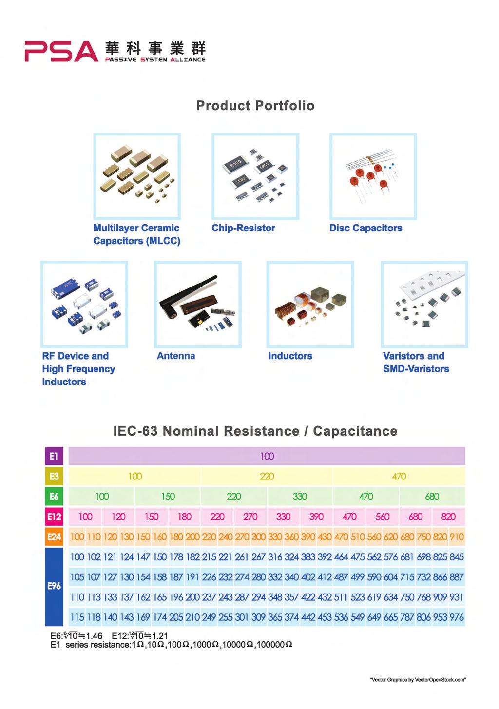
3 Table of Contents Subject INDEX Page s-5d Series... 3 s-7d Series... 4 s-10d Series... 5 s-14d Series... 6 s-20d Series... 7 s-25d Series... 8 s-5e 7E Series... 9 s-10e 14E Series s-18e 20E Series V-I Curve Packing Specification (5Ø - 25Ø Series) Taping Specifications - 5Ø and 7Ø Taping Specifications - 10Ø and 14Ø Taping Specifications - 18Ø and 20Ø Big Size - 32D Series Big Size - 34mm Single Series Big Size - 34mm Dual Series Big Size - 40D Series Big Size - 53D Series Packing of Big MOV and Soldering of MOV Multilayer Chip (MLV) *Thespecificationsaresubjecttochangeorourproductsinitmaybediscontinuedwithoutadvancenotice.Pleasecheckwith oursalesrepresentativesorproductengineersbeforeordering. *Thiscataloghasonlytypicalspecificationsbecausethereisnospacefordetailedspecifications.Therefore,pleaseapproveour productspecificationsortransacttheapprovalsheetforproductspecificationbeforeordering.
4 Metal Oxide (MOV) HO TO ORDER SR 241 K 10 D S 40 C X Type Code SR: alsin (DCvolt) (From180to 112) Twosignificant digits Followedbyno. ofzeros 180=18volt 101=100volt 102=1000volt Tolerance J:±5% K:±10% Disk Size Code 05:5mm 07:7mm 10:10mm 14:14mm 18:18mm 20:20mm 25:25mm Disk type D:Standard disktype E:High energydisk type Lead Type or Taping Code S:StraightLead L:InlineCrimped O:OutwardCrimped I:InwardCrimped TapingCode (Pleaseseebelow) Lead Cutting LeadCutting forbulk Packing: A0=10±1.0mm B0=19mmmin C0=29mmmin D0=39mmmin E0=49mmmin F0=10mmmin H0=30mmmin G0=20mmmin L0=50mmmin I0=40mmmin A5=15±1.0mm G5=25mmmin Coating -P=Phenolic coating -B=Phenolic coating -S=Siliconecoating -F=HFEpoxy coating -Y=ithoutcoating -T=Epoxycoating *I f customershavenospecialrequestonleadshape,weprovidestraightleadforvoltagetype 471Kandin-linecrimpedleadforvoltagetype 511K. Spacial Request Special leadcutting tolerance Speciallead spacing(please seebelow) Specialvaristor voltage range...etc VARISTOR SPECIAL REQUEST VARISTOR PART NUMBER EXAMPLES : F:0.5mmleadlengthtoleranceforshortleadcutting(excludestraightlead) Ex.1. SR241K07DT14:7mm,241K,inwardcrimpedleadandreel X:7.5mmleadspacingfor20Dand20E(leadwireis0.8mmdiameter) taped. Z:5mmleadspacingfor10D(E),14D(E) Ex.2. SR361K10DI45:10mm,361K,bulkpacking,inwardcrimped H:Specialrequest lead,leadcuttinglength4.5±1.0mm Ex.3. SR621K20EOP2:20mm,621K,highenergy,bulk,outward crimpedlead,leadspacing12mm±1.0mm. Ex.4. SR271K20DO65X:20mm,271K,bulk,outwardcrimpedlead, leadspacing7.5mm,leadcutting6.5±1.0mm Ex.5. SR241K10DS40F:10mm,241K,bulk,straightlead,lead cutting4.0±0.5mm. DIMENSIONS QUICK REFERENCE :Ifspecificitem sdimensions,pleasecontactsales Series 5D,5E 7D,7E 10D,10E 14D,14E 18E 20D,20E 25D Dmax d* ** Hmax H1max Tmax *±0.02**±1.0 (Unit:mm) Remark: Theleadlength(L)is20mm minimumunlessrequestedby customers;pleaserefertolead cuttingcodein HowtoOrder. 1

5 Metal Oxide (MOV) CHARACTERISTICS Highperformancetransientvoltagesuppression Shortresponsetimetosurgevoltage Lowstandbypowerdissipation Excellentclampingcharacteristics Highperformancewithstandingsurgecurrents Highreliability UL,CSA,VDEandCQCrecognized APPLICATIONS Surgeprotectionin: Consumerelectronics Industrialelectronics Communicationelectronics Measuringandcontrollingsystems Electronichomeappliances Protectionagainstsurgesinducedbylightingstrikingincoming powerlines. Suppressionofsurgescausedbyswitchinginductiveloadssuch astransformers,relaysandcoils. Protectionofrectificationdiodes,SCRs,powertransistors, semiconductordevices,etc DEFINITION OF VARISTOR TERMS Rated RMS, Rated DC : Themaximumdesignatedvaluesofpowersystemvoltage thatmaybeappliedcontinuouslybetweentheterminalsof adevice. : Testcharacteristicthatisusedtoclassifyvaristorsbytype. Atestcurrentof1mADCistypicallyusedtodetermine varistorvoltageclassificationtype.voltageclamping characteristicscanbedefinedatvarioustestlevels. Rated Peak Single Pulse Transient Current : surgecurrent,8/20µswaveformwhichavaristoris ratedtowithstandforasinglesurge. Rated Single Pulse Transient Energy : allowableenergyforasingleimpulse(seespecified waveforms). Clamping : Measuredpeakvoltageacrossthedeviceterminalswhen acurrentimpulseofspecifiedamplitudeandwaveformis conductedthroughthevaristor. : capacitancevaluesaremeasuredatatestfrequency of1khz.valuesareonlyforreferencepurpose only,notsubjecttooutgoinginspection. ENERGY DERATING VERSUS TEMPERATURE GENERAL CHARACTERISTICS Storage Temperature : 55 Cto+125 C Operating Surface Temperature :125 C Operating Ambient Temperature : 55 Cto+85 C(withoutderating) -Temperature Coefficient :< 0.05%/ C Insulation Resistance :1000Mega-ohmminimum Hi Pot (Leads To Case, 1 Min.) : 2500VDC Response Time :<15Nero-seconds Epoxy Rating : 94V-0 Current / Energy Derating (>85 C ) : 2.5%/ C DC Leakage Current : 200µAmaximum(atratedDCworkingvoltage) Solderability : MIL-STD-202F Power Dissipation Ratings(P, in-watts) : DiscSize 11Vac~40Vac 50Vac~680Vac 5mm mm mm mm mm mm mm mm mm(single) mm(dual) mm mm AlldefinitionsareaccordingtoIEEEspecificationsC PEAK CURRENT PER PULSE VERSUS PULSE DURATION 2
6 s-5d Series Part Number Allowable ithstanding Surge Current Max. Clamping Engergy Acrms DC DC 1 time Vc Ip 2ms Min Max Amps Amps Joules pf Safety Approval SR180K05D SR220K05D SR270K05D SR330K05D SR390K05D SR470K05D SR560K05D SR680K05D SR820K05D SR101K05D SR121K05D SR151K05D SR181K05D SR201K05D SR221K05D SR241K05D SR271K05D SR301K05D SR331K05D SR361K05D SR391K05D SR431K05D SR471K05D SR511K05D SR561K05D SR621K05D SR681K05D Remark: 1. :Suffixadding;pleaserefer How to Order fordetails 2.Allpartsapprovedasfollows: (1) : UL 1449recognized(File#E309297). (2) : CSA 22.2#1certified(CertificateFile#LR ). (3)CQCrecognizedforallpartnumbers(CQC ) 3
7 s-7d Series Part Number Allowable ithstanding Surge Current Max. Clamping Engergy Acrms DC DC 1 time Vc Ip 2ms Safety Approval Min Max Amps Amps Joules pf SR180K07D SR220K07D SR270K07D SR330K07D SR390K07D SR470K07D SR560K07D SR680K07D SR820K07D SR101K07D SR121K07D SR151K07D SR181K07D SR201K07D SR221K07D SR241K07D SR271K07D SR301K07D SR331K07D SR361K07D SR391K07D SR431K07D SR471K07D SR511K07D SR561K07D SR621K07D SR681K07D Remark: 1. :Suffixadding;pleaserefer How to Order fordetails 2.Allpartsapprovedasfollows: (1) : UL 1449recognized(File#E309297). (2) : CSA 22.2#1certified(CertificateFile#LR ). (3) : VDE/CECC42000/42200/42201,IEC / / (Certificate# ) (4)CQCrecognizedforallpartnumbers(CQC ) 4
8 s-10d Series Part Number Allowable ithstanding Surge Current Max. Clamping Engergy Acrms DC DC 1 time Vc Ip 2ms Min Max Amps Amps Joules pf Safety Approval SR180K10D SR220K10D SR270K10D SR330K10D SR390K10D SR470K10D SR560K10D SR680K10D SR820K10D SR101K10D SR121K10D SR151K10D SR181K10D SR201K10D SR221K10D SR241K10D SR271K10D SR301K10D SR331K10D SR361K10D SR391K10D SR431K10D SR471K10D SR511K10D SR561K10D SR621K10D SR681K10D SR751K10D SR781K10D SR821K10D SR911K10D SR102K10D SR112K10D Remark: 1. :Suffixadding;pleaserefer How to Order fordetails 2.Allpartsapprovedasfollows: (1) : UL 1449recognized(File#E309297). (2) : CSA 22.2#1certified(CertificateFile#LR ). (3) : VDE/CECC42000/42200/42201,IEC / / (Certificate# ) (4)CQCrecognizedforallpartnumbers(CQC ) 5
9 s-14d Series Part Number Allowable ithstanding Surge Current Max. Clamping Engergy Acrms DC DC 1 time Vc Ip 2ms Min Max Amps Amps Joules pf Safety Approval SR180K14D # SR220K14D # SR270K14D # SR330K14D # SR390K14D # SR470K14D # SR560K14D # SR680K14D # SR820K14D # SR101K14D # SR121K14D # SR151K14D # SR181K14D # SR201K14D # SR221K14D # SR241K14D # SR271K14D # SR301K14D # SR331K14D # SR361K14D # SR391K14D # SR431K14D # SR471K14D # SR511K14D # SR561K14D # SR621K14D # SR681K14D # SR751K14D # SR781K14D # SR821K14D # SR911K14D # SR102K14D # SR112K14D # Remark: 1. :Suffixadding;pleaserefer How to Order fordetails 2.Allpartsapprovedasfollows: (1) : UL 1449recognized(File#E309297). (2) : CSA 22.2#1certified(CertificateFile#LR ). (3) : VDE/CECC42000/42200/42201,IEC / / (Certificate# ) (4)#:VDE/IEC ,AnnexQ(Certificate# ) (5)CQCrecognizedforallpartnumbers(CQC ) 6
10 s-20d Series Part Number Allowable ithstanding Surge Current Max. Clamping Engergy Acrms DC DC 1 time Vc Ip 2ms Min Max Amps Amps Joules pf Safety Approval SR390K20D SR470K20D SR560K20D SR680K20D SR820K20D SR101K20D SR121K20D SR151K20D SR181K20D SR201K20D SR221K20D SR241K20D SR271K20D SR301K20D SR331K20D SR361K20D SR391K20D SR431K20D SR471K20D SR511K20D SR561K20D SR621K20D SR681K20D SR751K20D SR781K20D SR821K20D SR911K20D SR102K20D SR112K20D Remark: 1. :Suffixadding;pleaserefer How to Order fordetails 2.Allpartsapprovedasfollows: (1) : UL 1449recognized(File#E309297). (2) : CSA 22.2#1certified(CertificateFile#LR ). (3) : VDE/CECC42000/42200/42201,IEC / / (Certificate# ) (4)CQCrecognizedforallpartnumbers(CQC ) 7
11 s-25d Series Part Number Allowable ithstanding Surge Current Max. Clamping Engergy Acrms DC DC 1 time Vc Ip 2ms Min Max Amps Amps Joules pf Safety Approval SR181K25D SR201K25D SR221K25D SR241K25D SR271K25D SR301K25D SR331K25D SR361K25D SR391K25D SR431K25D SR471K25D SR511K25D SR561K25D SR621K25D SR681K25D SR751K25D SR781K25D SR821K25D SR911K25D SR102K25D SR112K25D Remark: 1. :Suffixadding;pleaserefer How to Order fordetails 2.Allpartsapprovedasfollows: (1) : UL 1449recognized(File#E309297). (2) : CSA 22.2#1certified(CertificateFile#LR ). (3) CQC recognizedforallpartnumbers(cqc ) 8
12 s-5e/7e Series Part Number Allowable ithstanding Surge Current Max. Clamping Engergy Acrms DC DC 1 time Vc Ip Safety Approval Min Max Amps Amps Joules pf SR820K05E SR181K05E SR201K05E SR221K05E SR241K05E SR271K05E SR301K05E SR331K05E SR361K05E SR391K05E SR431K05E SR471K05E SR511K05E SR561K05E SR621K05E SR681K05E Remark: 1. :Suffixadding;pleaserefer How to Order fordetails 2.Allpartsapprovedasfollows: (1) : UL 1449recognized(File#E309297). (2) : CSA 22.2#1certified(CertificateFile#LR ). (3) : VDE/CECC42000/42200/42201,IEC / / (Certificate# ) (4)#:VDE/IEC ,AnnexQ(Certificate# ) (5)CQCrecognizedforallpartnumbers(CQC ~CQC ) Part Number Allowable ithstanding Surge Current Max. Clamping Engergy Acrms DC DC 1 time Vc Ip Safety Approval Min Max Amps Amps Joules pf SR820K07E SR181K07E SR201K07E SR221K07E SR241K07E SR271K07E SR301K07E SR331K07E SR361K07E SR391K07E SR431K07E SR471K07E SR511K07E SR561K07E SR621K07E SR681K07E :Suffixadding;pleaserefer How to Order fordetails 2.Safetyapproval:pleasereferto"Remark"above. 9
13 s-10e/14e Series Part Number Allowable ithstanding Surge Current Max. Clamping Engergy Safety Approval Acrms DC DC 1 time Vc Ip Min Max Amps Amps Joules pf SR820K10E SR181K10E SR201K10E SR221K10E SR241K10E SR271K10E SR301K10E SR331K10E SR361K10E SR391K10E SR431K10E SR471K10E SR511K10E SR561K10E SR621K10E SR681K10E SR751K10E SR781K10E SR821K10E SR911K10E SR102K10E SR112K10E :Suffixadding;pleaserefer How to Order fordetails Allowable ithstanding Surge Current 2.Safetyapproval:pleasereferto"Remark"onpage9. Max. Clamping Engergy Safety Approval Part Number Acrms DC DC 1 time Vc Ip Min Max Amps Amps Joules pf SR820K14E # SR181K14E # SR201K14E # SR221K14E # SR241K14E # SR271K14E # SR301K14E # SR331K14E # SR361K14E # SR391K14E # SR431K14E # SR471K14E # SR511K14E # SR561K14E # SR621K14E # SR681K14E # SR751K14E # SR781K14E # SR821K14E # SR911K14E # SR102K14E # SR112K14E # 1. :Suffixadding;pleaserefer How to Order fordetails 2.Safetyapproval:pleasereferto"REMARK"ONPAGE9. 10
14 s-18e/20e Series Part Number Allowable ithstanding Surge Current Max. Clamping Engergy Acrms DC DC 1 time Vc Ip Min Max Amps Amps Joules pf Safety Approval SR820K18E # SR181K18E # SR201K18E # SR221K18E # SR241K18E # SR271K18E # SR301K18E # SR331K18E # SR361K18E # SR391K18E # SR431K18E # SR471K18E # SR511K18E # SR561K18E # SR621K18E # SR681K18E # SR751K18E # SR781K18E # SR821K18E # SR911K18E # SR102K18E # SR112K18E # 1. :Suffixadding;pleaserefer How to Order fordetails 2.Safetyapproval:pleasereferto"Remark"onpage9. Part Number Allowable ithstanding Surge Current Max. Clamping Engergy Acrms DC DC 1 time Vc Ip Min Max Amps Amps Joules pf Safety Approval SR820K20E # SR181K20E # SR201K20E # SR221K20E # SR241K20E # SR271K20E # SR301K20E # SR331K20E # SR361K20E # SR391K20E # SR431K20E # SR471K20E # SR511K20E # SR561K20E # SR621K20E # SR681K20E # SR751K20E # SR781K20E # SR821K20E # SR911K20E # SR102K20E # SR112K20E # 1. :Suffixadding;pleaserefer How to Order fordetails 2.Safetyapproval:pleasereferto"Remark"onpage9. 11
15 V-I CURVE 12
16 V-I CURVE 13
17 V-I CURVE 14
18 Packing Specifications (5Ø - 25Ø Series) A. A. Bulk packing: Q'ty Disk size mm Q'ty pcs/bag Disk size mm Q'ty pcs/bag pcs/carton Q'ty pcs/carton 5f All Ø AllA. Bulk packing: f All Q'ty 7Ø All Disk size mm 500 Q'ty pcs/bag5000 pcs/carton 180K-471K 5f 500 All f 180K-471K Ø Above511K 7f 300 All Above511K K-471K K-751K 180K-751K 10f Ø 14f Above511K Above821K K-751K Ø All All 14f 18f 200 Above821K K-621K 18f All Ø 20f Above681K Above681K 180K-621K f Above681K K-621K Ø 180K-621K K-621K f Above681K 25f Above681K 30 Above681K L Carton size of bulk packing Carton size of bulk packing H H L approx.395mm L approx.395mm L approx.285mm approx.285mm H approx.180mm H approx.180mm B. B. Tape and Reel: Disk size mm AMMO BOX REEL Disk size mm 5f PCS / BOX 431KBOX / CARTON 1500 PCS 10/ REEL 1500 REELS / BOX 2 BOX / CARTON 5 5f 471K f 431K 1500 PCS / BOX BOX 10 / CARTON 1500 PCS / REEL 2 REELS / BOX 5 BOX / CARTON 7f 431K Ø 5f 471K 431K f 471K Ø 7f 431K 471K 10f K Ø 7f 471K 431K 10f K Ø 471K 14f K f 431K f 471K Ø 431K f 471K 18f K Ø 471K f 431K 18f K Ø 431K 20f K f 471K Ø 471K 20f K f 431K Ø 431K Note:Ammoboxandreelquantitiesmayvary.Pleasecontactsalesfordetails Ø 18f 471K 471K Ø 20f 431K 431K Dimensions 500of 500 Ammo Box 8and Reel: Ø 20f 471K 471K 300 Ammo 300 Dimension Reel Dimension Note:Ammoboxandreelquantitiesmayvary.Pleasecontactsalesfordetails. A Dimensions of Ammo Box and Reel: B A approx.50mm Label B Reel Dimension D350f max Ammo Dimension Reel Dimension Aapprox.30f Bapprox.95f C Dimensions of Ammo Box and Reel: Taping Code: B. Tape and Reel: Disk size mm Disk size 5 f 7 f 10 f AMMO BOX A (max.) B (max.) C (max.) 50mm A 270mm 350mm 50mm 270mm 350mm B A AMMO BOX PCS / BOX BOX / CARTON approx.50mm D350f max Aapprox.30f Bapprox.95f Lead type series Lead spacing Packing type Lead type series Lead spacing Packing typestraight Outward crimped Outward Inward crimped Inward Inline crimped Straight Inline crimped 5D,5E 5 mm AmmoReel T11,T01 T17,T03 crimpedt1d,t14 crimped T1,T32 7D,7E 5D,5E 5 mm 5 mm AmmoReel AmmoReel T11,T01 T11,T01 T17,T03 T17,T03T1D,T14 T1D,T14 T1,T32 T1,T32 10D,10E 7D,7E 7.5mm 5 AmmoReel AmmoReel T36,T19 T11,T01 T1U,T1N T17,T03T08,T16 T1D,T14 T43,T04 T1,T32 14D,14E 10D,10E 7.5mm 7.5mm AmmoReel AmmoReel T36,T19 T36,T19 T1U,T1N T1U,T1NT08,T16 T08,T16 T43,T04 T43,T04 14D,14E 18E 7.5mm 7.5mm AmmoReel AmmoReel T44,T1HT36,T19 T45,T1X T1U,T1NT40,T4X T08,T16 T02,T25 T43,T04 20D,20E 18E 10mm 7.5mm AmmoReel AmmoReel T05,T30 T44,T1H T50,T2X T45,T1X T35,T2D T40,T4X T60,T3X T02,T25 20D,20E 10mm AmmoReel T05,T30 T50,T2X T35,T2D T60,T3X B A PCS / REEL REEL REEL REELS / BOX BOX / CARTON Label 70mm 270mm 370mm approx.50mm 14 f B70mm 270mm 370mm D350f max 18 f, f 70mm 270mm 370mm Aapprox.30f Bapprox.95f C Taping Code: Disk size size A (max.) A (max.) B (max.) C B (max.) C (max.) D D Lead type series Lead spacing Packing type 5 5 f Ø 50mm 50mm 270mm 350mm Straight Outward crimped Inward crimped Inline crimped 270mm 350mm 7 7Ø f 50mm 50mm 270mm 5D,5E 350mm 5 mm AmmoReel T11,T01 T17,T03 T1D,T14 T1,T32 270mm 350mm 7D,7E 5 mm AmmoReel T11,T01 T17,T03 T1D,T14 T1,T Ø f 70mm 70mm 270mm 370mm 10D,10E 270mm 7.5mm 370mm AmmoReel T36,T19 T1U,T1N T08,T16 T43,T Ø f 70mm 70mm 270mm 14D,14E 370mm 270mm 7.5mm 370mm AmmoReel T36,T19 T1U,T1N T08,T16 T43,T Ø,20Ø f, f 70mm 70mm 270mm 18E370mm 270mm 7.5mm 370mm AmmoReel T44,T1H T45,T1X T40,T4X T02,T25 20D,20E 10mm AmmoReel T05,T30 T50,T2X T35,T2D T60,T3X D 15
 T01(Reel) T17(AmmoBox) T03(Reel) T17(AmmoBox) T03(Reel) D P2 P A H1 2 H0 1 L 0 d P1 F LX D0 P0 T1D(AmmoBox) T1D(AmmoBox) T14(Reel) T14(Reel) D P2 P Δh T1(AmmoBox) T1(AmmoBox)")
19 Taping Specifications - 5Ø and 7Ø Δh T11(AmmoBox) T01(Reel) T17(AmmoBox) T03(Reel) T17(AmmoBox) T03(Reel) D P2 P A H1 2 H0 1 L 0 d P1 F LX D0 P0 T1D(AmmoBox) T1D(AmmoBox) T14(Reel) T14(Reel) D P2 P Δh T1(AmmoBox) T1(AmmoBox) T32(Reel) T32(Reel) D P2 P Δh A A H1 2 H1 2 H0 H0 1 L 0 1 L 0 d P1 F D0 LX d P1 F D0 LX P0 P0 Item Disk Size 5Ø (5D, 5E) Disk Size 7Ø (7D, 7E) Item TapingCode T11,T01 5Φ T17,T03,T14,T1D (5D, 5E) T32,T1 T11,T01 T17,T03,T14,T1D 7Φ (7D, 7E) T32,T1 T17,T03,T14, BodyDiameterTapingCode DT11,T017Max T32,T1 T1D 7Max T32,T17Max T11,T01 9Max T17,T03,T14,T1D 9Max 9Max LeadireDiameter BodyDiameter D d 7Max0.6± Max 0.6± Max 0.6± ±0. 9Max ±0. 9Max ±0. 9Max0 5 PitchofComponent LeadireDiameter d P ± ± ±1 12.7± ± ±1 0.6 FeedHolePitch PitchofComponent FeedHoleCentertoLead FeedHolePitch P P0 P012.7±12.7±0.3 P12.7± ± ±112.7± ± ± ±12.7± ± ± ± ±1 3.85± ± ± ±1 3.85± ± ± ±1 3.85± ±0.3 LeadtoLeadDistance(CentertoCenter) FeedHoleCentertoLead P1 F3.85±0.75.0± ±0.75.0± ± ± ± ± ± ± ± ±0.8 ComponentAlignment LeadtoLeadDistance(Centerto F Δh5.0±0.82.0Max 5.0±0.82.0Max 5.0±0.82.0Max 2.0Max 5.0± Max 5.0± Max 5.0±0.8 Center) BasepaperTapeidth 18* 18* 18* 18* 18* 18* ComponentAlignment Δ h 2.0Max 2.0Max 2.0Max 2.0Max 2.0Max 2.0Max AdhesiveTapeidth 0 10Min 10Min 10Min 10Min 10Min 10Min BasepaperTapeidth 18* 18* 18* 18* 18* 18* HolePosition 1 9±0.5 9±0.5 9±0.5 9±0.5 9±0.5 9±0.5 AdhesiveTapeidth 0 10Min 10Min 10Min 10Min 10Min 10Min AdhesiveTapeBorder 2 1.5Max 1.5Max 1.5Max 1.5Max 1.5Max 1.5Max HolePosition 1 9±0.5 9±0.5 9±0.5 9±0.5 9±0.5 9±0.5 ComponentHeight H1 30Max 30Max 30Max 32Max 32Max 30Max AdhesiveTapeBorder Lead-ireClinchHeight 2 1.5Max H0 1.5Max 16± Max 16± Max 1.5Max 16± Max 16±0.5 Lead-ireProtrusion ComponentHeight H1 30Max Lx 1.0Max 30Max1.0Max 30Max1.0Max 1.0Max 32Max 1.0Max 32Max 1.0Max 30Max FeedHoleDiameter Lead-ireClinchHeight H0 D0 4±0.2 16±0.5 4±0.2 16±0.54±0.2 4±0.2 4±0.2 16±0.5 16±0.5 4±0.2 TotalTapeThickness Lead-ireProtrusion LengthofClippedLead FeedHoleDiameter LX D0 t 1.0Max <0.7 L 4±0.2 11Max 1.0Max <0.7 4±0.2 11Max 1.0Max<0.7 4±0.211Max 1.0Max <0.7 11Max 4±0.2 < Max 11Max 4± Max <0.7 11Max 4±0.2 ComponentHeightfromSeatingPlane TotalTapeThickness t A <0.7 <0.7 13Max <0.7 13Max <0.7 15Max <0.7 15Max <0.7 HoleCentertoComponentCenter LengthofClippedLead L P211Max6.35±0.7 11Max6.35±0.7 11Max 6.35± ±0.7 11Max 6.35±0.7 11Max 6.35±0.7 11Max BasedonEIA-468-BSpecification ComponentHeightfromSeatingPlane A 13Max 13Max *Tolerancesare+1.0and Max 15Max Alldimensionsareinmillimeters. HoleCentertoComponentCenter P2 6.35± ± ± ± ± ±0.7 BasedonEIA-468-BSpecification *Tolerancesare+1.0and-0.5 Alldimensionsareinmillimeters. 16
20 Taping Specifications - 10Ø and 14Ø h h T36(AmmoBox) T19(Reel) D P2 P T1U(AmmoBox) T1N(Reel) D P2 P A 2 d H1 18 ± 2 2 d H1 16 ± 1 1 L 0 1 L 0 F F P0 D0 LX P0 D0 LX Δh Δh T08(AmmoBox) T16(Reel) D P2 P T43(AmmoBox) T04(Reel) D P2 P A A 2 0 L d H1 16 ± L d H1 16 ± 1 1 P0 F D0 LX P0 F D0 LX Item Disk Size 10Ø (10D, 10E) 14Ø (14D, 14E) TapingCode T19,T36 T1N,T1U,T08,T16 T43,T04 T11,T01 T1N,T1U,T08,T16 T43,T04 BodyDiameter D 14Max 14Max 14Max 17.5Max 17.5Max 17.5Max LeadireDiameter d 0.8± ± ± ± ± ±0.05 PitchofComponent P 25.4±1 25.4±1 25.4±1 25.4±1 25.4±1 25.4±1 HoleCentertoComponentCenter P2 12.7± ± ± ± ± ±0.3 FeedHolePitch P0 12.7± ± ± ± ± ±0.3 LeadtoLeadDistance(CentertoCenter) F 7.5± ± ± ± ± ±0.8 ComponentAlignment Δh 2.0Max 2.0Max 2.0Max 2.0Max 2.0Max 2.0Max BasepaperTapeidth 18* 18* 18* 18* 18* 18* AdhesiveTapeidth 0 10Min 10Min 10Min 10Min 10Min 10Min HolePosition 1 9±0.5 9±0.5 9±0.5 9±0.5 9±0.5 9±0.5 AdhesiveTapeBorder 2 1.5Max 1.5Max 1.5Max 1.5Max 1.5Max 1.5Max ComponentHeight H1 33Max 38.5Max 35.5Max 37Max 40Max 40Max Lead-ireProtrusion Lx 1.0Max 1.0Max 1.0Max 1.0Max 1.0Max 1.0Max FeedHoleDiameter D0 4±0.2 4±0.2 4±0.2 4±0.2 4±0.2 4±0.2 TotalTapeThickness t <0.7 <0.7 <0.7 <0.7 <0.7 <0.7 LengthofClippedLead L 11Max 11Max 11Max 11Max 11Max 11Max ComponentHeightfromSeatingPlane A 19.5Max 19.5Max 22.5Max 22.5Max BasedonEIA-468-BSpecification *Tolerancesare+1.0and-0.5 Alldimensionsareinmillimeters. 17
21 Taping Specifications - 18Ø and 20Ø 7.5mmLeadSpacing T44(AmmoBox) T1H(Reel) 10mmLeadSpacing T05(AmmoBox) T30(Reel) D P2 P h 7.5mmLeadSpacing T45(AmmoBox) T1X(Reel) 10mmLeadSpacing T50(AmmoBox) T2X(Reel) D P2 P h A 2 d H1 18 ± 2 2 d H1 16 ± 1 1 L 0 1 L 0 F F P0 D0 LX P0 D0 LX Δh 7.5mmLeadSpacing T40(AmmoBox) T4X(Reel) 10mmLeadSpacing T35(AmmoBox) T2D(Reel) D P2 P 7.5mmLeadSpacing T02(AmmoBox) T25(Reel) 10mmLeadSpacing T60(AmmoBox) T3X(Reel) D P2 P Δh A A 2 0 L d H1 16 ± L d H1 16 ± 1 1 P0 F D0 LX P0 F D0 LX Disk Size Item 20Φ (20D, 20E), 18Φ (18E) Disk Size 20Φ (20D, 20E) Lead Spacing 7.5 mm Lead Spacing 10.0 mm Item 20Ø T45,T1X,T40, (20D, 20E), 18Ø (18E) 20Ø T50,T2X,T35, (20D, 20E) TapingCode T44,T1H T02,T25 T05,T30 T60,T3X T4X T2D BodyDiameter D 24Max** 24Max** 24Max** Lead Spacing 7.5 mm 24Max 24Max 24Max Lead Spacing 10.0 mm LeadireDiameter d 0.8± ± ± ± ± ±0.1 TapingCode T44,T1H T45,T1X,T40,T4X T02,T25 T05,T30 T50,T2X,T35,T2D T60,T3X PitchofComponent P 25.4±1 25.4±1 25.4±1 25.4±1 25.4±1 25.4±1 BodyDiameter D 24Max** 24Max** 24Max** 24Max 24Max 24Max HoleCentertoComponentCenter LeadireDiameter P2 12.7±0.3 d 0.8± ± ± ± ± ± ± ± ± ± ± FeedHolePitch P0 12.7± ± ± ± ± ±0.3 PitchofComponent P 25.4±1 25.4±1 25.4±1 25.4±1 25.4±1 25.4±1 LeadtoLeadDistance(Centerto F 7.5± ± ± ± ± ±1.0 HoleCentertoComponentCenter Center) P2 12.7± ± ± ± ± ±0.3 FeedHolePitch ComponentAlignment Δ h P0 2.0Max 12.7± Max12.7± Max 12.7± Max 12.7± ± Max 2.0Max 12.7±0.3 LeadtoLeadDistance(CentertoCenter) BasepaperTapeidth F 18* 7.5±0.8 18* 7.5±0.8 18* 7.5± ±1.0 18* 10.0±1.0 18* 18* 10.0±1.0 ComponentAlignment AdhesiveTapeidth 0 Δh10Min2.0Max 10Min 2.0Max 10Min2.0Max 10Min 2.0Max 10Min 2.0Max 10Min 2.0Max BasepaperTapeidth HolePosition 1 9±0.5 18* 9±0.5 18* 9±0.5 18* 9±0.5 18* 9±0.5 18* 9±0.518* AdhesiveTapeidth AdhesiveTapeBorder Max10Min 1.5Max 10Min 1.5Max10Min 1.5Max 10Min 1.5Max 10Min 1.5Max 10Min HolePosition ComponentHeight H1 1 48Max** 9±0.5 48Max** 9±0.5 48Max** 9±0.5 48Max 9±0.5 48Max 9±0.5 48Max 9±0.5 AdhesiveTapeBorder Lead-ireProtrusion LX 21.0Max1.5Max 1.0Max1.5Max 1.0Max1.5Max 1.0Max 1.5Max 1.0Max 1.5Max 1.0Max 1.5Max ComponentHeight H2 48Max** 48Max** 48Max** 48Max 48Max 48Max FeedHoleDiameter D0 4±0.2 4±0.2 4±0.2 4±0.2 4±0.2 4±0.2 Lead-ireProtrusion Lx 1.0Max 1.0Max 1.0Max 1.0Max 1.0Max 1.0Max TotalTapeThickness t <0.7 <0.7 <0.7 <0.7 <0.7 <0.7 FeedHoleDiameter D0 4±0.2 4±0.2 4±0.2 4±0.2 4±0.2 4±0.2 LengthofClippedLead L 11Max 11Max 11Max 11Max 11Max 11Max TotalTapeThickness t <0.7 <0.7 <0.7 <0.7 <0.7 <0.7 ComponentHeightfromSeatingPlane LengthofClippedLead A L 11Max 29Max** 11Max 28Max** 11Max 11Max 29Max 11Max 28Max 11Max BasedonEIA-468-BSpecification ComponentHeightfromSeatingPlane A 29Max** *Tolerancesare+1.0and Max** 29Max 28Max Alldimensionsareinmillimeters. BasedonEIA-468-BSpecification *Tolerancesare+1.0and-0.5 Alldimensionsareinmillimeters. **For18Ø,D=22max,H1=46maxandA=26max. 18
22 Big Size - 32D Series StraightLeadsPartNumberNoSuffix 90 BendLeadsPartNumberSuffix Q 40.0MAX. T 40.0MAX. T 56.0MAX. 51.0MAX. 3.0TYP. 7.04±0.2 φ3.40± ± ± TYP. 7.04± ± TYP. 0.51±0.05 S S d φ3.40±0.1 Ratings Electrical Characteristics Part Number Continuous Rated AC RMS DC Rated Single Pulse Transient Energy 10/1000μs Jules Peak 8/20μs 1mA DC Min Max Test Current 25 Tmax. s d Amps PF mm mm mm SR201K32D ± ±1.0 SR221K32D ± ±1.0 SR241K32D ± ±1.0 SR271K32D ± ±1.0 SR331K32D ± ±1.0 SR361K32D ± ±1.0 SR391K32D ± ±1.0 SR431K32D ± ±1.0 SR471K32D ± ±1.0 SR511K32D ± ±1.0 SR621K32D ± ±1.0 SR681K32D ± ±1.0 SR751K32D ± ±1.0 SR781K32D ± ±1.0 SR821K32D ± ±1.0 SR911K32D ± ±1.0 SR951K32D ± ±1.0 SR102K32D ± ±1.0 SR112K32D ± ± PartNumberSuffixCode(ie:SR201K32DML) No suffix - Straight Lead Q - 90º Bend Lead L - Straight Lead LeftSideLeadOrientation R - Uncoated Disk withoutleads F Un-Coated Disk withleads M One Side Coated Disk withonerightorientationleadonly ML One Side coated Disk withoneleftorientationleadonly N Uncoated Disk withonerightorientationleadonly NL Uncoated Disk withoneleftorientationleadonly UL1449recognized(File#E309297) CSA22.2#1certified(File#206608)
23 Big Size - 34mm Single Series Straight Leads Part Number No Suffix 90 Bend Leads Part Number Suffix Q 42.0 MAX. T 42.0 MAX. T 42.0 MAX TYP. 3.0 TYP.. φ3.40± ± ± TYP. S 0.51± ±0.2 φ3.40± ± TYP. 0.5±0.05 d 8.0±0.5 Ratings Electrical Characteristics Rated RatingsSingle Electrical Characteristics Continuous Pulse Transient Continuous Rated Single Clamping Clamping CapacitancTmax. s d Part Rated S d Part Rated Pulse Transient Tmax. e 1mA DC Number Energy 1mA Test Current 25 Energy Peak 8/20μs AC RMS DC 25 10/1000s 8/20μs Min Max AC Amps PF mm mm mm DC 10/1000μs Jules 8/20μs K Amps Min Max RMS Amps PF mm mm mm SR201K34R Jules 310 KAmps ± ±1.0 SR221K34R ± ±1.0 SR201K34R ± ±1.0 SR241K34R ± ±1.0 SR221K34R SR271K34R ± ± ± ±1.0 SR241K34R SR301K34R ± ± ± ±1.0 SR331K34R SR271K34R ± ± ± ±1.0 SR361K34R ± ±1.0 SR301K34R SR391K34R ± ± ± ±1.0 SR331K34R SR431K34R ± ± ± ±1.0 SR361K34R SR471K34R ± ± ± ±1.0 SR511K34R ± ±1.0 SR391K34R ± ±1.0 SR561K34R ± ±1.0 SR431K34R SR621K34R ± ± ± ±1.0 SR471K34R SR681K34R ± ± ± ±1.0 SR511K34R SR751K34R ± ± ± ±1.0 SR781K34R ± ±1.0 SR561K34R ± ±1.0 SR821K34R ± ±1.0 SR621K34R SR911K34R ± ± ± ±1.0 SR681K34R SR951K34R ± ± ± ±1.0 SR751K34R SR102K34R ± ± ± ±1.0 SR112K34R ± ±1.0 SR781K34R ± ±1.0 SR821K34R ± ±1.0 -PartNumberSuffixCode(ie:SR201K32RML) SR911K34R No suffix - Straight 550Lead L - Straight 1500 Lead 300 Left Side Lead 2100 Orientation ± ±1.0 SR951K34R Q - 90º Bend Lead R - Uncoated 1570 Disk 300 without Leads ± ±1.0 F Un-Coated Disk with Leads M One Side Coated Disk with one Right Orientation Lead only SR102K34R ± ±1.0 ML One Side coated Disk with one Left Orientation Lead only N Uncoated Disk with one Right Orientation Lead only SR112K34R NL Uncoated Disk 680 with 895 one Left Orientation 1350 Lead only ± ±1.0 -PartNumberSuffixCode(ie:SR201K32RML) UL1449recognized(File#E309297) CSA22.2#1certified(File#206608) No suffix - Straight Lead L - Straight Lead LeftSideLeadOrientation Q - 90º Bend Lead R - Uncoated Disk withoutleads F Un-Coated Disk withleads M One Side Coated Disk withonerightorientationleadonly ML One Side coated Disk withoneleftorientationleadonly N Uncoated Disk withonerightorientationleadonly NL Uncoated Disk withoneleftorientationleadonly UL1449recognized(File#E309297) CSA22.2#1certified(File#206608) 20
24 Big Size 34mm Dual Series Part Number Continuous Rated AC RMS DC Ratings Energy 10/1000μs Jules Rated Single Pulse Transient Peak 8/20μs KAmps Lead 1-2or2-3 8/20μs KAmps Lead 1mA DC Min Max Electrical Characteristics Test Current 25 Tmax. Amps PF mm mm SR221K34RD ±1.0 SR221K34RD ±1.0 SR241K34RD ±1.0 SR271K34RD ±1.0 SR301K34RD ±1.0 SR331K34RD ±1.0 SR361K34RD ±1.0 SR391K34RD ±1.0 SR431K34RD ±1.0 SR471K34RD ±1.0 SR511K34RD ±1.0 SR561K34RD ±1.0 SR621K34RD ±1.0 SR681K34RD ±1.0 SR751K34RD ±1.0 SR781K34RD ±1.0 SR821K34RD ±1.0 SR911K34RD ±1.0 SR951K34RD ±1.0 SR102K34RD ±1.0 SR112K34RD ±1.0 -PartNumberSuffixCode(ie:SR201K40DQ) No suffix - Straight Lead Q - 90º Bend Lead UL1449recognized(File#E309297) CSA22.2#1certified(File#206608) s 21
25 Big Size - 40D Series Ratings Electrical Characteristics Part Number Continuous Rated Rated Single Pulse Transient Energy 1mA DC Test Current 25 Tmax. s d AC RMS DC 10/1000μs Jules 8/20μs KAmps Min Max Amps PF mm mm mm SR201K40D ± ±1.0 SR221K40D ± ±1.0 SR241K40D ± ±1.0 SR271K40D ± ±1.0 SR331K40D ± ±1.0 SR361K40D ± ±1.0 SR391K40D ± ±1.0 SR431K40D ± ±1.0 SR471K40D ± ±1.0 SR511K40D ± ±1.0 SR621K40D ± ±1.0 SR681K40D ± ±1.0 SR751K40D ± ±1.0 SR781K40D ± ±1.0 SR821K40D ± ±1.0 SR911K40D ± ±1.0 SR951K40D ± ±1.0 SR102K40D ± ±1.0 SR112K40D ± ±1.0 -PartNumberSuffixCode(ie:SR201K53DQ) No suffix - Straight Lead Q - 90º Bend Lead L - Straight Lead LeftSideLeadOrientation R - Uncoated Disk withoutleads F Un-Coated Disk withleads M One Side Coated Disk withonerightorientationleadonly ML One Side coated Disk withoneleftorientationleadonly N Uncoated Disk withonerightorientationleadonly NL Uncoated Disk withoneleftorientationleadonly UL1449recognized(File#E309297) CSA22.2#1certified(File#206608) 22
26 Big Size - 53D Series Part Number Continuous Rated AC RMS Ratings DC Rated Single Pulse Transient Energy 10/1000μs Jules Peak 8/20μs 1mA DC Min Max Electrical Characteristics Test Current 25 Tmax. s d Amps PF mm mm mm SR201K53D ± ±1.0 SR221K53D ± ±1.0 SR241K53D ± ±1.0 SR271K53D ± ±1.0 SR331K53D ± ±1.0 SR361K53D ± ±1.0 SR391K53D ± ±1.0 SR431K53D ± ±1.0 SR471K53D ± ±1.0 SR511K53D ± ±1.0 SR561K53D ± ±1.0 SR621K53D ± ±1.0 SR681K53D ± ±1.0 SR751K53D ± ±1.0 SR781K53D ± ±1.0 SR821K53D ± ±1.0 SR911K53D ± ±1.0 SR951K53D ± ±1.0 SR102K53D ± ±1.0 SR112K53D ± ±1.0 SR122K53D ± ±1.0 -PartNumberSuffixCode(ie:SR201K53DQ) No suffix - Straight Lead L - Straight Lead LeftSideLeadOrientation Q - 90º Bend Lead R - Uncoated Disk withoutleads F Un-Coated Disk withleads M One Side Coated Disk withonerightorientationleadonly ML One Side coated Disk withoneleftorientationleadonly N Uncoated Disk withonerightorientationleadonly NL Uncoated Disk withoneleftorientationleadonly UL1449recognized(File#E309297) CSA22.2#1certified(File#206608) 23
27 V-I CURVE 24
28 Packing Packing of of Big Big MOV MOV and and Soldering Soldering of of MOV MOV Packing Specification of Big MOV (32~53mm) Disk size mm 32D Q'ty PCS/BOX Q'ty PCS/ CARTON 201K~391K K~621K K~122K K~391K Carton size of bulk packing H 34R 431K~621K K~122K D 201K~391K K~621K L L approx.395mm approx.285mm H approx.180mm 681K~122K K~391K D 431K~621K K~122K Pleaseconsultsalesfordetailspecification ave Soldering Profile 25
29 Multilayer Multilayer Chip Chip (MLV) (MLV) INTRODUCTION-PLATED & LEAD-FREE TERMINATION HighSpeedESDSuppressorisanadvancedseriesofalsin smultilayerchip(mlv). Nowadays,moreandmorecommunicationdevicesbecomecompactandapplydenserandhigherfrequency circuitsinside.protectionagainsttheelectronicstaticdischarge(esd)generatedfromhumanbodytransient voltagesurgeismoreimportantwhendownsizeofhigh-speedtransistormakesitsvulnerabilitytoesdand surge.alsin shighspeedesdsuppressorprovidesprotectionfromesdandeftinhigh-speed datalineandradiofrequency(rf)circuits.also,ifcapacitanceofmlvisaconcerntocircuitdesigners, alsinmlvhserieswouldsupplyasolution,mlvwithspecifiedcapacitanceandrange.itiscompatiblewith modernreflowandwavesolderingprocedures.ewouldgiveyouasolutiontotransientovervoltageandesd protectiontoyourproducts. FEATURES MultilayerFabricationTechnology Smallsize(0402&0603) -55 to125 OperatingTemperatureRange OperatingRangeVM(DC)=5.5V~38V AbletowithstandESDtestofIEC Bi-directionalClampingcharacteristic Standard/Low/customizedTypesAvailable Size L 1.00± ± ± ± ± ± ± ±0.20 T 0.50± ± ± ±0.10*, 1.10±0.20** a 0.25± ± ± ±0.25 Unit:mmNote:*meansVZ Vdc~22Vdcitems,**meansVZ Vdc~38Vdcitems TC Part Number Continuous orking VM(DC) Ratings Max. Clamping at Specified Current (8/20µs) VC Nominal at 1mA(DC) Current VN(DC) Min. Specifications VN(DC) Max. 1MHz C (V) (V) (V) (V) (pf) % VH0402M050CGT5R0 5 72at1A ~9 +80/-20% VH0402M050CGT at1A ~13 ±30% VH0402M050CGT at1A ~28.6 ±30% VH0402M050CGT at1A ~42.9 ±30% VH0402M050CGT at1A ~72.8 ±30% VH0402M050CGT at1A ~130 ±30% VH0402M120CGT5R at1A ~9 +80/-20% VH0402M120CGT at1A ±30% VH0402M120CGT at1A ±30% VH0402M120CGT at1A ±30% VH0402M120CGT at1A ±30% VH0402M120CGT at1A ±30% VH0402M240CGT0R at1A ~ /-20% VH0402M240CGT2R at1A ~ /-20% VH0603M050CGT5R0 5 55at1A ~9 +80/-20% VH0603M050CGT at1A ±30% VH0603M050CGT at1A ±30% VH0603M050CGT at1A ±30% VH0603M050CGT at1A ±30% VH0603M050CGT at1A ±30% VH0603M120CGT5R at1A ~9 +80/-20% VH0603M120CGT at1A ±30% VH0603M120CGT at1A ±30% VH0603M120CGT at1A ±30% VH0603M120CGT at1A ±30% VH0603M240CGT0R at1A ~ /-20% VH0603M240CGT2R at1A ~ /-20% 26 26
30 Multilayer Chip (MLV) Part Number Continuous orking ESD Trigger ESD Leakage Current VDC after 30ns Minimum ESD pulse 1MHz VM(DC) VT Clamp (V) µa Times Cp (pf) VH0402M240CGT0R <1μA >1000 <0.2 VH0402M240CGT0R <1μA >1000 <0.05 VH0603M240CGT0R <0.001 >1000 <0.2 VH0603M240CGT0R <0.001 >1000 <0.05 QUICK REFERENCE SPECIFICATIONS- VZ Series TC Part Number Continuous orking Ratings Non- Repetitive Surge Energy (8/20µs) Non- Repetitive Surge Energy (10/1000µs) Max. Clamping at Specified Current (8/20µs) Specifications Nominal at 1Ma(DC) Current VM VM VN ITM TM VC (DC) (AC) (DC) Min. VN (DC) 1MHz C (V) (V) (A) (J) (V) (V) (V) (Pf) VZ0402M050AGT at1A VZ0402M090AGT at1A VZ0402M140AGT at1A VZ0402M180AGT at1A VZ0603M050AGT at1A VZ0603M090AGT at1A VZ0603M140AGT at1A VZ0603M180AGT at1A VZ0603M220AGT at1A VZ0603M300AGT at1A VZ0805M050AGT at1A VZ0805M090AGT at1A VZ0805M140AGT at1A VZ0805M180AGT at1A VZ0805M220AGT at1A VZ0805M260AGT at1A VZ0805M300AGT at1A VZ0805M380AGT at1A VZ1206M050AGT at1A VZ1206M140AGT at1A VZ1206M180AGT at1A VZ1206M220AGT at1A VZ1206M260AGT at1A VZ1206M300AGT at1A VZ1206M380AGT at1A VZ1206M450AGT at1A VZ1206M560AGT at1A VZ1206M650AGT at1A VZ1206M850AGT at1A
31

32
Metal Oxide Varistors (MOV) Data Sheet
 Data Sheet") Φ SERIES Metal Oxide Varistors (MOV) Data Sheet Features Wide operating voltage (V ma ) range from 8V to 0V Fast responding to transient over-voltage Large absorbing transient energy capability Low clamping
Φ SERIES Metal Oxide Varistors (MOV) Data Sheet Features Wide operating voltage (V ma ) range from 8V to 0V Fast responding to transient over-voltage Large absorbing transient energy capability Low clamping
XKT. Metal Oxide Varistor FEATURES
 FEATURES Operating Temperature Range: -40 ~+105 Body Diameters Range From 5D to 20D Wide Operating from 18V to 1800V Full compliance with RoSH and REH DIMENSION L:16mm min SIZE D MAX H MAX d+-0.05 E c
VAR Series Zinc Oxide Varistor
 FEATURES Round Zinc Oxide, leaded Coating: epoxy resin, flame-retardant material Operating Temperature Range: -40 ~+105 Wide operating voltage Approvals: CQ C, UL, VDE RoHS 201165EU; REACH Compliant High
TSV. Suntan ZINC OXIDE VARISTOR. Operating Temperature Range: -40 ~+85 DIMENSION. T Thickness(max.) L:16mm min
 L:16mm min") Operating Temperature Range: -40 ~+85 DIMENSION L:16mm min SIZE D MAX H MAX d+-0.05 E c max D05 8 11 0.5 5±0.8 2.5 D07 10 12.5 0.5 5±0.8 2.5 D10 13.5 16 0.7 7.5±0.8 2.5 D14 17.5 20 0.7 7.5±0.8 2.5 D20
Operating Temperature Range: -40 ~+85 DIMENSION L:16mm min SIZE D MAX H MAX d+-0.05 E c max D05 8 11 0.5 5±0.8 2.5 D07 10 12.5 0.5 5±0.8 2.5 D10 13.5 16 0.7 7.5±0.8 2.5 D14 17.5 20 0.7 7.5±0.8 2.5 D20
YJM-L Series Chip Varistor
 Features 1. RoHS & Halogen Free (HF) compliant 2. EIA size: 0402 ~ 2220 3. Operating voltage: 5.5Vdc ~ 85Vdc 4. High surge suppress capability 5. Bidirectional and symmetrical V/I characteristics 6. Multilayer
1000 VDC 1250 VDC 125 VAC 250 VAC J K 125 VAC, 250 VAC
 Metallized Polyester Film Capacitor Type: ECQE(F) Non-inductive construction using metallized Polyester film with flame retardant epoxy resin coating Features Self-healing property Excellent electrical
Metal Oxide Varistor:TVR-D Series
 Features. RoHS compliant 2. Halogen-free series are available 3. Body size: Ф7mm ~ Ф 20mm 4. Wide operating voltage range: 5Vac ~ 680Vac 5. High surge current rating up to 3KA 6. High energy rating up
Metal Oxide Varistor:TVR Series
 Features. RoHS compliant 2. Halogen-free series are available 3. Body size: Ф5 ~ Ф20mm 4. Wide operating voltage range: Vac ~ 00 Vac 5. Operating temperature range: -40 C ~ +85 C Storage temperature range:
NTC Thermistor:TTC3 Series
 Features. RoHS compliant 2. Halogen-Free(HF) series are available 3. Body size: Ф3mm 4. Radial lead resin coated 5. Operating temperature range: -40 ~+25 6. Wide resistance range 7. Cost effective 8. Agency
ZNR Transient/Surge Absorbers (Type D)
") ZNR Transient/Surge Absorbers Type: Series: V Features arge withstanding surge current capability in compact sizes arge Energy andling Capability absorbing transient overvoltages in compact sizes ide range
ZNR Transient/Surge Absorbers Type: Series: V Features arge withstanding surge current capability in compact sizes arge Energy andling Capability absorbing transient overvoltages in compact sizes ide range
MULTILAYER CHIP VARISTOR JMV S & E Series: (SMD Surge Protection)
") INTRODUCTION Metal Oxide based chip varistors (JMVs) are used for transient suppression. JMVs have non-linear - behavior, which is similar to that of Zener Diode. Each grain in JMV exhibits small p-n junction
INTRODUCTION Metal Oxide based chip varistors (JMVs) are used for transient suppression. JMVs have non-linear - behavior, which is similar to that of Zener Diode. Each grain in JMV exhibits small p-n junction
NTC Thermistor:SCK Series
 Features. RoHS & Halogen Free (HF) compliant 2. Body size: Ф5mm ~ Ф30mm 3. Radial lead resin coated 4. High power rating 5. Wide resistance range 6. Cost effective 7. Operating temperature range: Ф5mm:
SIOV Metal Oxide Varistors Leaded Varistors (StandarD Series)
") Leaded Varistors () Disk varistors StandarD series, dimensions Construction Round varistor element, leaded Coating: epoxy resin, flame-retardant to UL 94 V-0 Terminals: tinned copper wire Features Wide
Leaded Varistors () Disk varistors StandarD series, dimensions Construction Round varistor element, leaded Coating: epoxy resin, flame-retardant to UL 94 V-0 Terminals: tinned copper wire Features Wide
NTC Thermistor:SCK Series
 Features. RoHS & Halogen Free (HF) compliant 2. Body size: Ф5mm ~ Ф30mm 3. Radial lead resin coated 4. High power rating 5. Wide resistance range 6. Cost effective 7. Operating temperature range: Ф5mm:
Polymer PTC Resettable Fuse:KMC Series
 Features 1. RoHS compliant 2. EIA size:1206~1812 3. Hold current ratings from 0.05 to 3A 4. Voltage ratings from 6V computer and electronic applications to 60V 5. Small footprint 6. Fast time to trip 7.
Polymer PTC Resettable Fuse: KRG Series
 Features 1. RoHS & Halogen-Free (HF) compliant 2. Radial leaded devices 3. Broadest range of resettable devices available in the industry 4. Hold current ratings from 0.1 to 3.75A 5. Maximum voltage is
NTC Thermistor:SCK Series
 Features. RoHS & Halogen Free (HF) compliant 2. Body size: Ф5mm ~ Ф30mm 3. Radial lead resin coated 4. High power rating 5. Wide resistance range 6. Cost effective 7. Operating temperature range: Ф5mm:
SMD Transient Voltage Suppressors
 SMD Transient Suppressors Feature Full range from 0 to 22 series. form 4 to 60V RMS ; 5.5 to 85Vdc High surge current ability Bidirectional clamping, high energy Fast response time
THICK FILM LEAD FREE CHIP RESISTORS
 Features Suitable for lead free soldering. Compatible with flow and reflow soldering Applications Consumer Electronics Automotive industry Computer Measurement instrument Electronic watch and camera Configuration
NTC Thermistor:SCK Series
 NTC Thermistor:SCK Series Features. RoHS & Halogen Free (HF) compliant 2. Body size: Ф5mm ~ Ф30mm 3. Radial lead resin coated 4. High power rating 5. Wide resistance range 6. Cost effective 7. Operating
Metal Oxide Varistor TVR Type
 Features. RoHS compliant 2. Body size Ф5~ Ф 20mm 3. Wide operating voltage range Vac ~ 00Vac 4. Large withstanding surge current capability 0 ~ 6500 (@8/20) 5. Radial lead resin coated 6. Excellent clamping
Thin Film Chip Resistors
 FEATURES PRECISE TOLERANCE AND TEMPERATURE COEFFICIENT EIA STANDARD CASE SIZES (0201 ~ 2512) LOW NOISE, THIN FILM (NiCr) CONSTRUCTION REFLOW SOLDERABLE (Pb FREE TERMINATION FINISH) Type Size EIA PowerRating
Metal Oxide Leaded Film Resistor
 SURFACE TEMP. RISE ( ) Power Ratio(%) MOF0623, 0932, 1145, 1550, 1765, 2485 MOF Series Features -Excellent Long-Time stability -High surge / overload capability -Wide resistance range : 0.1Ω~10MΩ -Controlled
Metal Oxide Leaded Film Resistor
 Features -Excellent Long-Time stability -High surge / overload capability -Wide resistance range : 0.1Ω~22MΩ -Controlled temperature coefficient -Resistance standard tolerance: ±5% (consult factory for
Transient Voltage Suppression Diodes: 1.5KE Series Axial Leaded Type 1500 W
 Features 1. Reliable low cost construction utilizing molded plastic technique 2. Both bi-directional and uni-directional devices are available 3. Fast response time 4. Excellent clamping capacity 5. 1500
NTC Thermistor:SCK Series
 Features. RoHS & HF compliant 2. Body size: Ф5mm ~ Ф 30mm 3. Radial lead resin coated 4. High power rating 5. Wide resistance range 6. Cost effective 7. Operating temperature range: Φ5mm:-40~+50 Φ8~Φ0mm:-40~+70
C121. External Dimensions (L W) (mm) 0603 [0201] [0402] [0603] [0805]
![C121. External Dimensions (L W) (mm) 0603 [0201] [0402] [0603] [0805]](/thumbs/90/101883046.jpg "C121. External Dimensions (L W) (mm) 0603 [0201] [0402] [0603] [0805]") Multilayer Chip SDV Series Operating Temp. : -55 ~+125 FEATURES SMD type suitable for high density mounting Excellent clamping ratio and quick response time (
Multilayer Chip SDV Series Operating Temp. : -55 ~+125 FEATURES SMD type suitable for high density mounting Excellent clamping ratio and quick response time (
Current Sensing Chip Resistor SMDL Series Size: 0201/0402/0603/0805/1206/1010/2010/2512/1225/3720/7520. official distributor of
 Product: Current Sensing Chip Resistor SMDL Series Size: 0201/0402/0603/0805/1206/1010/2010/2512/1225/3720/7520 official distributor of Current Sensing Chip Resistor (SMDL Series) 1. Features -3 Watts
CSR series. Thick Film Chip Resistor Current Sensing Type FEATURE PART NUMBERING SYSTEM ELECTRICAL CHARACTERISTICS
 FEATURE Operating Temperature: -55 ~ +155 C 3 Watts power rating in 1 Watt size, 1225 package High purity alumina substrate for high power dissipation Long side terminations with higher power rating PART
Metal Oxide Varistor (MOV) Data Sheet
 Data Sheet") Metal Oxide (MOV) Data Sheet Feature Wide operating voltage range from 82V to 1100V Operating Temperature: -40 ~ +125 Storage Temperature: 15 ~35 Applications The over-voltage protection for transistors,
Metal Oxide (MOV) Data Sheet Feature Wide operating voltage range from 82V to 1100V Operating Temperature: -40 ~ +125 Storage Temperature: 15 ~35 Applications The over-voltage protection for transistors,
Ceramic PTC Thermistor Overload Protection
 FEATURES compliant CPTD type are bare disc type CPTL type are leaded Low, medium and high voltage ratings Low resistance; Small size No need to reset supply after overload No noise generated Stable over
NTC Thermistor:SCK Series
 Features. RoHS & Halogen Free (HF) compliant 2. Body size: Ф5mm ~ Ф30mm 3. Radial lead resin coated 4. High power rating 5. Wide resistance range 6. Cost effective 7. Operating temperature range: Ф5mm:
CSK series. Current Sensing Chip Resistor. Features. Applications. Construction FAITHFUL LINK
 CSK series Current Sensing Chip Resistor Features» 3 Watts power rating in 1 Watt size, 1225 Package» Low TCR of ±100 PPM/ C» Resistance values from 1m to 1 ohm» High purity alumina substrate for high
Transient Voltage Suppressor
 Transient Suppressor Features Glass passivated junction Low incremental surge resistance, excellent clamping capability Underwriters Laboratory Recognition under UL standard for safety 497B: Isolated Loop
Multilayer Ceramic Chip Capacitors
 FEATURES X7R, X6S, X5R AND Y5V DIELECTRICS HIGH CAPACITANCE DENSITY ULTRA LOW ESR & ESL EXCELLENT MECHANICAL STRENGTH NICKEL BARRIER TERMINATIONS RoHS COMPLIANT SAC SOLDER COMPATIBLE* PART NUMBER SYSTEM
Metal Film Leaded Precision Resistor
 Features Excellent overall stability Very tight tolerance down to ±0.05% Extremely low TCR down to ±5 PPM/ C High power rating up to 3 Watts Excellent ohmic contact Construction Applications Telecommunication
Symbol. Parameter Value Unit. IPP See Next Table A IFSM
 5W Transient Suppressor.5KE-HF Series Stand-off : 6.8 ~ 6V Power Dissipation: 5 Watts RoHS Device Halogen Free Features -Glass passivated chip. -Low leakage. -5W peak pulse power capability with a /μs
Metal Film Flame-Proof Resistors
 Features -Low Noise -Low TCR from ±15~100PPM/ -High Precision from ±0.1%~1% -Complete Flameproof Construction UL-1412. -Coating meets UL94V-0 Applications -Telecommunication -Medical Equipment -Consumer
Carbon Film Leaded Resistor
 Features -The most economic industrial investment -Standard tolerance: +/-5% (available +/-2%) -Excellent long term stability -Termination: Standard solder-plated copper lead Applications -Telecommunication
NTC Thermistor:SCK Type
 Features 1. RoHS compliant 2. Body size Ф5mm~ Ф 30mm 3. Radial lead resin coated 4. High power rating 5. Wide resistance range 6. Cost effective 7. Operating temperature range: Φ5mm:-40~+150 Φ8~Φ10mm:-40~+170
Data sheet Thick Film Chip Resistor 5% - RS Series 0201/0402/0603/0805/1206
 Data sheet Thick Film Chip Resistor 5% - RS Series 0201/0402/0603/0805/1206 Scope -This specification applies to all sizes of rectangular-type fixed chip resistors with Ruthenium-base as material. Features
NTIC Series. Limiting Inrush Current. NTC Power Thermistor for FEATURES PART NUMBER SYSTEM UL E Ф5~Ф15mm NTIC M S.
 FEATURES UL E223037 Body size: Ф5mm ~ Ф30mm Radial lead resin coated High power rating Wide resistance range Cost effective Operating temperature range: Ф5mm: -40ºC~150ºC Ф8~Ф10mm: -40ºC~170ºC Ф13~Ф30mm:
Metal Oxide Varistor (MOV) Data Sheet
 Data Sheet") Metal Oxide (MOV) Data Sheet Feature Wide operating voltage range from 18V to 1100V Operating Temperature: -40 ~ +105 Storage Temperature: 15 ~35 Applications The over-voltage protection for transistors,
Metal Oxide (MOV) Data Sheet Feature Wide operating voltage range from 18V to 1100V Operating Temperature: -40 ~ +105 Storage Temperature: 15 ~35 Applications The over-voltage protection for transistors,
Polymer PTC Resettable Fuse: KMC Series
 Features 1. RoHS & Halogen-Free (HF) compliant 2. IA size: 0603, 0805, 1206, 1812 3. Hold current ratings from 0.05 to 3A 4. Voltage ratings from 6V computer and electronic applications to 60V 5. Small
Multilayer Ceramic Chip Capacitors
 FEATURES X7R, X6S, X5R AND Y5V DIELECTRICS HIGH CAPACITANCE DENSITY ULTRA LOW ESR & ESL EXCELLENT MECHANICAL STRENGTH NICKEL BARRIER TERMINATIONS RoHS COMPLIANT SAC SOLDER COMPATIBLE* Temperature Coefficient
NKT NTC Thermistor. Negative Temperature Coefficient Thermistor FEATURES
 FEATURES Large, strong capacity of suppression of inrush current Big material (B value), small residual Small size, Long life, high reliability and fast response APPLICATIONS Switching -supply, switch,
NTC Thermistor:SCK Series
 Features. RoHS compliant 2. Body size Ф5mm~ Ф 30mm 3. Radial lead resin coated 4. High power rating 5. Wide resistance range 6. Cost effective 7. Operating temperature range: Φ5mm:-40~+50 Φ8~Φmm:-40~+70
Melf Carbon Film Resistor MMC Series
 Melf Resistor Melf Carbon Film Resistor MMC Series Coating color: Beige Features - Tolerance up to ±2%. - Wide resistance range:1ω to 10MΩ. Type Dimension TYPE L D C S 0102 2.00±0.10 1.30±0.10 0.55±0.10
B37631 K K 0 60
 Multilayer Ceramic acitors High; X5R and X7R Chip Ordering code system B37631 K 7 5 K 6 Packaging 6 ^ cardboard tape, 18-mm reel 62 ^ blister tape, 18-mm reel Internal coding acitance tolerance K ^ ± %
LR Series Metal Alloy Low-Resistance Resistor
 LR Series Metal Alloy LowResistance Resistor This specification is applicable to lead free, halogen free of RoHS directive for metal alloy lowresistance resistor. The product is for general purpose. The
NTC Thermistor:SCK Series
 Features. RoHS compliant 2. Body size Ф5mm~ Ф 30mm 3. Radial lead resin coated 4. High power rating 5. Wide resistance range 6. Cost effective 7. Operating temperature range: Φ5mm:-40~+50 Φ8~Φ0mm:-40~+70
High Current Chip Ferrite Bead MHC Series
 High Current Chip Ferrite Bead MHC Series Features Combination of high frequency noise suppression with capability of handing high current. The current rating up to 6 Amps with low DC. Applications High
Anti-Corrosive Thin Film Precision Chip Resistor-SMDR Series. official distributor of
 Product : Anti-Corrosive Thin Film Precision Chip Resistor-SMDR Series Size : 0402/0603/0805/1206/2010/2512 official distributor of Anti-Corrosive Thin Film Precision Chip Resistor (SMDR Series) 1. Features
SMBJ SERIES. SMBG Plastic-Encapsulate Diodes. Transient Voltage Suppressor Diodes. Peak pulse current I PPM A with a 10/1000us waveform See Next Table
 SMBJ SERIES SMBG Plastic-Encapsulate Diodes HD BK 7 Transient Suppressor Diodes Features P PP 6W V RWM 5.V- 44V Glass passivated chip Applications Clamping Marking SMBJ XXCA/XXA/XX XX : From 5. To 44 SMBG
RC series Thick Film Chip Resistor
 RC series Thick Film Chip Resistor Features» Small size and light weight» Compatible with wave and reflow soldering» Suitable for lead free soldering» RoHS compliant & Halogen Free Applications Configuration»
Metal Film Leaded Precision Resistor
 Power ratio(%) MFR Series Features Excellent overall stability Very tight tolerance down to ±0.05% Extremely low TCR down to ±5 PPM/ C High power rating up to 3 Watts Excellent ohmic contact Applications
No Item Code Description Series Reference (1) Meritek Series CRA Thick Film Chip Resistor AEC-Q200 Qualified Type
 Meritek Series CRA Thick Film Chip Resistor AEC-Q200 Qualified Type") Qualified FEATURE Excellent Mechanical Strength and Electrical Stability Ideal for Pick and Place Machinery Stable High Frequency Characteristics Miniature, High Board Density Equivalent Specification
Qualified FEATURE Excellent Mechanical Strength and Electrical Stability Ideal for Pick and Place Machinery Stable High Frequency Characteristics Miniature, High Board Density Equivalent Specification
LR(-A) Series Metal Alloy Low-Resistance Resistor
 Series Metal Alloy Low-Resistance Resistor") LR(A) Series Metal Alloy LowResistance Resistor This specification is applicable to lead free, halogen free of RoHS directive for metal alloy lowresistance resistor. The product is for general purpose.
LR(A) Series Metal Alloy LowResistance Resistor This specification is applicable to lead free, halogen free of RoHS directive for metal alloy lowresistance resistor. The product is for general purpose.
SMD - Resistors. TThin Film Precision Chip Resistor - SMDT Series. Product : Size: 0201/0402/0603/0805/1206/1210/2010/2512. official distributor of
 Product : TThin Film Precision Chip Resistor - SMDT Series Size: 0201/0402/0603/0805/1206/1210/2010/2512 official distributor of 1. Features -Advanced thin film technology -Very tight tolerance down to
Multilayer Chip Capacitors C0G/NP0/CH
 Multilayer Chip Capacitors C0G/NP0/CH Features Good thermal stability High insulation resistance Low dissipation factor Low inductance Applications Resonant circuits Filter circuits Timing elements Coupling
Thick Film Chip Resistors
 FEATURES STANDARD SIZING 0402 (1/16W), 0603 (1/10W), 0805 (1/8W), 1206 (1/4W), 2010 (1/2W) AND 2512 (1W) HIGH VOLTAGE (100VDC ~ 3,000VDC) HIGH RESISTANCE VALUES (UP TO 100MW) THICK FILM ON ALUMINA SUSTRATE,
NPI Unshielded Power Inductors
 FEATURES NON-SHIELDED MAGNETIC CIRCUIT DESIGN SMALL SIZE WITH CURRENT RATINGS TO 16.5 AMPS SURFACE MOUNTABLE CONSTRUCTION TAKES UP LESS PCB REAL ESTATE AND SAVES MORE POWER TAPED AND REELED FOR AUTOMATIC
Multilayer Chip Inductor
 Features -Monolithic structure for high reliability -High self-resonant frequency -Excellent solderability and high heat resistance Construction Applications -RF circuit in telecommunication and other
LR Series Metal Alloy Low-Resistance Resistor
 Tel : 881745 Fax : 881749 LR Series Metal Alloy LowResistance Resistor This specification is applicable to lead free, halogen free of RoHS directive for metal alloy lowresistance resistor. The product
Disk Varistors, S Standard
 Disk Varistors, S Standard Construction Round varistor element Coating: epoxy resin, flame-retardant to UL 94 V-0 Terminals: tinned copper wire New features New high-energy varistors S14/S20 E2 PSpice
NTC Thermistor:TSM type
 Features. RoHS compliant 2. EIA size 0402, 0603, 0805, 206 3. Highly reliable structure 4. -40 ~ +25 operating temperature range 5. Wide resistance range 6. Cost effective 7. Agency recognition: UL Recommended
± 20% (rated cap. [µf] ) 1000 Leakage Current: For capacitance values > 33000µF, add the value of:
![± 20% (rated cap. [µf] ) 1000 Leakage Current: For capacitance values > 33000µF, add the value of:](/thumbs/85/91419422.jpg "± 20% (rated cap. [µf] ) 1000 Leakage Current: For capacitance values > 33000µF, add the value of:") TS-UP Series 85 C, 3000 hours Compact size for general purpose and industrial applications 2 and 3 pin versions available 20mm lengths for low profile applications RoHS Compliant Rated Working Voltage:
TS-UP Series 85 C, 3000 hours Compact size for general purpose and industrial applications 2 and 3 pin versions available 20mm lengths for low profile applications RoHS Compliant Rated Working Voltage:
INPAQ Global RF/Component Solutions
 MCB & MHC W Series Specification Product Name Series Multilayer Chip Ferrite Bead MCB & MHC W Series Size EIAJ 1005/1608/2012/3216/4516 MCB and MHC Series Chip Ferrite Bead for Automotive Applications
C4C-C4H-C4G-C4M MKP Series AXIAL CAPACITORS PCB APPLICATIONS
 C4C-C4H-C4G-C4M AXIAL CAPACITORS PCB APPLICATIONS General characteristics - Self-Healing - Low losses - High ripple current - High contact reliability - Suitable for high frequency applications 40 ±5 L
MAX-QUALITY ELECTRIC CO; LTD Thin Film Precision Chip Resistors. Data Sheet
 Data Sheet Customer: Product: Size: Current Sensing Chip Resistor CS Series 0201/0402/0603/0805/1206/1010/2010/2512 1225/3720/7520 Issued Date: Edition : 12-Nov-10 REV.C5 Current Sensing Chip Resistor
NPIS Shielded Power Inductors
 FEATURES SHIELDED POWER INDUCTOR ULTRA LOW PROFILE (1.0 ~ 4.5mm MAX. HEIGHT) SURFACE MOUNTABLE CONSTRUCTION INDUCTANCE VALUES UP TO 220µH TAPED AND REELED FOR AUTOMATIC INSERTION CHARACTERISTICS Case Size
RoHS Y TR. Zero power resistance Max. current Residual resistance Recommend capacitance Part number
 FEATURES Body size: Ф5mm ~ Ф30mm Radial lead resin coated High power rating Wide resistance range Cost effective Operating temperature range: Ф5mm: -40ºC~50ºC Ф8~Ф0mm: -40ºC~70ºC Ф3~Ф30mm: -40ºC~200ºC
Shape Square. Tolerance of Varistor Voltage For Varistor voltage<68, Special For Varistor voltage 68, 10% Lead Wire Type Straight Cut Lead
 Leaded Varistor for urge uppression VP eries Operating Temp. : -40 ~ +85 FEATURE Fast response Excellent clamping ratio, high peak current and pulse energy withstanding characteristics, providing strong
Current Sensing Thick Film Chip Resistor-SMDB Series Size: 0402/0603/0805/1206/1210/2010/2512. official distributor of
 Product: Current Sensing Thick Film Chip Resistor-SMDB Series Size: 0402/0603/0805/1206/1210/2010/2512 official distributor of Current Sensing Thick Film Chip Resistor-SMDB Series 1. Scope -This specification
Anti-Corrosive Thin Film Precision Chip Resistor (PR Series)
") (PR Series) Features -Long term life stability and demonstrated the Anti Corrosion claims -Special passivated NiCr film for Anti-Acid and Anti-Damp -Tight tolerance down to ±0.1% -Extremely low TCR down
(PR Series) Features -Long term life stability and demonstrated the Anti Corrosion claims -Special passivated NiCr film for Anti-Acid and Anti-Damp -Tight tolerance down to ±0.1% -Extremely low TCR down
RSDW08 & RDDW08 series
 /,, MODEL SELECTION TABLE INPUT ORDER NO. INPUT VOLTAGE (RANGE) NO LOAD INPUT CURRENT FULL LOAD VOLTAGE CURRENT EFFICIENCY (Typ.) CAPACITOR LOAD (MAX.) RSDW08F-03 344mA 3.3V 2000mA 80% 2000μF RSDW08F-05
THICK FILM CHIP RESISTOR" CAL-CHIP ELECTRONICS INC."
 THICK FILM CHIP RESISTOR CAL-CHIP ELECTRONICS INC. CAL-CHIP SERIES: RM SERIES 1 2 3 INTRODUCTION SCOPE Applies to all sizes of rectangular-type fixed chip resistors with Ruthenium base as material. FEATURES
Operating Temperature Range ( C) ±1% (F) ± ~ 1M E-24 NRC /20 (0.05) W 25V 50V ±5% (J) Resistance Tolerance (Code)
 ±1% (F) ± ~ 1M E-24 NRC /20 (0.05) W 25V 50V ±5% (J) Resistance Tolerance (Code)") FEATURES EIA STANDARD SIZING 0201(1/20), 0402(1/16), 0603(1/10), 0805(1/8), 1206(1/4), 1210(1/3), 2010(3/4) AND 2512(1) METAL GLAZED THICK FILM ON HIGH PURITY ALUMINA SUBSTRATE..(CERMET) PROVIDES UNIFORM
FEATURES EIA STANDARD SIZING 0201(1/20), 0402(1/16), 0603(1/10), 0805(1/8), 1206(1/4), 1210(1/3), 2010(3/4) AND 2512(1) METAL GLAZED THICK FILM ON HIGH PURITY ALUMINA SUBSTRATE..(CERMET) PROVIDES UNIFORM
Applications. 100GΩ or 1000MΩ μf whichever is less. Rated Voltage Rated Voltage Rated Voltage
 Features Rated Voltage: 100 VAC, 4000VDC Chip Size:,,,,, 2220, 2225 Electrical Dielectric Code EIA IEC COG 1BCG Applications Modems LAN / WAN Interface Industrial Controls Power Supply Back-Lighting Inverter
Negative Temperature Coefficient Thermistor (NTC) Data Sheet
 Data Sheet") Negative Thermistor (NTC Series) Negative Thermistor (NTC) Data Sheet Feature Wide operating voltage range from φ5 to φ20 Style φ5 Φ7/φ9/φ11 Φ13/φ15/φ20-40 ~155-40 ~175-40 ~200 Storage : 15 ~35 Applications
Negative Thermistor (NTC Series) Negative Thermistor (NTC) Data Sheet Feature Wide operating voltage range from φ5 to φ20 Style φ5 Φ7/φ9/φ11 Φ13/φ15/φ20-40 ~155-40 ~175-40 ~200 Storage : 15 ~35 Applications
No item Digit Description Series Reference (1) Meritek Series SI Signal Inductor LI: Leaded Inductor PI: Power Inductor
 Meritek Series SI Signal Inductor LI: Leaded Inductor PI: Power Inductor") PART NUMBERING SYSTEM SI F 0805 K 780 F (1) (2) (3) (4) (5) (6) No item Digit Description Series Reference (1) Meritek Series SI Signal Inductor LI: Leaded Inductor PI: Power Inductor (2) Type F Ferrite
PART NUMBERING SYSTEM SI F 0805 K 780 F (1) (2) (3) (4) (5) (6) No item Digit Description Series Reference (1) Meritek Series SI Signal Inductor LI: Leaded Inductor PI: Power Inductor (2) Type F Ferrite
RoHS 555 Pb Chip Ferrite Inductor (MFI Series) Engineering Spec.
 Engineering Spec.") RoHS 555 Pb Chip Ferrite Inductor (MFI Series) Engineering Spec. PRODUCT DETAIL Electrical Characteristics μh L (Min) Q MHz (Min) SRF Ω DCR IDC ma TEST FREQ: MHz TEST LEVEL: 100 mv Test Instruments HP4291
RoHS 555 Pb Chip Ferrite Inductor (MFI Series) Engineering Spec. PRODUCT DETAIL Electrical Characteristics μh L (Min) Q MHz (Min) SRF Ω DCR IDC ma TEST FREQ: MHz TEST LEVEL: 100 mv Test Instruments HP4291
2R2. 2 (L W H) [mm] Wire Wound SMD Power Inductor. Nominal Inductance Packing Tape & Reel. Design Code M ±20%
![2R2. 2 (L W H) [mm] Wire Wound SMD Power Inductor. Nominal Inductance Packing Tape & Reel. Design Code M ±20%](/thumbs/78/78109689.jpg "2R2. 2 (L W H) [mm] Wire Wound SMD Power Inductor. Nominal Inductance Packing Tape & Reel. Design Code M ±20%") Wire Wound SMD Power Inductors WPN Series Operating temperature range : -40 ~+125 (Including self-heating) FEATURES Fe base metal material core provides large saturation current Metallization on ferrite
Wire Wound SMD Power Inductors WPN Series Operating temperature range : -40 ~+125 (Including self-heating) FEATURES Fe base metal material core provides large saturation current Metallization on ferrite
Long 3000 hour life at 105 C with high ripple current capability 2 and 3 pin versions available Can vent construction
 TS-HA/HB Series 105 C, 3000 hours Long 3000 hour life at 105 C with high ripple current capability 2 and 3 pin versions available Can vent construction RoHS Compliant Rated Working Voltage: Operating Temperature:
SMD - Resistors. Thick Film Chip Resistor-SMDC Series Size: 01005/0201/0402/0603/0805/1206/1210/2010/2512/ 1225/0612. official distributor of
 Product: Thick Film Chip Resistor-SMDC Series Size: 01005/0201/0402/0603/0805/1206/1210/2010/2512/ 1225/0612 official distributor of 1. Scope Thick Film Chip Resistor-SMDC Series -This specification applies
+85 C General Purpose Miniature Aluminum Capacitors
 +85 C General Purpose Miniature Aluminum Capacitors Features- Increased CV Efficiency Non Polar Design Available (Special Order) General Specifications- Operating Temperature: -40 to +85 C Voltage Range:
4. Construction. 5. Dimensions Unit mm
 1. Scope This specification applies to all sizes of rectangular-type fixed chip resistors with Ni/Cr as material. 2. Features Tolerance from 0.01%1% Thin film & Ni/Cr Resistor TCR from 5ppm 50ppm for thin
SPECIFICATION FOR APPROVAL
 信昌電子陶瓷股份有限公司 Prosperity Dielectrics Co., Ltd. No. 148, Chang-An Road, Sec 1,Lu-Tsu Shiang, Taoyuan, Taiwan, ROC. Tel.:886-3-3224471 Fax:886-3-3212216 SPECIFICATION FOR APPROVAL DATE: CUSTOMER: LIMITED
SPECIFICATION FOR APPROVAL
 信昌電子陶瓷股份有限公司 Prosperity Dielectrics Co., Ltd. No. 148, Chang-An Road, Sec 1,Lu-Tsu Shiang, Taoyuan, Taiwan, ROC. Tel.:886-3-3224471 Fax:886-3-3212216 SPECIFICATION FOR APPROVAL DATE: CUSTOMER: LIMITED
CSKA series. Current Sensing Chip Resistor Automotive. Features. Applications. Construction FAITHFUL LINK
 CSKA series Current Sensing Chip Resistor Automotive Features» 3 Watts power rating in 1 Watt size, 1225 Package» Low TCR of ±100 PPM/ C» Resistance values from 1m to 1 ohm» High purity alumina substrate
MCB and MHC Series Chip Ferrite Bead for Automotive Applications Qualified based on AEC-Q200
 RoHS MC and MHC Series Chip Ferrite ead for Automotive Applications Qualified based on AEC-Q200 Explanation of Part Number MC 1608 W 12 1 H P - 1 2 3 4 5 6 7 8 9 1. Series Name 2. Size Code: the first
High Voltage Thick Film Chip Resistor. RCV Series. Features. Applications. Construction
 High Voltage Thick Film Chip Resistor High Voltage Thick Film Chip Resistor Features Highly reliable multilayer electrode construction High component and equipment reliability Excellent performance at
60W AC-DC High Reliability Slim Wall-mounted Adaptor. SGA60E series. File Name:SGA60E-SPEC
 AC-DC High Reliability Slim Wall-mounted Adaptor SGA60E series Ⅵ Ⅴ Ⅱ Ⅱ { ψ. ψ File Name:SGA60E-SPEC 2015-09-15 AC-DC High Reliability Slim Wall-mounted Adaptor SGA60E series SPECIFICATION ORDER NO. SGA60E05-P1J
Data sheet Thin Film Chip Inductor AL Series
 Data sheet Thin Film Chip Inductor AL Series Scope - 0201 and 0402 and 0603 series inductor is a photo lithographically etched single layer ceramic chip. This design provides high SRF, excellent Q, and
Thin Film Precision Chip Resistor (AR Series)
") Construction D1 L (AR Series) Features -Advanced thin film technology -Very tight tolerance down to ±0.01% -Extremely low TCR down to ±5PPM/C -Wide resistance range 1ohm ~ 3Mega ohm -Miniature size 0201
Construction D1 L (AR Series) Features -Advanced thin film technology -Very tight tolerance down to ±0.01% -Extremely low TCR down to ±5PPM/C -Wide resistance range 1ohm ~ 3Mega ohm -Miniature size 0201
HIS series. Signal Inductor Multilayer Ceramic Type FEATURE PART NUMBERING SYSTEM DIMENSIONS HIS R12 (1) (2) (3) (4)
 (2) (3) (4)") FEATURE High Self Resonant Frequency Superior temperature stability Monolithic structure for high reliability Applications: RF circuit in telecommunication PART NUMBERING SYSTEM HIS 160808 - R12 (1) (2)
FEATURE High Self Resonant Frequency Superior temperature stability Monolithic structure for high reliability Applications: RF circuit in telecommunication PART NUMBERING SYSTEM HIS 160808 - R12 (1) (2)
DATA SHEET Surface mount NTC thermistors. BCcomponents
 DATA SHEET 2322 615 1... Surface mount N thermistors Supersedes data of 17th May 1999 File under BCcomponents, BC02 2001 Mar 27 FEATURES High sensitivity High accuracy over a wide temperature range Taped
Thick Film Chip Resistors
 FEATURES STANDARD SIZING 0402 (1/16W), 0603 (1/10W), 0805 (1/8W), 1206 (1/4W), 2010 (1/2W) AND 2512 (1W) HIGH VOLTAGE (100VDC ~ 3,000VDC) HIGH RESISTANCE VALUES (UP TO 100MΩ) THICK FILM ON ALUMINA SUSTRATE,
PPA Metallized polypropylene film capacitor MKP - Snubber/pulse - High current
 Main applications Snubber capacitor for energy conversion and control in power semiconductor circuits, protection circuits in SMPSs, induction heaters, high voltage, high current and high pulse applications
Low Resistance Flat Chip Resistors Type SR73
 Low Resistance Flat Chip Resistors Type SR73 1. Scope This specification applies to chip resistors (SR73) produced by KOA Corporation. AHA 11/11/01 CERTIFIED 2. Type Designation The type designation shall