Disk Varistors, S Standard
|
|
|
- Αριάδνη Γεωργιάδης
- 7 χρόνια πριν
- Προβολές:
Transcript
1 Disk Varistors, S Standard Construction Round varistor element Coating: epoxy resin, flame-retardant to UL 94 V-0 Terminals: tinned copper wire New features New high-energy varistors S14/S20 E2 PSpice models Approvals UL CSA (all types K115) SEV VDE CECC Taping For ordering information seepage148 ff Type designation Detailed description of coding system on page 33 S+ M metal oxide varistor Design Rated diameter of varistor disk SIOV-S 14 K 130 G5 S5 Crimp style Taping mode Max. AC operating voltage Tolerance of varistor voltage General technical data Climatic category LCT UCT Damp heat, steady state (93 % r.h., 40 C) 40/85/56 40 C + 85 C 56 days in accordance with IEC 68-1 in accordance with IEC Operating temperature C in accordance with CECC Storage temperature C Electric strength 2,5 kv in accordance with CECC Insulation resistance 1,0 GΩ in accordance with CECC Response time < 25 ns Siemens Matsushita Components 121
2 Standard Maximum ratings (T A = 85 C) Type (untaped) SIOV- Ordering code V RMS V V DC V i max 8/20 µs A W max (2 ms) J P max W S05K11 Q69X ,3 0,01 S07K11 Q69X ,8 0,02 S10K11 Q69X ,7 0,05 S14K11 Q69X ,2 0,10 S20K11 Q69X ,0 0,20 S05K14 Q69X ,4 0,01 S07K14 Q69X ) 250 0,9 0,02 S10K14 Q69X ) 500 2,0 0,05 S14K14 Q69X ) ,0 0,10 S20K14 Q69X ) ,0 0,20 S05K17 Q69X ,5 0,01 S07K17 Q69X ,1 0,02 S10K17 Q69X ,5 0,05 S14K17 Q69X ,0 0,10 S20K17 Q69X ,0 0,20 S05K20 Q69X ,6 0,01 S07K20 Q69X ,3 0,02 S10K20 Q69X ,1 0,05 S14K20 Q69X ,0 0,10 S20K20 Q69X ,0 0,20 S05K25 Q69X ,7 0,01 S07K25 Q69X ,6 0,02 S10K25 Q69X ,7 0,05 S14K25 Q69X ,0 0,10 S20K25 Q69X ,0 0,20 S05K30 Q69X ,9 0,01 S07K30 Q69X ,0 0,02 S10K30 Q69X ,4 0,05 S14K30 Q69X ,0 0,10 S20K30 Q69X ,0 0,20 1) Jump-start strength (max. 24 V, 5 minuts) 122 Siemens Matsushita Components
3 Standard Characteristics (T A = 25 C) Type (untaped) SIOV- V v (1 ma) V V v (1 ma) % Max. clamping voltage v i V A C typ (1 khz) pf Derating curve Page S05K11 18 ± , S07K11 18 ± , S10K11 18 ± , S14K11 18 ± , S20K11 18 ± , S05K14 22 ± , S07K14 22 ± , S10K14 22 ± , S14K14 22 ± , S20K14 22 ± , S05K17 27 ± , S07K17 27 ± , S10K17 27 ± , S14K17 27 ± , S20K17 27 ± , S05K20 33 ± , S07K20 33 ± , S10K20 33 ± , S14K20 33 ± , S20K20 33 ± , S05K25 39 ± , S07K25 39 ± , S10K25 39 ± , S14K25 39 ± , S20K25 39 ± , S05K30 47 ± , S07K30 47 ± , S10K30 47 ± , S14K30 47 ± , S20K30 47 ± , V/I characteristic Page Siemens Matsushita Components 123
4 Standard Maximum ratings (T A = 85 C) Type (untaped) SIOV- Ordering code V RMS V S05K35 Q69X ,1 0,01 S07K35 Q69X ,5 0,02 S10K35 Q69X ,4 0,05 S14K35 Q69X ,0 0,10 S20K35 Q69X ,0 0,20 S05K40 Q69X ,3 0,01 S07K40 Q69X ,0 0,02 S10K40 Q69X ,4 0,05 S14K40 Q69X ,0 0,10 S20K40 Q69X ,0 0,20 S05K50 Q69X ,8 0,10 S07K50 Q69X ,2 0,25 S10K50 Q69X ,4 0,40 S14K50 Q69X ,0 0,60 S20K50 Q69X ,0 1,00 S05K60 Q69X ,2 0,10 S07K60 Q69X ,8 0,25 S10K60 Q69X ,0 0,40 S14K60 Q69X ,0 0,60 S20K60 Q69X ,0 1,00 S05K75 Q69X ,5 0,10 S07K75 Q69X ,9 0,25 S10K75 Q69X ,0 0,40 S14K75 Q69X ,0 0,60 S20K75 Q69X ,0 1,00 S05K95 Q69X ,4 0,10 S07K95 Q69X ,6 0,25 S10K95 Q69X ,0 0,40 S14K95 Q69X ,0 0,60 S20K95 Q69X ,0 1,00 V DC V i max 8/20 µs A W max (2 ms) J P max W 124 Siemens Matsushita Components
5 Standard Characteristics (T A = 25 C) Type (untaped) SIOV- V v (1 ma) V V v (1 ma) % Max. clamping voltage v i V A C typ (1 khz) pf Derating curve Page S05K35 56 ± , S07K35 56 ± , S10K35 56 ± , S14K35 56 ± , S20K35 56 ± , S05K40 68 ± , S07K40 68 ± , S10K40 68 ± , S14K40 68 ± , S20K40 68 ± , S05K50 82 ± , S07K50 82 ± , S10K50 82 ± , S14K50 82 ± , S20K50 82 ± , S05K ± , S07K ± , S10K ± , S14K ± , S20K ± , S05K ± , S07K ± , S10K ± , S14K ± , S20K ± , S05K ± , S07K ± , S10K ± , S14K ± , S20K ± , V/I characteristic Page Siemens Matsushita Components 125
6 Standard Maximum ratings (T A = 85 C) Type (untaped) SIOV- Ordering code V RMS V S05K115 Q69X ,6 0,10 S07K115 Q69X ,4 0,25 S10K115 Q69X ,0 0,40 S14K115 Q69X ,0 0,60 S20K115 Q69X ,0 1,00 S05K130 Q69X ,2 0,10 S07K130 Q69X ,5 0,25 S10K130 Q69X ,0 0,40 S14K130 Q69X ,0 0,60 S14K130E2 Q69X ,0 0,60 S20K130 Q69X ,0 1,00 S20S130BR7 Q69X ,0 1,00 S20K130E2 Q69X ,0 1,00 S05K140 Q69X ,5 0,10 S07K140 Q69X ,0 0,25 S10K140 Q69X ,0 0,40 S14K140 Q69X ,0 0,60 S14K140E2 Q69X ,0 0,60 S20K140 Q69X ,0 1,00 S20K140E2 Q69X ,0 1,00 S05K150 Q69X ,9 0,10 S07K150 Q69X ,0 0,25 S10K150 Q69X ,0 0,40 S14K150 Q69X ,0 0,60 S14K150E2 Q69X ,0 0,60 S20K150 Q69X ,0 1,00 S20S150BR7 Q69X ,0 1,00 S20K150E2 Q69X ,0 1,00 S05K175 Q69X ,6 0,10 S07K175 Q69X ,0 0,25 S10K175 Q69X ,0 0,40 S14K175 Q69X ,0 0,60 S20K175 Q69X ,0 1,00 V DC V i max 8/20 µs A W max (2 ms) J P max W 126 Siemens Matsushita Components
7 Standard Characteristics (T A = 25 C) Type (untaped) SIOV- V v (1 ma) V V v (1 ma) % Max. clamping voltage v i V A C typ (1 khz) pf Derating curve Page S05K ± , S07K ± , S10K ± , S14K ± , S20K ± , S05K ± , S07K ± , S10K ± , S14K ± , S14K130E2 205 ± , S20K ± , S20S130BR / , S20K130E2 205 ± , S05K ± , S07K ± , S10K ± , S14K ± , S14K140E2 220 ± , S20K ± , S20K140E2 220 ± , S05K ± , S07K ± , S10K ± , S14K ± , S14K150E2 240 ± , S20K ± , S20S150BR / , S20K150E2 240 ± , S05K ± , S07K ± , S10K ± , S14K ± , S20K ± , V/I characteristic Page Siemens Matsushita Components 127
8 Standard Maximum ratings (T A = 85 C) Type (untaped) SIOV- Ordering code V RMS V S05K230 Q69X ,2 0,10 S07K230 Q69X ,0 0,25 S10K230 Q69X ,0 0,40 S14K230 Q69X ,0 0,60 S20K230 Q69X ,0 1,00 S05K250 Q69X ,2 0,10 S07K250 Q69X ,0 0,25 S10K250 Q69X ,0 0,40 S14K250 Q69X ,0 0,60 S20K250 Q69X ,0 1,00 S20S250BR7 Q69X ,0 1,00 S05K275 Q69X ,6 0,10 S07K275 Q69X ,0 0,25 S10K275 Q69X ,0 0,40 S14K275 Q69X ,0 0,60 S14K275E2 Q69X ,0 0,60 S20K275 Q69X ,0 1,00 S20S275BR7 Q69X ,0 1,00 S05K300 Q69X ,6 0,10 S07K300 Q69X ,0 0,25 S10K300 Q69X ,0 0,40 S14K300 Q69X ,0 0,60 S14K300E2 Q69X ,0 0,60 S20K300 Q69X ,0 1,00 S10K320 Q69X ,0 0,40 S14K320 Q69X ,0 0,60 S14K320E2 Q69X ,0 0,60 S20K320 Q69X ,0 1,00 V DC V i max 8/20 µs A W max (2 ms) J P max W 128 Siemens Matsushita Components
9 Standard Characteristics (T A = 25 C) Type (untaped) SIOV- V v (1 ma) V V v (1 ma) % Max. clamping voltage v i V A C typ (1 khz) pf Derating curve Page S05K ± , S07K ± , S10K ± , S14K ± , S20K ± , S05K ± , S07K ± , S10K ± , S14K ± , S20K ± , S20S250BR / , S05K ± , S07K ± , S10K ± , S14K ± , S14K275E2 430 ± , S20K ± , S20S275BR / , S05K ± , S07K ± , S10K ± , S14K ± , S14K300E2 470 ± , S20K ± , S10K ± , S14K ± , S14K320E2 510 ± , S20K ± , V/I characteristic Page Siemens Matsushita Components 129
10 Standard Maximum ratings (T A = 85 C) Type (untaped) SIOV- Ordering code V RMS V S05K385 Q69X ,0 0,10 S07K385 Q69X ,0 0,25 S10K385 Q69X ,0 0,40 S14K385 Q69X ,0 0,60 S20K385 Q69X ,0 1,00 S05K420 Q69X ,0 0,10 S07K420 Q69X ,0 0,25 S10K420 Q69X ,0 0,40 S14K420 Q69X ,0 0,60 S20K420 Q69X ,0 1,00 S05K440 Q69X ,0 0,10 S07K440 Q69X ,0 0,25 S10K440 Q69X ,0 0,40 S14K440 Q69X ,0 0,60 S20K440 Q69X ,0 1,00 S05K460 Q69X ,0 0,10 S07K460 Q69X ,0 0,25 S10K460 Q69X ,0 0,40 S14K460 Q69X ,0 0,60 S20K460 Q69X ,0 1,00 S10K510 Q69X ,0 0,40 S14K510 Q69X ,0 0,60 S20K510 Q69X ,0 1,00 S10K550 Q69X ,0 0,40 S14K550 Q69X ,0 0,60 S20K550 Q69X ,0 1,00 S10K625 Q69X ,0 0,40 S14K625 Q69X ,0 0,60 S20K625 Q69X ,0 1,00 V DC V i max 8/20 µs A W max (2 ms) J P max W 130 Siemens Matsushita Components
11 Standard Characteristics (T A = 25 C) Type (untaped) SIOV- V v (1 ma) V V v (1 ma) % Max. clamping voltage v i V A C typ (1 khz) pf Derating curve Page S05K ± , S07K ± , S10K ± , S14K ± , S20K ± , S05K ± , S07K ± , S10K ± , S14K ± , S20K ± , S05K ± , S07K ± , S10K ± , S14K ± , S20K ± , S05K ± , S07K ± , S10K ± , S14K ± , S20K ± , S10K ± , S14K ± , S20K ± , S10K ± , S14K ± , S20K ± , S10K ± , S14K ± , S20K ± , V/I characteristic Page Siemens Matsushita Components 131
12 Standard Maximum ratings (T A = 85 C) Type (untaped) SIOV- Ordering code V RMS V S10K680 Q69X ,0 0,40 S14K680 Q69X ,0 0,60 S20K680 Q69X ,0 1,00 S14K1000 1) Q69X ,0 0,60 S20K1000 1) Q69X ,0 1,00 V DC V i max 8/20 µs A W max (2 ms) J P max W Characteristics (T A = 25 C) Type (untaped) SIOV- V v (1 ma) V V v (1 ma) % Max. clamping voltage v i V A C typ (1 khz) pf Derating curve Page S10K ± , S14K ± , S20K ± , S14K1000 1) 1800 ± , S20K1000 1) 1800 ± , V/I characteristic Page 1) Operating voltage differs from type designation. 132 Siemens Matsushita Components
13 Standard Bottom view Dimensions Type ± 1 a ± 1 b max SIOV-S05K11 5,0 1,2 7,0 3,5 9,5 30,0 0,6 SIOV-S07K11 5,0 1,2 9,0 3,5 11,5 30,0 0,6 SIOV-S10K11 7,5 (5) 1,4 (1,2) 12,5 4,1 (3,7) 15,0 30,0 (*) 0,8 (0,6) SIOV-S14K11 7,5 1,4 16,5 4,1 19,0 30,0 0,8 SIOV-S20K11 10,0 1,5 22,5 4,5 26,0 30,0 1,0 SIOV-S05K14 5,0 1,3 7,0 3,6 9,5 30,0 0,6 SIOV-S07K14 5,0 1,3 9,0 3,6 11,5 30,0 0,6 SIOV-S10K14 7,5 (5) 1,5 (1,3) 12,5 4,2 (3,8) 15,0 30,0 (*) 0,8 (0,6) SIOV-S14K14 7,5 1,5 16,5 4,2 19,0 30,0 0,8 SIOV-S20K14 10,0 1,6 22,5 4,6 26,0 30,0 1,0 SIOV-S05K17 5,0 1,4 7,0 3,7 9,5 30,0 0,6 SIOV-S07K17 5,0 1,4 9,0 3,7 11,5 30,0 0,6 SIOV-S10K17 7,5 (5) 1,6 (1,4) 12,5 4,3 (3,9) 15,0 30,0 (*) 0,8 (0,6) SIOV-S14K17 7,5 1,7 16,5 4,4 19,0 30,0 0,8 SIOV-S20K17 10,0 1,8 22,5 4,8 26,0 30,0 1,0 SIOV-S05K20 5,0 1,2 7,0 3,9 9,5 30,0 0,6 SIOV-S07K20 5,0 1,2 9,0 3,9 11,5 30,0 0,6 SIOV-S10K20 7,5 (5) 1,8 (1,6) 12,5 4,5 (4,1) 15,0 30,0 (*) 0,8 (0,6) SIOV-S14K20 7,5 1,9 16,5 4,6 19,0 30,0 0,8 SIOV-S20K20 10,0 2,1 22,5 5,1 26,0 30,0 1,0 s max h max I min d Dimensions in ( ) apply to the taped version with 5 lead spacing. For (*) see Taping, page 152 ff. Siemens Matsushita Components 133
14 Standard Dimensions Type ± 1 a ± 1 b max SIOV-S05K25 5,0 1,3 7,0 3,6 9,5 30,0 0,6 SIOV-S07K25 5,0 1,3 9,0 3,6 11,5 30,0 0,6 SIOV-S10K25 7,5 (5) 1,6 (1,4) 12,5 4,3 (3,9) 15,0 30,0 (*) 0,8 (0,6) SIOV-S14K25 7,5 1,7 16,5 4,4 19,0 30,0 0,8 SIOV-S20K25 10,0 1,8 22,5 4,8 26,0 30,0 1,0 SIOV-S05K30 5,0 1,5 7,0 3,8 9,5 30,0 0,6 SIOV-S07K30 5,0 1,5 9,0 3,8 11,5 30,0 0,6 SIOV-S10K30 7,5 (5) 1,7 (1,5) 12,5 4,4 (4,0) 15,0 30,0 (*) 0,8 (0,6) SIOV-S14K30 7,5 1,8 16,5 4,5 19,0 30,0 0,8 SIOV-S20K30 10,0 2,0 22,5 5,0 26,0 30,0 1,0 SIOV-S05K35 5,0 1,6 7,0 3,9 9,0 30,0 0,6 SIOV-S07K35 5,0 1,6 9,0 3,9 11,5 30,0 0,6 SIOV-S10K35 7,5 (5) 1,8 (1,6) 12,5 4,5 (4,1) 15,0 30,0 (*) 0,8 (0,6) SIOV-S14K35 7,5 2,0 16,5 4,7 19,0 30,0 0,8 SIOV-S20K35 10,0 2,2 22,5 5,2 26,0 30,0 1,0 SIOV-S05K40 5,0 1,8 7,0 4,1 9,5 30,0 0,6 SIOV-S07K40 5,0 1,8 9,0 4,1 11,5 30,0 0,6 SIOV-S10K40 7,5 (5) 2,1 (1,9) 12,5 4,8 (4,4) 15,0 30,0 (*) 0,8 (0,6) SIOV-S14K40 7,5 2,2 16,5 4,9 19,0 30,0 0,8 SIOV-S20K40 10,0 2,4 22,5 5,4 26,0 30,0 1,0 SIOV-S05K50 5,0 1,2 7,0 3,5 9,5 30,0 0,6 SIOV-S07K50 5,0 1,2 9,0 3,5 11,5 30,0 0,6 SIOV-S10K50 7,5 (5) 1,4 (1,2) 12,5 4,1 (3,7) 15,0 30,0 (*) 0,8 (0,6) SIOV-S14K50 7,5 1,4 16,5 4,1 19,0 30,0 0,8 SIOV-S20K50 10,0 1,5 22,5 4,5 26,0 30,0 1,0 SIOV-S05K60 5,0 1,2 7,0 3,5 9,5 30,0 0,6 SIOV-S07K60 5,0 1,2 9,0 3,5 11,5 30,0 0,6 SIOV-S10K60 7,5 (5) 1,4 (1,2) 12,5 4,1 (3,7) 15,0 30,0 (*) 0,8 (0,6) SIOV-S14K60 7,5 1,5 16,5 4,2 19,0 30,0 0,8 SIOV-S20K60 10,0 1,6 22,5 4,6 26,0 30,0 1,0 s max h max I min d Dimensions in ( ) apply to the taped version with 5 lead spacing. For (*) see Taping, page 152 ff. 134 Siemens Matsushita Components
15 Standard Dimensions Type ± 1 a ± 1 b max SIOV-S05K75 5,0 1,3 7,0 3,6 9,5 30,0 0,6 SIOV-S07K75 5,0 1,3 9,0 3,6 11,5 30,0 0,6 SIOV-S10K75 7,5 (5) 1,5 (1,3) 12,5 4,2 (3,8) 15,0 30,0 (*) 0,8 (0,6) SIOV-S14K75 7,5 1,5 16,5 4,2 19,0 30,0 0,8 SIOV-S20K75 10,0 1,6 22,5 4,6 26,0 30,0 1,0 SIOV-S05K95 5,0 1,3 7,0 3,6 9,5 30,0 0,6 SIOV-S07K95 5,0 1,3 9,0 3,6 11,5 30,0 0,6 SIOV-S10K95 7,5 (5) 1,5 (1,3) 12,5 4,2 (3,8) 15,0 30,0 (*) 0,8 (0,6) SIOV-S14K95 7,5 1,5 16,5 4,2 19,0 30,0 0,8 SIOV-S20K95 10,0 1,6 22,5 4,6 26,0 30,0 1,0 SIOV-S05K115 5,0 1,5 7,0 3,8 9,5 30,0 0,6 SIOV-S07K115 5,0 1,5 9,0 3,8 11,5 30,0 0,6 SIOV-S10K115 7,5 (5) 1,6 (1,4) 12,5 4,3 (3,9) 15,0 30,0 (*) 0,8 (0,6) SIOV-S14K115 7,5 1,7 16,5 4,4 19,0 30,0 0,8 SIOV-S20K115 10,0 1,8 22,5 4,8 26,0 30,0 1,0 SIOV-S05K130 5,0 1,6 7,0 3,9 9,5 30,0 0,6 SIOV-S07K130 5,0 1,6 9,0 3,9 11,5 30,0 0,6 SIOV-S10K130 7,5 (5) 1,8 (1,6) 12,5 4,5 (4,1) 15,0 30,0 (*) 0,8 (0,6) SIOV-S14K130 7,5 1,9 16,5 4,6 19,0 30,0 0,8 SIOV-S14K130E2 7,5 1,9 16,5 4,6 19,0 30,0 0,8 SIOV-S20K130 10,0 2,0 22,5 5,0 26,0 30,0 1,0 SIOV-S20S130BR7 7,5 1,8 22,5 4,6 26,0 30,0 0,8 SIOV-S20K130E2 10,0 1,8 22,5 5,0 26,0 30,0 1,0 SIOV-S05K140 5,0 1,7 7,0 4,0 9,5 30,0 0,6 SIOV-S07K140 5,0 1,7 9,0 4,0 11,5 30,0 0,6 SIOV-S10K140 7,5 (5) 1,9 (1,7) 12,5 4,6 (4,2) 15,0 30,0 (*) 0,8 (0,6) SIOV-S14K140 7,5 2,0 16,5 4,7 19,0 30,0 0,8 SIOV-S14K140E2 7,5 2,0 16,5 4,7 19,0 30,0 0,8 SIOV-S20K140 10,0 2,1 22,5 5,1 26,0 30,0 1,0 SIOV-S20K140E2 10,0 2,1 22,5 5,1 26,0 30,0 1,0 s max h max I min d Dimensions in ( ) apply to the taped version with 5 lead spacing. For (*) see Taping, page 152 ff. Siemens Matsushita Components 135
16 Standard Dimensions Type ± 1 a ± 1 b max SIOV-S05K150 5,0 1,8 7,0 4,1 9,5 30,0 0,6 SIOV-S07K150 5,0 1,8 9,0 4,1 11,5 30,0 0,6 SIOV-S10K150 7,5 (5) 2,0 (1,8) 12,5 4,7 (4,3) 15,0 30,0 (*) 0,8 (0,6) SIOV-S14K150 7,5 2,1 16,5 4,8 19,0 30,0 0,8 SIOV-S14K150E2 7,5 2,1 16,5 4,8 19,0 30,0 0,8 SIOV-S20K150 10,0 2,2 22,5 5,2 26,0 30,0 1,0 SIOV-S20S150BR7 7,5 2,0 22,5 4,8 26,0 30,0 0,8 SIOV-S20K150E2 10,0 2,2 22,5 5,2 26,0 30,0 1,0 SIOV-S05K175 5,0 2,0 7,0 4,3 9,5 30,0 0,6 SIOV-S07K175 5,0 2,0 9,0 4,3 11,5 30,0 0,6 SIOV-S10K175 7,5 (5) 2,2 (2,0) 12,5 4,9 (4,5) 15,0 30,0 (*) 0,8 (0,6) SIOV-S14K175 7,5 2,2 16,5 4,9 19,0 30,0 0,8 SIOV-S20K175 10,0 2,3 22,5 5,3 26,0 30,0 1,0 SIOV-S05K230 5,0 2,5 7,0 4,8 9,5 30,0 0,6 SIOV-S07K230 5,0 2,5 9,0 4,8 11,5 30,0 0,6 SIOV-S10K230 7,5 (5) 2,7 (2,5) 12,5 5,4 (5,0) 15,0 30,0 (*) 0,8 (0,6) SIOV-S14K230 7,5 2,8 16,5 5,5 19,0 30,0 0,8 SIOV-S20K230 10,0 2,9 22,5 5,9 26,0 30,0 1,0 SIOV-S05K250 5,0 2,7 7,0 5,0 9,5 30,0 0,6 SIOV-S07K250 5,0 2,7 9,0 5,0 11,5 30,0 0,6 SIOV-S10K250 7,5 (5) 2,9 (2,7) 12,5 5,6 (5,2) 15,0 30,0 (*) 0,8 (0,6) SIOV-S14K250 7,5 3,0 16,5 5,7 19,0 30,0 0,8 SIOV-S20K250 10,0 3,1 22,5 6,1 27,0 30,0 1,0 SIOV-S20S250BR7 7,5 2,9 22,5 5,7 27,0 30,0 0,8 SIOV-S05K275 5,0 2,9 7,0 5,2 9,5 30,0 0,6 SIOV-S07K275 5,0 2,9 9,0 5,2 11,5 30,0 0,6 SIOV-S10K275 7,5 (5) 3,1 (2,9) 12,5 5,8 (5,4) 15,0 30,0 (*) 0,8 (0,6) SIOV-S14K275 7,5 3,2 16,5 5,9 19,0 30,0 0,8 SIOV-S14K275E2 7,5 3,2 16,5 5,9 19,0 30,0 0,8 SIOV-S20K275 10,0 3,3 22,5 6,3 27,0 30,0 1,0 SIOV-S20S275BR7 7,5 3,1 22,5 5,9 27,0 30,0 0,8 s max h max I min d Dimensions in ( ) apply to the taped version with 5 lead spacing. For (*) see Taping, page 152 ff. 136 Siemens Matsushita Components
17 Standard Dimensions Type ± 1 a ± 1 b max SIOV-S05K300 5,0 3,1 7,0 5,4 9,5 30,0 0,6 SIOV-S07K300 5,0 3,1 9,0 5,4 11,5 30,0 0,6 SIOV-S10K300 7,5 (5) 3,4 (3,2) 12,5 6,1 (5,7) 15,0 30,0 (*) 0,8 (0,6) SIOV-S14K300 7,5 3,4 16,5 6,1 19,5 30,0 0,8 SIOV-S14K300E2 7,5 3,4 16,5 6,1 19,5 30,0 0,8 SIOV-S20K300 10,0 3,6 22,5 6,6 27,0 30,0 1,0 s max h max SIOV-S10K320 7,5 3,6 12,5 6,3 15,5 30,0 0,8 SIOV-S14K320 7,5 3,6 16,5 6,3 19,5 30,0 0,8 SIOV-S14K320E2 7,5 3,6 16,5 6,3 19,5 30,0 0,8 SIOV-S20K320 10,0 3,8 22,5 6,8 27,5 30,0 1,0 SIOV-S05K385 5,0 3,9 7,0 6,2 9,5 30,0 0,6 SIOV-S07K385 5,0 3,9 9,0 6,2 11,5 30,0 0,6 SIOV-S10K385 7,5 4,2 12,5 6,9 15,5 30,0 0,8 SIOV-S14K385 7,5 4,2 16,5 6,9 19,5 30,0 0,8 SIOV-S20K385 10,0 4,5 22,5 7,5 27,5 30,0 1,0 SIOV-S05K420 5,0 4,3 7,0 6,6 9,5 30,0 0,6 SIOV-S07K420 5,0 4,3 9,0 6,6 11,5 30,0 0,6 SIOV-S10K420 7,5 4,6 12,5 7,3 15,5 30,0 0,8 SIOV-S14K420 7,5 4,7 16,5 7,4 19,5 30,0 0,8 SIOV-S20K420 10,0 4,8 22,5 7,8 27,5 30,0 1,0 SIOV-S05K440 5,0 4,5 7,0 6,8 9,5 30,0 0,6 SIOV-S07K440 5,0 4,5 9,0 6,8 11,5 30,0 0,6 SIOV-S10K440 7,5 4,8 12,5 7,5 15,5 30,0 0,8 SIOV-S14K440 7,5 4,9 16,5 7,6 19,5 30,0 0,8 SIOV-S20K440 10,0 5,0 22,5 8,0 27,5 30,0 1,0 SIOV-S05K460 5,0 4,7 7,0 7,0 9,5 30,0 0,6 SIOV-S07K460 5,0 4,7 9,0 7,0 11,5 30,0 0,6 SIOV-S10K460 7,5 5,0 12,5 7,7 15,5 30,0 0,8 SIOV-S14K460 7,5 5,1 16,5 7,8 19,5 30,0 0,8 SIOV-S20K460 10,0 5,2 22,5 8,2 27,5 30,0 1,0 I min d Dimensions in ( ) apply to the taped version with 5 lead spacing. For (*) see Taping, page 152 ff. Siemens Matsushita Components 137
18 Standard Dimensions Type ± 1 a ± 1 b max s max h max SIOV-S10K510 7,5 5,4 12,5 8,1 15,5 30,0 0,8 SIOV-S14K510 7,5 5,5 16,5 8,2 19,5 30,0 0,8 SIOV-S20K510 10,0 5,6 22,5 8,7 27,5 30,0 1,0 SIOV-S10K550 7,5 5,9 12,5 8,6 15,5 30,0 0,8 SIOV-S14K550 7,5 6,0 16,5 8,7 19,5 30,0 0,8 SIOV-S20K550 10,0 6,2 22,5 9,2 27,5 30,0 1,0 SIOV-S10K625 7,5 6,4 12,5 9,1 15,5 30,0 0,8 SIOV-S14K625 7,5 6,5 16,5 9,2 19,5 30,0 0,8 SIOV-S20K625 10,0 6,6 22,5 9,7 27,5 30,0 1,0 SIOV-S10K680 7,5 7,0 12,5 9,7 15,5 30,0 0,8 SIOV-S14K680 7,5 7,1 16,5 9,8 19,5 30,0 0,8 SIOV-S20K680 10,0 7,3 22,5 10,3 27,5 30,0 1,0 SIOV-S14K1000 7,5 11,2 16,5 13,9 20,5 30,0 0,8 SIOV-S20K ,0 11,5 22,5 14,5 28,5 30,0 1,0 I min d Weight Size S05K S07K S10K S14K S20K approx. 0,3 1,0 g 0,6 1,3 g 1,0 4,0 g 2,0 15,0 g 3,0 20,0 g The weight of varistors in between these voltage classes can be interpolated. 138 Siemens Matsushita Components
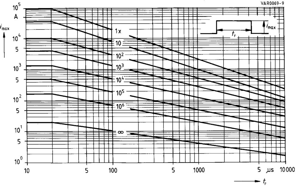
19 Derating Curves Maximum surge current i max = f (t r, pulse train) Derating Curves SIOV-CN0603M4G K14G SIOV-CN0805M4G Siemens Matsushita Components 175
20 Derating Curves Maximum surge current i max = f (t r, pulse train) SIOV-CN0805M6G K17G SIOV-CN0805S14BAUTOG SIOV-CN1206K35G K60G SIOV-CN0805K20G K25G 176 Siemens Matsushita Components
21 Derating Curves Maximum surge current i max = f (t r, pulse train) SIOV-CN1206M4G SIOV-CN1206M6G K30G SIOV-CN1206S14BAUTOG SIOV-CN1210K50G K60G Siemens Matsushita Components 177
22 Derating Curves Maximum surge current i max = f (t r, pulse train) SIOV-CN1210M4G SIOV-CN1210K35G K40G SIOV-CN1812S95AG2 SIOV-SR1210M4S SIOV-CN1210M6G SIOV-CN1210K25G K30G SIOV-SR1210M6S 178 Siemens Matsushita Components
23 Derating Curves Maximum surge current i max = f (t r, pulse train) SIOV-CN1210L8G K20G SIOV-CN1812K50G K60G SIOV-CN1812S60AG SIOV-CN1210S14BAUTOG SIOV-SR1210L8S SIOV-SR1210S14BAUTOS SIOV-CN1812M4G M6G SIOV-CN1812K35G K40G Siemens Matsushita Components 179
24 Derating Curves Maximum surge current i max = f (t r, pulse train) SIOV-CN1812L8G K30G SIOV-CN1812S14BAUTOG SIOV-SR1812S14BAUTOS SHCV-SR1 X/Z SIOV-CN2220K50G K60G 180 Siemens Matsushita Components
25 Derating Curves Maximum surge current i max = f (t r, pulse train) SIOV-CN2220M4G SIOV-CN2220K35G K40G SIOV-SR2220M4S SIOV-CN2220M6G K30G SIOV-CN2220S14BAUTOG SIOV-CN2220K30AUTOG SIOV-SR2220M6S L8S SIOV-CN2220S14BAUTOE2G2 SIOV-SR2220S14BAUTOS SHCV-SR2 X/Z Siemens Matsushita Components 181
 SIOV-S05K11 K40 SIOV-CU3225K11G2 K40G2")

26 Derating Curves Maximum surge current i max = f (t r, pulse train) SIOV-S05K11 K40 SIOV-CU3225K11G2 K40G2 SIOV-CU3225K14AUTOG2 K30AUTOG2 SIOV-S07K11 K40 SIOV-S07K14AUTOS2D1 SIOV-CU4032K11G2 K40G2 SIOV-CU4032K14AUTOG2 K30AUTOG2 182 Siemens Matsushita Components
 SIOV-S05K50 K460 SIOV-CU3225K50G2 K300G2")

27 Derating Curves Maximum surge current i max = f (t r, pulse train) SIOV-S05K50 K460 SIOV-CU3225K50G2 K300G2 SIOV-S07K50 K460 SIOV-S07S60AGS2/95AGS2 SIOV-CU4032K50G2 K300G2 SIOV-CU4032S60AG2/S95AG2 Siemens Matsushita Components 183
 SIOV-S10K11 K40")

28 Derating Curves Maximum surge current i max = f (t r, pulse train) SIOV-S10K11 K40 SIOV-S10K14AUTO K17AUTO SIOV-S10K14AUTOS5D1 SIOV-S10K50 K Siemens Matsushita Components
 SIOV-S10K385 K680")

29 Derating Curves Maximum surge current i max = f (t r, pulse train) SIOV-S10K385 K680 SIOV-S14K11 K40 SIOV-S14K14AUTO K30AUTO SIOV-S14K14AUTOS5D1 Siemens Matsushita Components 185

30 Derating Curves Maximum surge current i max = f (t r, pulse train) SIOV-S14K50 K320 SIOV-S14K130E2 K320E2 186 Siemens Matsushita Components
 SIOV-S14K385")

31 Derating Curves Maximum surge current i max = f (t r, pulse train) SIOV-S14K385 K1000 SIOV-S20K11 K40 SIOV-S20K14AUTO K30AUTO Siemens Matsushita Components 187
 SIOV-S20K50")

32 Derating Curves Maximum surge current i max = f (t r, pulse train) SIOV-S20K50 K115 SIOV-S20K130 K320 SIOV-S20S130BR7 S275BR7 188 Siemens Matsushita Components

33 Derating Curves Maximum surge current i max = f (t r, pulse train) SIOV-S20K130E2 K150E2 SIOV-S20K385 K460 Siemens Matsushita Components 189
 SIOV-S20K510 K1000 190 Siemens Matsushita Components")
34 Derating Curves Maximum surge current i max = f (t r, pulse train) SIOV-S20K510 K Siemens Matsushita Components


35 Derating Curves Maximum surge current i max = f (t r, pulse train) SIOV-B32K130 K150 SIOV-B32K230 K460 Siemens Matsushita Components 191
 SIOV-B32K550")

36 Derating Curves Maximum surge current i max = f (t r, pulse train) SIOV-B32K550 K750 SIOV-B40K75 K150 SIOV-LS40K130QP K150QP 192 Siemens Matsushita Components
 SIOV-B40K230 K460")

37 Derating Curves Maximum surge current i max = f (t r, pulse train) SIOV-B40K230 K460 SIOV-LS40K230QP K460QP SIOV-B40K550 K750 SIOV-LS40K550QP K750QP Siemens Matsushita Components 193


38 Derating Curves Maximum surge current i max = f (t r, pulse train) SIOV-B60K130 K150 SIOV-B60K230 K Siemens Matsushita Components
")
39 Derating Curves Maximum surge current i max = f (t r, pulse train) FRAME4/home/SMC-Archiv-DB/GG-KB-engl/DB-SIOV_97_BNR-B462-P6214-X-X-7600/Derating SIOV-B60K550 K1000 SIOV-B80K130 K1100 Siemens Matsushita Components 195

40 S+M COMPONENTS Siemens Matsushita Components Ferrites and inductive components in modern office counications The little things that do so much In the multimedia age, ferrites and inductive components often play a key role. In the switch-mode power supplies of PCs ETD cores ensure interference-free transmission of power. Ring and E cores in energysaving lamps provide pleasant lighting. Interface transformers in ISDN systems satisfy the high demands of CCITT standards. And ultra-flat planar transformers supply units and installations with the necessary power. For application-specific products and inductive components design you can count on the support of our I.F.C. KNOW-HOW CENTER, right from the initial engineering phase. SCS dependable, fast and competent
41 V/I Characteristics v = f (i) A = Leakage current for worst-case B = Protection level varistor tolerances V/I Characteristics SIOV-CN0603M4G K14G Siemens Matsushita Components 197
42 V/I Characteristics v = f (i) A = Leakage current for worst-case B = Protection level varistor tolerances SIOV-CN0805M4G K25G 198 Siemens Matsushita Components
43 V/I Characteristics v = f (i) A = Leakage current for worst-case B = Protection level varistor tolerances SIOV-CN1206M4G K60G Siemens Matsushita Components 199
44 V/I Characteristics v = f (i) A = Leakage current for worst-case B = Protection level varistor tolerances SIOV-CN1210M4G K60G SIOV-SR1210M4S, M6S, L8S 200 Siemens Matsushita Components
45 V/I Characteristics v = f (i) A = Leakage current for worst-case B = Protection level varistor tolerances SIOV-CN1812M4G K60G SHCV-SR1K20M X/Z 1812 =^ Siemens Matsushita Components 201
46 V/I Characteristics v = f (i) A = Leakage current for worst-case B = Protection level varistor tolerances SIOV-CN2220M4G K60G SHCV-SR2K20M X/Z =^ 2220 SIOV-CN2220K30AUTOG SIOV-SR2220M4S, M6S, L8S 202 Siemens Matsushita Components
47 V/I Characteristics v = f (i) A = Leakage current for worst-case B = Protection level varistor tolerances SIOV-CN0805S14BAUTOG CN2220S14BAUTOG SIOV-CN2220S14BAUTOE2G2 SIOV-SR1210S14BAUTOS SR2220S14BAUTOS SHCV-SR1S14B X/Z =^ 1812 SHCV-SR2S14B X/Z =^ 2220 Siemens Matsushita Components 203
48 V/I Characteristics v = f (i) A = Leakage current for worst-case B = Protection level varistor tolerances SIOV-S05 SIOV-CU3225 (AUTO)G2 204 Siemens Matsushita Components
49 V/I Characteristics v = f (i) A = Leakage current for worst-case B = Protection level varistor tolerances SIOV-S07 (D1) SIOV-CU4032 (AUTO)G2 Siemens Matsushita Components 205
 (D1) 206 Siemens")
50 V/I Characteristics v = f (i) A = Leakage current for worst-case B = Protection level varistor tolerances FRAME4/home/SMC-Archiv-DB/GG-KB-engl/DB-SIOV_97_BNR-B462-P6214-X-X-7600/Kennlinien SIOV-S10 (AUTO) (D1) 206 Siemens Matsushita Components
51 V/I Characteristics v = f (i) A = Leakage current for worst-case B = Protection level varistor tolerances SIOV-S14 (AUTO) (D1) SIOV-S14 (E2) Siemens Matsushita Components 207
52 V/I Characteristics v = f (i) A = Leakage current for worst-case B = Protection level varistor tolerances SIOV-S20 (AUTO) SIOV-S20 (E2) 208 Siemens Matsushita Components
53 V/I Characteristics v = f (i) A = Leakage current for worst-case B = Protection level varistor tolerances FRAME4/home/SMC-Archiv-DB/GG-KB-engl/DB-SIOV_97_BNR-B462-P6214-X-X-7600/Kennlinien SIOV-S20S130BR7 S275BR7 Siemens Matsushita Components 209
54 V/I Characteristics v = f (i) A = Leakage current for worst-case B = Protection level varistor tolerances SIOV-B32K130 K Siemens Matsushita Components
55 V/I Characteristics v = f (i) A = Leakage current for worst-case B = Protection level varistor tolerances SIOV-B40K75 K750 SIOV-LS40K130QP K750QP Siemens Matsushita Components 211
56 V/I Characteristics v = f (i) A = Leakage current for worst-case B = Protection level varistor tolerances SIOV-B60K130 K Siemens Matsushita Components
57 V/I Characteristics v = f (i) A = Leakage current for worst-case B = Protection level varistor tolerances FRAME4/home/SMC-Archiv-DB/GG-KB-engl/DB-SIOV_97_BNR-B462-P6214-X-X-7600/Kennlinien SIOV-B80K130 K1100 Siemens Matsushita Components 213
SIOV Metal Oxide Varistors Leaded Varistors (StandarD Series)
") Leaded Varistors () Disk varistors StandarD series, dimensions Construction Round varistor element, leaded Coating: epoxy resin, flame-retardant to UL 94 V-0 Terminals: tinned copper wire Features Wide
Leaded Varistors () Disk varistors StandarD series, dimensions Construction Round varistor element, leaded Coating: epoxy resin, flame-retardant to UL 94 V-0 Terminals: tinned copper wire Features Wide
Metal Oxide Varistors (MOV) Data Sheet
 Data Sheet") Φ SERIES Metal Oxide Varistors (MOV) Data Sheet Features Wide operating voltage (V ma ) range from 8V to 0V Fast responding to transient over-voltage Large absorbing transient energy capability Low clamping
Φ SERIES Metal Oxide Varistors (MOV) Data Sheet Features Wide operating voltage (V ma ) range from 8V to 0V Fast responding to transient over-voltage Large absorbing transient energy capability Low clamping
Multilayer Chip Capacitors C0G/NP0/CH
 Multilayer Chip Capacitors C0G/NP0/CH Features Good thermal stability High insulation resistance Low dissipation factor Low inductance Applications Resonant circuits Filter circuits Timing elements Coupling
VAR Series Zinc Oxide Varistor
 FEATURES Round Zinc Oxide, leaded Coating: epoxy resin, flame-retardant material Operating Temperature Range: -40 ~+105 Wide operating voltage Approvals: CQ C, UL, VDE RoHS 201165EU; REACH Compliant High
PPA Metallized polypropylene film capacitor MKP - Snubber/pulse - High current
 Main applications Snubber capacitor for energy conversion and control in power semiconductor circuits, protection circuits in SMPSs, induction heaters, high voltage, high current and high pulse applications
C4C-C4H-C4G-C4M MKP Series AXIAL CAPACITORS PCB APPLICATIONS
 C4C-C4H-C4G-C4M AXIAL CAPACITORS PCB APPLICATIONS General characteristics - Self-Healing - Low losses - High ripple current - High contact reliability - Suitable for high frequency applications 40 ±5 L
YJM-L Series Chip Varistor
 Features 1. RoHS & Halogen Free (HF) compliant 2. EIA size: 0402 ~ 2220 3. Operating voltage: 5.5Vdc ~ 85Vdc 4. High surge suppress capability 5. Bidirectional and symmetrical V/I characteristics 6. Multilayer
SMD Transient Voltage Suppressors
 SMD Transient Suppressors Feature Full range from 0 to 22 series. form 4 to 60V RMS ; 5.5 to 85Vdc High surge current ability Bidirectional clamping, high energy Fast response time
Shape Square. Tolerance of Varistor Voltage For Varistor voltage<68, Special For Varistor voltage 68, 10% Lead Wire Type Straight Cut Lead
 Leaded Varistor for urge uppression VP eries Operating Temp. : -40 ~ +85 FEATURE Fast response Excellent clamping ratio, high peak current and pulse energy withstanding characteristics, providing strong
NTC Thermistor:SCK Series
 Features. RoHS & HF compliant 2. Body size: Ф5mm ~ Ф 30mm 3. Radial lead resin coated 4. High power rating 5. Wide resistance range 6. Cost effective 7. Operating temperature range: Φ5mm:-40~+50 Φ8~Φ0mm:-40~+70
Polymer PTC Resettable Fuse: KRG Series
 Features 1. RoHS & Halogen-Free (HF) compliant 2. Radial leaded devices 3. Broadest range of resettable devices available in the industry 4. Hold current ratings from 0.1 to 3.75A 5. Maximum voltage is
B37631 K K 0 60
 Multilayer Ceramic acitors High; X5R and X7R Chip Ordering code system B37631 K 7 5 K 6 Packaging 6 ^ cardboard tape, 18-mm reel 62 ^ blister tape, 18-mm reel Internal coding acitance tolerance K ^ ± %
Specification. code ±1.0 ±1.0 ±1.0 ±1.0 ±0.5 approx (g)
") High CV-value Long Life > 10 years at 50 C Low ESR and ESL High stability, 10 years shelf life Optimized designs available on request RoHS Compliant application Basic design Smoothing, energy storage,
High CV-value Long Life > 10 years at 50 C Low ESR and ESL High stability, 10 years shelf life Optimized designs available on request RoHS Compliant application Basic design Smoothing, energy storage,
Terminal Contact UL Insulation Designation (provided with) style form system approval Flux tight
 style form system approval Flux tight") eatures A miniature PCB Power Relay. form A contact configuration with quick terminal type. 5KV dielectric strength, K surge voltage between coils to contact. Ideal for high rating Home Appliances of heating
eatures A miniature PCB Power Relay. form A contact configuration with quick terminal type. 5KV dielectric strength, K surge voltage between coils to contact. Ideal for high rating Home Appliances of heating
Metal Oxide Varistor:TVR-D Series
 Features. RoHS compliant 2. Halogen-free series are available 3. Body size: Ф7mm ~ Ф 20mm 4. Wide operating voltage range: 5Vac ~ 680Vac 5. High surge current rating up to 3KA 6. High energy rating up
NTC Thermistor:TTC3 Series
 Features. RoHS compliant 2. Halogen-Free(HF) series are available 3. Body size: Ф3mm 4. Radial lead resin coated 5. Operating temperature range: -40 ~+25 6. Wide resistance range 7. Cost effective 8. Agency
NTC Thermistor:SCK Series
 Features. RoHS compliant 2. Body size Ф5mm~ Ф 30mm 3. Radial lead resin coated 4. High power rating 5. Wide resistance range 6. Cost effective 7. Operating temperature range: Φ5mm:-40~+50 Φ8~Φmm:-40~+70
1000 VDC 1250 VDC 125 VAC 250 VAC J K 125 VAC, 250 VAC
 Metallized Polyester Film Capacitor Type: ECQE(F) Non-inductive construction using metallized Polyester film with flame retardant epoxy resin coating Features Self-healing property Excellent electrical
MULTILAYER CHIP VARISTOR JMV S & E Series: (SMD Surge Protection)
") INTRODUCTION Metal Oxide based chip varistors (JMVs) are used for transient suppression. JMVs have non-linear - behavior, which is similar to that of Zener Diode. Each grain in JMV exhibits small p-n junction
INTRODUCTION Metal Oxide based chip varistors (JMVs) are used for transient suppression. JMVs have non-linear - behavior, which is similar to that of Zener Diode. Each grain in JMV exhibits small p-n junction
NTC thermistors for temperature measurement
 NTC thermistors for temperature measurement SMD NTC thermistors with nickel barrier termination, case size 0603 Series/Type: Date: June 2008 EPCOS AG 2008. Reproduction, publication and dissemination of
Metal Oxide Varistor TVR Type
 Features. RoHS compliant 2. Body size Ф5~ Ф 20mm 3. Wide operating voltage range Vac ~ 00Vac 4. Large withstanding surge current capability 0 ~ 6500 (@8/20) 5. Radial lead resin coated 6. Excellent clamping
Metal Oxide Varistor:TVR Series
 Features. RoHS compliant 2. Halogen-free series are available 3. Body size: Ф5 ~ Ф20mm 4. Wide operating voltage range: Vac ~ 00 Vac 5. Operating temperature range: -40 C ~ +85 C Storage temperature range:
Metal Oxide Varistor (MOV) Data Sheet
 Data Sheet") Metal Oxide (MOV) Data Sheet Feature Wide operating voltage range from 82V to 1100V Operating Temperature: -40 ~ +125 Storage Temperature: 15 ~35 Applications The over-voltage protection for transistors,
Metal Oxide (MOV) Data Sheet Feature Wide operating voltage range from 82V to 1100V Operating Temperature: -40 ~ +125 Storage Temperature: 15 ~35 Applications The over-voltage protection for transistors,
Metal Oxide Leaded Film Resistor
 Features -Excellent Long-Time stability -High surge / overload capability -Wide resistance range : 0.1Ω~22MΩ -Controlled temperature coefficient -Resistance standard tolerance: ±5% (consult factory for
NKT NTC Thermistor. Negative Temperature Coefficient Thermistor FEATURES
 FEATURES Large, strong capacity of suppression of inrush current Big material (B value), small residual Small size, Long life, high reliability and fast response APPLICATIONS Switching -supply, switch,
Bulletin 1489 UL489 Circuit Breakers
 Bulletin 489 UL489 Circuit Breakers Tech Data 489-A Standard AC Circuit Breaker 489-D DC Circuit Breaker 489-A, AC Circuit Breakers 489-D, DC Circuit Breakers Bulletin 489-A Industrial Circuit Breaker
Transient Voltage Suppression Diodes: 1.5KE Series Axial Leaded Type 1500 W
 Features 1. Reliable low cost construction utilizing molded plastic technique 2. Both bi-directional and uni-directional devices are available 3. Fast response time 4. Excellent clamping capacity 5. 1500
Metal Oxide Varistor (MOV) Data Sheet
 Data Sheet") Metal Oxide (MOV) Data Sheet Feature Wide operating voltage range from 18V to 1100V Operating Temperature: -40 ~ +105 Storage Temperature: 15 ~35 Applications The over-voltage protection for transistors,
Metal Oxide (MOV) Data Sheet Feature Wide operating voltage range from 18V to 1100V Operating Temperature: -40 ~ +105 Storage Temperature: 15 ~35 Applications The over-voltage protection for transistors,
Metal Oxide Leaded Film Resistor
 SURFACE TEMP. RISE ( ) Power Ratio(%) MOF0623, 0932, 1145, 1550, 1765, 2485 MOF Series Features -Excellent Long-Time stability -High surge / overload capability -Wide resistance range : 0.1Ω~10MΩ -Controlled
Interference Suppression Capacitor
 MOLDED BOX CONSTRUCTION, SUPPRESSION CAPACITOR, RADIAL LEAD FEATURES UL, CSA, VDE, CQC, CE, ENEC APPROVALS X2 SAFETY CAP CLASSIFICATION FOR USE IN ACROSS-THE-LINE APPLICATIONS METALLIZED POLYPROPYLENE
Symbol. Parameter Value Unit. IPP See Next Table A IFSM
 5W Transient Suppressor.5KE-HF Series Stand-off : 6.8 ~ 6V Power Dissipation: 5 Watts RoHS Device Halogen Free Features -Glass passivated chip. -Low leakage. -5W peak pulse power capability with a /μs
Applications. 100GΩ or 1000MΩ μf whichever is less. Rated Voltage Rated Voltage Rated Voltage
 Features Rated Voltage: 100 VAC, 4000VDC Chip Size:,,,,, 2220, 2225 Electrical Dielectric Code EIA IEC COG 1BCG Applications Modems LAN / WAN Interface Industrial Controls Power Supply Back-Lighting Inverter
Transient Voltage Suppressor
 Transient Suppressor Features Glass passivated junction Low incremental surge resistance, excellent clamping capability Underwriters Laboratory Recognition under UL standard for safety 497B: Isolated Loop
NTIC Series. Limiting Inrush Current. NTC Power Thermistor for FEATURES PART NUMBER SYSTEM UL E Ф5~Ф15mm NTIC M S.
 FEATURES UL E223037 Body size: Ф5mm ~ Ф30mm Radial lead resin coated High power rating Wide resistance range Cost effective Operating temperature range: Ф5mm: -40ºC~150ºC Ф8~Ф10mm: -40ºC~170ºC Ф13~Ф30mm:
XKT. Metal Oxide Varistor FEATURES
 FEATURES Operating Temperature Range: -40 ~+105 Body Diameters Range From 5D to 20D Wide Operating from 18V to 1800V Full compliance with RoSH and REH DIMENSION L:16mm min SIZE D MAX H MAX d+-0.05 E c
CSK series. Current Sensing Chip Resistor. Features. Applications. Construction FAITHFUL LINK
 CSK series Current Sensing Chip Resistor Features» 3 Watts power rating in 1 Watt size, 1225 Package» Low TCR of ±100 PPM/ C» Resistance values from 1m to 1 ohm» High purity alumina substrate for high
NTC Thermistor:SCK Series
 Features. RoHS & Halogen Free (HF) compliant 2. Body size: Ф5mm ~ Ф30mm 3. Radial lead resin coated 4. High power rating 5. Wide resistance range 6. Cost effective 7. Operating temperature range: Ф5mm:
NTC Thermistor:SCK Series
 Features. RoHS & Halogen Free (HF) compliant 2. Body size: Ф5mm ~ Ф30mm 3. Radial lead resin coated 4. High power rating 5. Wide resistance range 6. Cost effective 7. Operating temperature range: Ф5mm:
Metal Film Leaded Precision Resistor
 Power ratio(%) MFR Series Features Excellent overall stability Very tight tolerance down to ±0.05% Extremely low TCR down to ±5 PPM/ C High power rating up to 3 Watts Excellent ohmic contact Applications
Current Sensing Chip Resistor SMDL Series Size: 0201/0402/0603/0805/1206/1010/2010/2512/1225/3720/7520. official distributor of
 Product: Current Sensing Chip Resistor SMDL Series Size: 0201/0402/0603/0805/1206/1010/2010/2512/1225/3720/7520 official distributor of Current Sensing Chip Resistor (SMDL Series) 1. Features -3 Watts
2R2. 2 (L W H) [mm] Wire Wound SMD Power Inductor. Nominal Inductance Packing Tape & Reel. Design Code M ±20%
![2R2. 2 (L W H) [mm] Wire Wound SMD Power Inductor. Nominal Inductance Packing Tape & Reel. Design Code M ±20%](/thumbs/78/78109689.jpg "2R2. 2 (L W H) [mm] Wire Wound SMD Power Inductor. Nominal Inductance Packing Tape & Reel. Design Code M ±20%") Wire Wound SMD Power Inductors WPN Series Operating temperature range : -40 ~+125 (Including self-heating) FEATURES Fe base metal material core provides large saturation current Metallization on ferrite
Wire Wound SMD Power Inductors WPN Series Operating temperature range : -40 ~+125 (Including self-heating) FEATURES Fe base metal material core provides large saturation current Metallization on ferrite
Type 947D Polypropylene, High Energy Density, DC Link Capacitors
 Type 947D series uses the most advanced metallized film technology for long life and high reliability in DC Link applications. This series combines high capacitance and very high ripple current capability
CSR series. Thick Film Chip Resistor Current Sensing Type FEATURE PART NUMBERING SYSTEM ELECTRICAL CHARACTERISTICS
 FEATURE Operating Temperature: -55 ~ +155 C 3 Watts power rating in 1 Watt size, 1225 package High purity alumina substrate for high power dissipation Long side terminations with higher power rating PART
4 Way Reversing Valve
 STANDARD 4 Way Reversing Valve SHF series four-way reversing valves are applicable for heat pump systems such as central, unitary and room air conditioners to realize switching between cooling mode and
Data sheet Thick Film Chip Resistor 5% - RS Series 0201/0402/0603/0805/1206
 Data sheet Thick Film Chip Resistor 5% - RS Series 0201/0402/0603/0805/1206 Scope -This specification applies to all sizes of rectangular-type fixed chip resistors with Ruthenium-base as material. Features
Ceramic PTC Thermistor Overload Protection
 FEATURES compliant CPTD type are bare disc type CPTL type are leaded Low, medium and high voltage ratings Low resistance; Small size No need to reset supply after overload No noise generated Stable over
Carbon Film Leaded Resistor
 Features -The most economic industrial investment -Standard tolerance: +/-5% (available +/-2%) -Excellent long term stability -Termination: Standard solder-plated copper lead Applications -Telecommunication
+85 C Snap-Mount Aluminum Electrolytic Capacitors. High Voltage Lead free Leads Rugged Design. -40 C to +85 C
 +85 C Snap-Mount Capacitors FEATURES High ripple Current Ratings Large Case Size Selection Extended Life High Voltage Lead free Leads Rugged Design SPECIFICATIONS Tolerance ±20% at 120Hz, 20 C Operating
PEH C High CV-value Long Life, > 10 years at 50 C Low ESR and ESL High stability, 10 years shelf life
 PEH 169 85 C High CV-value Long Life, > 10 years at 50 C Low ESR and ESL High stability, 10 years shelf life APPLICATION BASIC DESIGN Smoothing, energy storage, or pulse operation in telecommunication
Thin Film Chip Resistors
 FEATURES PRECISE TOLERANCE AND TEMPERATURE COEFFICIENT EIA STANDARD CASE SIZES (0201 ~ 2512) LOW NOISE, THIN FILM (NiCr) CONSTRUCTION REFLOW SOLDERABLE (Pb FREE TERMINATION FINISH) Type Size EIA PowerRating
NTC Thermistor:SCK Series
 Features. RoHS & Halogen Free (HF) compliant 2. Body size: Ф5mm ~ Ф30mm 3. Radial lead resin coated 4. High power rating 5. Wide resistance range 6. Cost effective 7. Operating temperature range: Ф5mm:
Aluminum Electrolytic Capacitors (Large Can Type)
") Aluminum Electrolytic Capacitors (Large Can Type) Snap-In, 85 C TS-U ECE-S (U) Series: TS-U Features General purpose Wide CV value range (33 ~ 47,000 µf/16 4V) Various case sizes Top vent construction
Aluminum Electrolytic Capacitors (Large Can Type) Snap-In, 85 C TS-U ECE-S (U) Series: TS-U Features General purpose Wide CV value range (33 ~ 47,000 µf/16 4V) Various case sizes Top vent construction
Precision Metal Film Fixed Resistor Axial Leaded
 Features EIA standard colour-coding Non-Flame type available Low noise and voltage coefficient Low temperature coefficient range Wide precision range in small package Too low or too high ohmic value can
LR Series Metal Alloy Low-Resistance Resistor
 LR Series Metal Alloy LowResistance Resistor This specification is applicable to lead free, halogen free of RoHS directive for metal alloy lowresistance resistor. The product is for general purpose. The
NTC Thermistor:TSM type
 Features. RoHS compliant 2. EIA size 0402, 0603, 0805, 206 3. Highly reliable structure 4. -40 ~ +25 operating temperature range 5. Wide resistance range 6. Cost effective 7. Agency recognition: UL Recommended
ZNR Transient/Surge Absorbers (Type D)
") ZNR Transient/Surge Absorbers Type: Series: V Features arge withstanding surge current capability in compact sizes arge Energy andling Capability absorbing transient overvoltages in compact sizes ide range
ZNR Transient/Surge Absorbers Type: Series: V Features arge withstanding surge current capability in compact sizes arge Energy andling Capability absorbing transient overvoltages in compact sizes ide range
Multilayer Ceramic Chip Capacitors
 FEATURES X7R, X6S, X5R AND Y5V DIELECTRICS HIGH CAPACITANCE DENSITY ULTRA LOW ESR & ESL EXCELLENT MECHANICAL STRENGTH NICKEL BARRIER TERMINATIONS RoHS COMPLIANT SAC SOLDER COMPATIBLE* PART NUMBER SYSTEM
OWA-60E series IP67. 60W Single Output Moistureproof Adaptor. moistureproof. File Name:OWA-60E-SPEC
 Single Output Moistureproof Adaptor OWA-60E series IP67 Ⅱ Ⅱ moistureproof I File Name:OWA-60E-SPEC 0-04- Single Output Moistureproof Adaptor OWA-60E series SPECIFICATION MODEL OWA-60E- OWA-60E- OWA-60E-0
Current Sensing Thick Film Chip Resistor-SMDB Series Size: 0402/0603/0805/1206/1210/2010/2512. official distributor of
 Product: Current Sensing Thick Film Chip Resistor-SMDB Series Size: 0402/0603/0805/1206/1210/2010/2512 official distributor of Current Sensing Thick Film Chip Resistor-SMDB Series 1. Scope -This specification
NPI Unshielded Power Inductors
 FEATURES NON-SHIELDED MAGNETIC CIRCUIT DESIGN SMALL SIZE WITH CURRENT RATINGS TO 16.5 AMPS SURFACE MOUNTABLE CONSTRUCTION TAKES UP LESS PCB REAL ESTATE AND SAVES MORE POWER TAPED AND REELED FOR AUTOMATIC
Screened electronic cable LiYCY
 Screened electronic cable LiYCY Conductor material: bare copper Conductor class: class 5 = fine stranded Insulation: PVC Screen: copper braid, tinned Screen coverage: 70 % Sheathing material: PVC Flame-retardant:
Polymer PTC Resettable Fuse:KMC Series
 Features 1. RoHS compliant 2. EIA size:1206~1812 3. Hold current ratings from 0.05 to 3A 4. Voltage ratings from 6V computer and electronic applications to 60V 5. Small footprint 6. Fast time to trip 7.
Multilayer Ceramic Chip Capacitors
 FEATURES X7R, X6S, X5R AND Y5V DIELECTRICS HIGH CAPACITANCE DENSITY ULTRA LOW ESR & ESL EXCELLENT MECHANICAL STRENGTH NICKEL BARRIER TERMINATIONS RoHS COMPLIANT SAC SOLDER COMPATIBLE* Temperature Coefficient
MZ0.5GF SERIES ZENER DIODE TECHHICAL SPECIFICATION FEATURES. ABSOLUTE MAXIMUM RATINGE: (Ta=25 ) Parameter Symbols Limits Unit
 Parameter Symbols Limits Unit") MZ.GEV- THRU MZ.GEV-. MZ.GF SERIES MZ.GEV THRU MZ.GEV TECHHICAL SPECIFICATION FEATURES Silicon Planar Power Diodes Standard Voltage Tolerance is ±% DO- Glass Case High Reliability Weight: Approx..g DO-
MZ.GEV- THRU MZ.GEV-. MZ.GF SERIES MZ.GEV THRU MZ.GEV TECHHICAL SPECIFICATION FEATURES Silicon Planar Power Diodes Standard Voltage Tolerance is ±% DO- Glass Case High Reliability Weight: Approx..g DO-
NTC Thermistor:SCK Series
 NTC Thermistor:SCK Series Features. RoHS & Halogen Free (HF) compliant 2. Body size: Ф5mm ~ Ф30mm 3. Radial lead resin coated 4. High power rating 5. Wide resistance range 6. Cost effective 7. Operating
0.5W SMD Zener Diodes TLZJ2.0A TLZJ W SMD Zener Diodes. Features. MiniMelf. Mechanical Data
 Features Planar Die Construction 0.5W Power Dissipation Zener Voltage: 2.0V to 56V Ideally Suited for Automated Assembly Processes RoHS Compliant MiniMelf Mechanical Data Case: Molded Glass MiniMelf Terminals:
Long 3000 hour life at 105 C with high ripple current capability 2 and 3 pin versions available Can vent construction
 TS-HA/HB Series 105 C, 3000 hours Long 3000 hour life at 105 C with high ripple current capability 2 and 3 pin versions available Can vent construction RoHS Compliant Rated Working Voltage: Operating Temperature:
RoHS Y TR. Zero power resistance Max. current Residual resistance Recommend capacitance Part number
 FEATURES Body size: Ф5mm ~ Ф30mm Radial lead resin coated High power rating Wide resistance range Cost effective Operating temperature range: Ф5mm: -40ºC~50ºC Ф8~Ф0mm: -40ºC~70ºC Ф3~Ф30mm: -40ºC~200ºC
Aluminum Electrolytic Capacitors
 Aluminum Electrolytic Capacitors Snap-In, Mini., 105 C, High Ripple APS TS-NH ECE-S (G) Series: TS-NH Features Long life: 105 C 2,000 hours; high ripple current handling ability Wide CV value range (47
RSDW08 & RDDW08 series
 /,, MODEL SELECTION TABLE INPUT ORDER NO. INPUT VOLTAGE (RANGE) NO LOAD INPUT CURRENT FULL LOAD VOLTAGE CURRENT EFFICIENCY (Typ.) CAPACITOR LOAD (MAX.) RSDW08F-03 344mA 3.3V 2000mA 80% 2000μF RSDW08F-05
C121. External Dimensions (L W) (mm) 0603 [0201] [0402] [0603] [0805]
![C121. External Dimensions (L W) (mm) 0603 [0201] [0402] [0603] [0805]](/thumbs/90/101883046.jpg "C121. External Dimensions (L W) (mm) 0603 [0201] [0402] [0603] [0805]") Multilayer Chip SDV Series Operating Temp. : -55 ~+125 FEATURES SMD type suitable for high density mounting Excellent clamping ratio and quick response time (
Multilayer Chip SDV Series Operating Temp. : -55 ~+125 FEATURES SMD type suitable for high density mounting Excellent clamping ratio and quick response time (
Single-channel Safety Barriers Series 9001
 Technical Data Certificates Explosion protection Europe (CENELEC) PTB 01 ATEX 2088 PTB 01 ATEX 2135 (Installation in Zone 2) USA FM Approval 3011002 UL Approval E81680 Canada CSA 1284547 (LR 43394) Russia
Aerovox Corp. Type H High Voltage AC & DC Capacitors. Film Capacitors for Power Electronics Applications. RoHS Compliant. Highlights.
 H Aerovox Corp. Film Capacitors for Power Electronics Applications Specifications Outline Drawing Capacitance Range: AC Voltage Range: DC Voltage Range: Temperature Range: Capacitance Tolerance: Dissipation
Metal thin film chip resistor networks
 Metal thin film chip resistor networks AEC-Q200 Compliant Features Relative resistance and relative TCR definable among multiple resistors within package. Relative resistance : ±%, relative TCR: ±1ppm/
First Sensor Quad APD Data Sheet Part Description QA TO Order #
 Responsivity (/W) First Sensor Quad PD Data Sheet Features Description pplication Pulsed 16 nm laser detection RoHS 211/65/EU Light source positioning Laser alignment ø mm total active area Segmented in
Metal Film Leaded Precision Resistor
 Features Excellent overall stability Very tight tolerance down to ±0.05% Extremely low TCR down to ±5 PPM/ C High power rating up to 3 Watts Excellent ohmic contact Construction Applications Telecommunication
SPBW06 & DPBW06 series
 /,, MODEL SELECTION TABLE INPUT ORDER NO. INPUT VOLTAGE (RANGE) NO LOAD INPUT CURRENT FULL LOAD VOLTAGE CURRENT EFFICIENCY (TYP.) CAPACITOR LOAD (MAX.) SPBW06F-03 310mA 3.3V 0 ~ 1500mA 81% 4700μF SPBW06F-05
LR(-A) Series Metal Alloy Low-Resistance Resistor
 Series Metal Alloy Low-Resistance Resistor") LR(A) Series Metal Alloy LowResistance Resistor This specification is applicable to lead free, halogen free of RoHS directive for metal alloy lowresistance resistor. The product is for general purpose.
LR(A) Series Metal Alloy LowResistance Resistor This specification is applicable to lead free, halogen free of RoHS directive for metal alloy lowresistance resistor. The product is for general purpose.
Screened electronic cable LiYCY
 Screened electronic cable LiYCY conductor material: bare copper conductor construction: fine stranded, class 5 insulation: PVC screen: Cu-braiding screen over strand: Cu-braid, tinned screen coverage:
TSV. Suntan ZINC OXIDE VARISTOR. Operating Temperature Range: -40 ~+85 DIMENSION. T Thickness(max.) L:16mm min
 L:16mm min") Operating Temperature Range: -40 ~+85 DIMENSION L:16mm min SIZE D MAX H MAX d+-0.05 E c max D05 8 11 0.5 5±0.8 2.5 D07 10 12.5 0.5 5±0.8 2.5 D10 13.5 16 0.7 7.5±0.8 2.5 D14 17.5 20 0.7 7.5±0.8 2.5 D20
Operating Temperature Range: -40 ~+85 DIMENSION L:16mm min SIZE D MAX H MAX d+-0.05 E c max D05 8 11 0.5 5±0.8 2.5 D07 10 12.5 0.5 5±0.8 2.5 D10 13.5 16 0.7 7.5±0.8 2.5 D14 17.5 20 0.7 7.5±0.8 2.5 D20
LR Series Metal Alloy Low-Resistance Resistor
 Tel : 881745 Fax : 881749 LR Series Metal Alloy LowResistance Resistor This specification is applicable to lead free, halogen free of RoHS directive for metal alloy lowresistance resistor. The product
NTC Thermistor:SCK Series
 Features. RoHS & Halogen Free (HF) compliant 2. Body size: Ф5mm ~ Ф30mm 3. Radial lead resin coated 4. High power rating 5. Wide resistance range 6. Cost effective 7. Operating temperature range: Ф5mm:
Polymer PTC Resettable Fuse: KMC Series
 Features 1. RoHS & Halogen-Free (HF) compliant 2. IA size: 0603, 0805, 1206, 1812 3. Hold current ratings from 0.05 to 3A 4. Voltage ratings from 6V computer and electronic applications to 60V 5. Small
Multilayer Chip Inductor
 Features -Monolithic structure for high reliability -High self-resonant frequency -Excellent solderability and high heat resistance Construction Applications -RF circuit in telecommunication and other
DATA SHEET Surface mount NTC thermistors. BCcomponents
 DATA SHEET 2322 615 1... Surface mount N thermistors Supersedes data of 17th May 1999 File under BCcomponents, BC02 2001 Mar 27 FEATURES High sensitivity High accuracy over a wide temperature range Taped
Standardized R/T Characteristics
 1 Introduction The R/T characteristics tabulated in the following have been standardized for the resistance value at 25 C. The actual resistance values of a particular NTC thermistor are obtained by multiplying
65W PWM Output LED Driver. IDLV-65 series. File Name:IDLV-65-SPEC
 ~ A File Name:IDLV65SPEC 07050 SPECIFICATION MODEL OUTPUT OTHERS NOTE DC VOLTAGE RATED CURRENT RATED POWER DIMMING RANGE VOLTAGE TOLERANCE PWM FREQUENCY (Typ.) SETUP TIME Note. AUXILIARY DC OUTPUT Note.
RC series Thick Film Chip Resistor
 RC series Thick Film Chip Resistor Features» Small size and light weight» Compatible with wave and reflow soldering» Suitable for lead free soldering» RoHS compliant & Halogen Free Applications Configuration»
Thin Film Precision Chip Resistor (AR Series)
") Construction D1 L (AR Series) Features -Advanced thin film technology -Very tight tolerance down to ±0.01% -Extremely low TCR down to ±5PPM/C -Wide resistance range 1ohm ~ 3Mega ohm -Miniature size 0201
Construction D1 L (AR Series) Features -Advanced thin film technology -Very tight tolerance down to ±0.01% -Extremely low TCR down to ±5PPM/C -Wide resistance range 1ohm ~ 3Mega ohm -Miniature size 0201
60W AC-DC High Reliability Slim Wall-mounted Adaptor. SGA60E series. File Name:SGA60E-SPEC
 AC-DC High Reliability Slim Wall-mounted Adaptor SGA60E series Ⅵ Ⅴ Ⅱ Ⅱ { ψ. ψ File Name:SGA60E-SPEC 2015-09-15 AC-DC High Reliability Slim Wall-mounted Adaptor SGA60E series SPECIFICATION ORDER NO. SGA60E05-P1J
Thin Film Chip Inductor
 Scope -Viking s 0201 and 0402 series inductor is a photo lithographically etched single layer ceramic chip. Viking s design provides high, excellent Q, and superior temperature stability. This highly stable
Negative Temperature Coefficient Thermistor (NTC) Data Sheet
 Data Sheet") Negative Thermistor (NTC Series) Negative Thermistor (NTC) Data Sheet Feature Wide operating voltage range from φ5 to φ20 Style φ5 Φ7/φ9/φ11 Φ13/φ15/φ20-40 ~155-40 ~175-40 ~200 Storage : 15 ~35 Applications
Negative Thermistor (NTC Series) Negative Thermistor (NTC) Data Sheet Feature Wide operating voltage range from φ5 to φ20 Style φ5 Φ7/φ9/φ11 Φ13/φ15/φ20-40 ~155-40 ~175-40 ~200 Storage : 15 ~35 Applications
NTC Thermistor:SCK Type
 Features 1. RoHS compliant 2. Body size Ф5mm~ Ф 30mm 3. Radial lead resin coated 4. High power rating 5. Wide resistance range 6. Cost effective 7. Operating temperature range: Φ5mm:-40~+150 Φ8~Φ10mm:-40~+170
APPLICATIONS TECHNOLOGY. Leaded Discs N.03 N.06 N.09
 NC Disc hermistors ND 03/06/09 NE 03/06/09 NV 06/09 APPLICAIONS ND or NE: Commerical, Industrial and Automotive Applications AEC-Q200 Qualified NV: Professional Applicationsl Alarm and temperature measurement
THICK FILM LEAD FREE CHIP RESISTORS
 Features Suitable for lead free soldering. Compatible with flow and reflow soldering Applications Consumer Electronics Automotive industry Computer Measurement instrument Electronic watch and camera Configuration
QUICKTRONIC PROFESSIONAL QTP5
 osram.com QUICKTRONIC PROFESSIONA QTP5 ECG for T5/ 16mm, T8/ 26mm, DUUX fluorescent lamps QTP5 i.e. UMIUX T5 HO ES 01 Product Features: Up to 100.000 hours lifetime 1 amp start with optimized filament
MZ0.5GN SERIES ZENER DIODE TECHHICAL SPECIFICATION FEATURES. ABSOLUTE MAXIMUM RATINGE: (Ta=25 ) Parameter Symbols Limits Unit
 Parameter Symbols Limits Unit") MZ.GEV- THRU MZ.GEV-. MZ.GN SERIES MZ.GEV THRU MZ.GEV TECHHICAL SPECIFICATION FEATURES Silicon Planar Power Diodes The zener voltages are graded according to the International E standard smaller voltage
MZ.GEV- THRU MZ.GEV-. MZ.GN SERIES MZ.GEV THRU MZ.GEV TECHHICAL SPECIFICATION FEATURES Silicon Planar Power Diodes The zener voltages are graded according to the International E standard smaller voltage
Data sheet Thin Film Chip Inductor AL Series
 Data sheet Thin Film Chip Inductor AL Series Scope - 0201 and 0402 and 0603 series inductor is a photo lithographically etched single layer ceramic chip. This design provides high SRF, excellent Q, and
Sunlord Specifications subject to change without notice. Please check our website for latest information. Revised 2018/04/15
 Wire Wound SMD Power Inductors SPH Series Operating Temp. : -40 ~+125 (Including self-heating) FEATURES Magnetic-resin shielded construction reduces buzz noise to ultra-low levels Metallization on ferrite
THICK FILM CHIP RESISTOR" CAL-CHIP ELECTRONICS INC."
 THICK FILM CHIP RESISTOR CAL-CHIP ELECTRONICS INC. CAL-CHIP SERIES: RM SERIES 1 2 3 INTRODUCTION SCOPE Applies to all sizes of rectangular-type fixed chip resistors with Ruthenium base as material. FEATURES