VRF. Technical Data Book. All indoor units for Europe (R410A, 50Hz, HP/HR)
|
|
|
- Σταύρος Καζαντζής
- 7 χρόνια πριν
- Προβολές:
Transcript
")
1 VRF Technical Data Book All indoor units for Europe (R41A, Hz, HP/HR)
2 History Version Modification Date Remark Ver.1. Release VRF DVM S Indoor Unit TDB for Europe Ver.1.1 Updated heating operation range : HE, HT Ver.1.2 M o dify Electrical wiring diagram of Hydro HE Ver.1.3 Add page index Ver.1.4 Modify Capacity & Power input correction of Hydro HE Ver.1. Modify unit of air flow rate in ERV Plus Ver.1.6 Modification for 'power input' of 1Way Cassette (p.11) Modification for 'Dimensional drawing' of Floor Standing (p.227) Ver Add Temperature and air flow distribution data for console. (p.218~222) Ver.1.7 Ver.1.8 Ver.1.9 Add line up - 1Way Cassette : 2 models (.6/7.1kW) - 36 Cassette : All models (4.~14kW) - Slim Duct (drain pump included) : All models (1.7~14kW) - MSP Duct (drain pump included) : All models (2.2~16kW) - BORACAY : All models (1.~7.1kW) - Console : 2 models (2.2/4.kW) - PAC : All models (14/28kW) Add heat exchanger spec. for all indoor models. Modification for Temperature and air flow distribution data of Big Ceiling. (p.334~33) Add tco2e data (Hydro Unit HT's Specifications) Add Sound Power data & graph (AM28/36/6, p.338, 348)
3 I. II. Products Indoor Units Contents 1. Nomenclature 2. Line up 6 3. Accessory Way Cassette 2Way Cassette 4Way Cassette S(6x6) 4Way Cassette S 36 Cassette Duct S Slim Duct MSP Duct HSP Duct Big Duct OAP Duct Neo Forte AR BORACAY Ceiling Big Ceiling Console Floor Standing PAC ERV Plus Hydro Unit HE Hydro Unit HT 393 3
4 Products 4
5 1 Nomenclature Indoor Units Model Names AM 71 K N 4 D E H EU (1) (2) (3) (4) () (6) (7) (8) Buyer (1) Classification AM VRF (2) Capacity (3) Version F H J K (4) Product Type x 1/1 kw (3 digits) N Indoor Unit (NASA) X Outdoor Unit (NASA) () Product Notation 1 1Way Cassette 2 2Way Cassette 4 4Way Cassette S / 36 Cassette N 4Way Cassette(6x6) L LSP Duct M MSP Duct H HSP Duct E OAP Duct T Neo Forte Q Neo Forte(EEV) A AR V AR(EEV) C Ceiling J Console F Floor Standing P PAC K ERV Plus B Hydro Unit (6) Feature F Flagship P Premium D Deluxe S Standard (7) Rating Voltage E K G (8) Mode H B Heat Pump (R41A) Heat Pump (R134a)
6 2 Line up Indoor unit Model Capacity (kw) JSF- 1Way CST JSF-1 JSF-2 2Way CST 4Way CST 36 CST Floor Standing Unit 4Way CST S (6X6) Duct S (MSP) Slim Duct MSP Duct Ceiling Console Boracay Boracay (with EEV) AR AR (with EEV) 6
7 2 Line up Indoor unit Model Capacity (kw) HSP Duct OAP Duct Big Duct Hydro Unit HE Hydro Unit HT ERV Plus Make sure to use an indoor unit that is compatible with DVM S. If the total capacity of the connected indoor units exceeds the indicated maximum capacity, cooling and heating capacity of the indoor unit may decrease. Total capacity of the connected indoor units can be allowed from % to 13% of the total outdoor unit capacity.. ( Outdoor unit capacity)total capacity of the connected indoor un 1.3 ( Outdoor unit capacity) NOTE You can connect maximum 64 indoor units to the outdoor unit. Maximum quantity of connectable indoor unit is set to 64 since outdoor unit only support up to 64 communication address. Indoor unit address can be assigned from ~63. If the indoor unit address was assigned from 64~79, E21 error will occur. Maximum 32 Wall-mount type indoor units with EEV (AM****NQDEH***, AM****NVDKH***) can be connected. 7
8 3 Accessory Controller Classication Product Model Image Remark Using Wireless Remote Controller MR-EH DVM, CAC Wireless Remote Controller AR-KHE 36 CST Only DVM, CAC Wired Remote Controller MWR-WE11N DVM, CAC Wired Remote Controller - Simple Type MWR-SHN DVM, CAC Wired Remote Controller - Touch Simple Type MWR-SH1N DVM, CAC Individual Control System ERV Wired Remote Controller Wired Remote Controller MWR-VH12N ERV Olny DVM, CAC MWR-WWN EHS Only EHS Receiver KIT MRK-A1N DVM, CAC Zone Controller MWR-ZSN Master controller + Damper controller DVM, CAC Zone Controller MWR-ZS1N Slave controller DVM, CAC Zone Controller MRW-TS External room sensor DVM, CAC 8
9 3 Accessory Controller Classication Product Model Image Remark Using Onoff Controller MCM-A22DN DVM, CAC Touch Centralized Controller MCM-A3N DVM, CAC Centralized Control System WIFI KIT MIM-H3N DVM, CAC Interface Module MIM-N1 DVM, CAC ERV Interface Module MIM-N1 DVM, CAC DMS2. MIM-D1AN DVM, CAC Integrated management System S-NET3 MST-P3P DVM, CAC BACnet Gateway MIM-B17BN DVM, CAC Lonworks Gateway MIM-B18BN DVM, CAC External Contact Interface Module MIM-B14 DVM, CAC Gate Way MTFC (Multi Tenant Function Controller) MCM-C21N DVM SIM (Signal Interface Module) MIM-B12N DVM, CAC PIM (Pulse Interface Module) MIM-B16N DVM, CAC 9
10 3 Accessory Controller Classication Product Model Image Remark Using S-Checker MIM-C1N DVM, CAC Installation /Test run Solution S-Converter MIM-C2N DVM, CAC External Room Sensor MRW-TA DVM, CAC Operation Mode Selection Switch MCM-C2 DVM Others Module Controller MCM-AN CHILLER Only CHILLER FCU Interface Module MIM-F1N CHILLER Only CHILLER NOTE In case you want more information about the accessories, please refer to the control and accessories TDB on pvi.samsung.com site. 1
11 3 Accessory Controller & Control Accessory Compatibility Individual Control System Centralized Control System Integrated management System Gate Way Installation / Test run Solution Others Item NASA (DVM S) Non-NASA (DVM +3/+4) Remark Wireless Remote Controller MR-EH MR-EH DVM, CAC Wireless Remote Controller AR-KHE AR-KHE DVM, CAC (36 CST) Wired Remote Controller MWR-WE11N MWR-WE1 DVM, CAC Wired Remote Controller MWR-SHN MWR-SH DVM, CAC - Simple Type Wired Remote Controller MWR-SH1N - DVM, CAC - Touch Simple Type ERV Wired Remote Controller MWR-VH12N - DVM, CAC (ERV) Wired Remote Controller MWR-WWN MWR-WW EHS Receiver KIT MRK-A1N - DVM, CAC Zone Controller MWR-ZSN MWR-ZS DVM, CAC Zone Controller MWR-ZS1N MWR-ZS1 DVM, CAC Zone Controller MRW-TS MRW-TS DVM, CAC Onoff Controller MCM-A22DN MCM-A22D DVM, CAC Touch Centralized Controller MCM-A3N - DVM, CAC WIFI KIT MIM-H3N MIM-H3 DVM, CAC Interface Module MIM-N1 MIM-N1 DVM, CAC ERV Interface Module MIM-N1 MIM-N1 DVM, CAC DMS2. MIM-D1AN MIM-DA DVM, CAC S-NET3 MST-P3P MST-P3P DVM, CAC BACnet Gateway MIM-B17BN MIM-B17 DVM, CAC Lonworks Gateway MIM-B18BN MIM-B18 DVM, CAC External Contact Interface Module MIM-B14 MIM-B14 DVM, CAC MTFC (Multi Tenant Function MCM-C21N - Controller) SIM (Signal Interface Module) MIM-B12N MIM-B12 DVM, CAC PIM (Pulse Interface Module) MIM-B16N MIM-B16 DVM, CAC Module Controller MCM-AN - CHILLER ONLY FCU KIT MIM-FN - CHILLER ONLY FCU Interface Module MIM-F1N - CHILLER ONLY S-Checker MIM-C1N - DVM, CAC S-Converter MIM-C2N MIM-C2 DVM, CAC External Room Sensor MRW-TA MRW-TA DVM, CAC Operation Mode Selection Switch MCM-C2 MCM-C2 DVM NOTE In case you want to know more information the accessories, please refer to the control and accessories TDB on pvi. samsung.com site 11
12 3 Accessory Piping Product Image Model Remark MXJ-YA19M 1. kw and below MXJ-YA12M Over 1. kw ~ 4. kw and below MXJ-YA2812M Over 4. kw ~ 4. kw and below Y-Joint MXJ-YA281M Over 4. kw ~ 7.3 kw and below MXJ-YA3419M Over 7.3 kw ~ 98.4 kw and below MXJ-YA4119M Over 98.4 kw ~ 13.2 kw and below MXJ-YA4422M Over 13.2 kw Y-Joint (Only H/R) Y-Joint Outdoor Unit MXJ-YA1M MXJ-YAM MXJ-YA31M MXJ-YA38M MXJ-TA3419M MXJ-TA4122M 22.4 kw and below Over 22.4 kw ~ 7.3 kw and below Over 7.3 kw ~ 13.2 kw and below Over 13.2 kw 13.2 kw and below 14.2 kw and Over Y-Joint (Only H/R) Outdoor Unit Distribution Header MCU EEV KIT PDM KIT MXJ-TA31M MXJ-TA38M MXJ-HA12M MXJ-HA311M MXJ-HA3819M MCU-S6NEE1N MCU-S4NEE1N MCU-S4NEE2N MCU-S2NETK1N MEV-E24SA MEV-E32SA MXD-E24K132A MXD-E24K2A MXD-E32K2A MXD-E24K232A MXD-E24K3A MXD-E32K224A MXD-E32K3A MXD-A38K2A MXD-A12K2A MXD-A8K2A 13.2 kw and below 14.2 kw and Over 4. kw and below (for 4 rooms) 7.3 kw and below (for 8 rooms) Over 7.3 kw ~ 13.2 kw and below (for 8 rooms) ~6 kw, ~6 indoor units ~6 kw, ~4 indoor units ~6 kw, ~6 indoor units ~28 kw, ~2 indoor units 1 Indoor 2 Indoor 3 Indoor 8~12 HP 14~16 HP 18~26 HP NOTE In case you want more information about the accessories, please refer to the control and accessories TDB on pvi.samsung.com site. 12
13 3 Accessory Indoor Product Image Model Remark PC1NUSMAN 1Way CST (JSF-1) PC1NUPMAN PC1MWSKAN PC1NWSMAN PC1BWSMAN PC2NUSMEN 1Way CST (JSF-1) (Z-sliding) 1Way CST (JSF-) 1Way CST (JSF-1) 1Way CST (JSF-2) 2Way Cassette Panel PC4SUSMAN PC4SUSMEN PC4NUSKAN PC4NUSKEN PC4NBSKAN 4Way Cassette S (6x6) (Wafe) 4Way Cassette S (6x6) (Classic) 4way Cassette S (Wafe) 4way Cassette S (Classic) 4way Cassette S (Wafe, Black) PC4NUDMAN 36 CST Square (White) PC4NUNMAN 36 CST Circular (White) PC4NBDMAN 36 CST Square (Black) PC4NBNMAN 36 CST Circular (Black) S-Plasma lon KIT MSD-CAN1 MSD-EN1 [Option] 1Way, 4Way, 4Way (6x6), 36, Big Ceiling [Include] Console [Option] Duct S, Big Duct, ERV, ERV Plus Motion detect Sensor MCR-SMA 4Way Cassette S (6x6) 13
 MDP-N47SNC1D HSP Duct (22. / 28. kw) OAP Duct (22.4 / 28. kw) MDP-M7SGU1D MSP- / 1 Duct (9.2 / 11.2 kw) MDP-M7SGU2D MSP-2 Duct (12.8 / 14. kw) HSP Duct (11.2 / 12.8 / 14. kw) MDP-M7SGU3D MSP-S Duct (.")
14 3 Accessory Indoor Product Image Model Remark ERV CO2 Sensor MOS-C1 ERV, ERV PLUS External room sensor MRW-TA Casssette, Wall-mount, Ceiling, Duct, Console MDP-N47SNCD OAP Duct (14. kw) MDP-N47SNC1D HSP Duct (22. / 28. kw) OAP Duct (22.4 / 28. kw) MDP-M7SGU1D MSP- / 1 Duct (9.2 / 11.2 kw) MDP-M7SGU2D MSP-2 Duct (12.8 / 14. kw) HSP Duct (11.2 / 12.8 / 14. kw) MDP-M7SGU3D MSP-S Duct (.6 / 7.1 kw) Drain Pump MDP-E7SEE3D Slim Duct (2.~14. kw) MDP-G7SP Duct S (External, All Capacities) BIG Duct MDP-G7SQ Duct S (Internal, 3. kw~14 kw) BIG Duct MXD-KAN 7. kw~8.7 kw MXD-KAN 14. kw~17. kw AHU KIT MXD-K7AN MXD-K1AN 21. kw~26. kw 28. kw~3. kw 28kW~3kW 6kW~7kW 84kW~1kW 112kW~14kW MXD -A64K1E MCM-D21N MDX-A64K1E X 1 EA MDX-A64K1E X 2 EA MDX-A64K1E X 3 EA MDX-A64K1E X 4 EA NOTE In case you want more information about the accessories, please refer to the control and accessories TDB on pvi.samsung.com site. 14
15 3 Accessory Indoor unit's Accessory Compatibility Product Model Remark JSF- 1way JSF-1 JSF-2 2way 4way 36 4W (6x6) Slim duct MSP-S MSP Duct MSP- MSP-1 MSP-2 Duct-S Big Duct HSP Duct OAP Duct HP 8,1HP RAC Ceiling B-Ceiling Console PAC Floor Standing ERV Plus AHU Panel DRAIN PUMP S-Plasma Ion KIT Motion detect Sensor ERV CO2 Sensor EEV KITS MCU-KIT AHU-KIT PC4NUDMAN Ceiling O PC4NBDMAN Ceiling (Black) O PC4NUNMAN Open O PC4NBNMAN Open (Black) O PC4NUSKAN Wafe O PC4NBSKAN Wafe (Black) O PC4NUSKEN Classic O PC4SUSMAN Wafe O PC4SUSMEN Classic O PC1NUSMAN Stripe O PC1NUPMAN Z-Slide O PC1MWSKAN O PC1NWSMAN Fluid O PC1BWSMAN O PC2NUSMEN Stripe O MDP-N47SNCD - O MDP-N47SNC1D - O O MDP-M7SGU1D - O O MDP-M7SGU2D - O MDP-M7SGU3D - O MDP-E7SEE3D - O MDP-G7SP External, All Capacities O O MDP-G7SQ Internal O O MSD-CAN1 - O O MSD-EAN1 - O MCR-SMA - O MOS-C1 - MEV-E**SA 1 Indoor O MXD-E**K***A 2,3 Indoor O MCU-S6NEE1N Below 6 IDU, below 6 Kw O O O O O O O O O O O O O O O O O O O O O O O MCU-S4NEE1N Below 4 IDU, below 6 kw O O O O O O O O O O O O O O O O O O O O O O O MCU-S4NEE2N Below 2 large capa IDU, below 6 kw O O O O O O O O O O O O O O O O O O O O O O O MCU-S2NEK1N Below 2 IDU, below 28 kw O O O O O O O O O O O O O O O O O O O O O O O MXD-KAN only for 2.Hp's AHU O MXD-KAN only for Hp's AHU O MXD-K7AN only for 7.Hp's AHU O MXD-K1AN only for 1Hp's AHU O MCM-D21N only for 1~4Hp's AHU O O NOTE In case you want to know more information the accessories, please refer to the control and accessories TDB on pvi. samsung.com site 1
16 Indoor units 16
17 1Way Cassette 1 Specifications 2 Capacity Table 3 Dimensional Drawing 4 Electrical Wiring Diagram Sound Pressure Level 6 Sound Power Level 7 Temperature and air flow distribution 17
18 1 Specifications 1Way Cassette Type Model Power Supply Ø, #, V, Hz Mode - Performance Capacity (Nominal) Power Fan Piping Connections Power Input (Nominal) Current Input (Nominal) Motor Air Flow Rate External Pressure Liquid Pipe Gas Pipe Drain Pipe Cooling Heating Cooling Heating Cooling Heating kw Btu/h kw Btu/h W A Type - Output x n w H/M/L (UL) Min/Std/Max CMM I/s mmaq Pa Ø, mm Ø, inch Ø, mm Ø, inch Ø, mm 1Way Cassette 1Way Cassette 1Way Cassette AM17HN1DEH/EU AM22FN1DEH/EU AM22HN1DEH/EU 1,2,22-24, 1,2,22-24, 1,2,22-24, HP/HR HP/HR HP/HR ,8 7, 7, , 8, 8, Crossflow Fan Crossflow Fan Crossflow Fan 27 x 1 17 x 1 27 x / 4.3 / /. / 4..1 / 4.6 / / / / / / / /4" 1/4" 1/4" /2" 1/2" 1/2" VP2 (OD 26,ID 2) VP2 (OD 26,ID 2) VP2 (OD 26,ID 2) Field Wiring Refrigerant Power Source Wire mm² Transmission Cable mm² Type - Control Method R41A R41A R41A EEV(O) EEV(O) EEV(O) Sound Pressure High / Mid / Low db(a) 27 / 24 / / / / / 23 Power Cooling Net Weight Shipping Weight kg kg Dimension Net Dimensions (WxHxD) mm 74 x 13 x x 13 x x 13 x 36 Panel Size Shipping Dimensions (WxHxD) mm Panel model - Panel Net Weight kg Shipping Weight kg Net Dimensions (WxHxD) mm 89 x 223 x 43 1,164 x 212 x x 223 x 43 PC1MWSKAN PC1NUSMAN PC1MWSKAN x x 42 1,18 x x 46 9 x x 42 Shipping Dimensions (WxHxD) Drain Pump mm - / Model 98 x 112 x 482 1,9 x 144 x x 112 x Additional Accessories Drain Pump Max. lifting Height / Displacement mm/liter/h Air Filter * Specifications may be subject to change without prior notice for product improvement. * Mode - HP : Heat Pump, HR : Heat Recovery * Nominal cooling capacities are based on; - Indoor temperature : 27 C DB, 19 C WB - Outdoor temperature : 3 C DB, 24 C WB, Equivalent refrigerant piping : 7.m, Level differences : m * Nominal heating capacities are based on; - Indoor temperature : 2 C DB, 1 C WB - Outdoor temperature : 7 C DB, 6 C WB, Equivalent refrigerant piping : 7.m, Level differences : m * Sound pressure was acquired in an anechoic room. Thus actual noise level may be different depending on the installation conditions. * These products contain R41A which is fluorinated greenhouse gas. 18
19 1 Specifications 1Way Cassette Type Model Power Supply Mode Performance Capacity (Nominal) Power Fan Piping Connections Power Input (Nominal) Current Input (Nominal) Motor Air Flow Rate External Pressure Liquid Pipe Gas Pipe Drain Pipe Cooling Heating Cooling Heating Cooling Heating Ø, #, V, Hz - kw Btu/h kw Btu/h W A Type - Output x n w H/M/L (UL) Min/Std/Max CMM I/s mmaq Pa Ø, mm Ø, inch Ø, mm Ø, inch Ø, mm 1Way Cassette 1Way Cassette AM28FN1DEH/EU AM36FN1DEH/EU 1,2,22-24, 1,2,22-24, HP/HR HP/HR ,6 12, ,9 13, Crossflow Fan Crossflow Fan 17 x 1 17 x 1 7. / 6. /. 8. / 7. / / 1. / / / /4" 1/4" /2" 1/2" VP2 (OD 26,ID 2) VP2 (OD 26,ID 2) Field Wiring Refrigerant Power Source Wire mm² Transmission Cable mm² Type - Control Method R41A R41A EEV(O) EEV(O) Sound Pressure High / Mid / Low db(a) 29 / 27 / 24 3 / 31 / 27 Power Cooling 48 2 Net Weight Shipping Weight kg kg Dimension Net Dimensions (WxHxD) mm 97 x 13 x x 13 x 41 Panel Size Shipping Dimensions (WxHxD) mm Panel model - Panel Net Weight kg Shipping Weight kg Net Dimensions (WxHxD) mm 1,164 x 212 x 478 1,164 x 212 x 478 PC1NUSMAN PC1NUSMAN ,18 x x 46 1,18 x x 46 Shipping Dimensions (WxHxD) Drain Pump mm - / Model 1,9 x 144 x 39 1,9 x 144 x Additional Accessories Drain Pump Max. lifting Height / Displacement mm/liter/h - - Air Filter * Specifications may be subject to change without prior notice for product improvement. * Mode - HP : Heat Pump, HR : Heat Recovery * Nominal cooling capacities are based on; - Indoor temperature : 27 C DB, 19 C WB - Outdoor temperature : 3 C DB, 24 C WB, Equivalent refrigerant piping : 7.m, Level differences : m * Nominal heating capacities are based on; - Indoor temperature : 2 C DB, 1 C WB - Outdoor temperature : 7 C DB, 6 C WB, Equivalent refrigerant piping : 7.m, Level differences : m * Sound pressure was acquired in an anechoic room. Thus actual noise level may be different depending on the installation conditions. * These products contain R41A which is fluorinated greenhouse gas. 19
20 1 Specifications 1Way Cassette Type Model Power Supply Ø, #, V, Hz Mode - Performance Capacity (Nominal) Power Fan Piping Connections Power Input (Nominal) Current Input (Nominal) Motor Air Flow Rate External Pressure Liquid Pipe Gas Pipe Drain Pipe Cooling Heating Cooling Heating Cooling Heating kw Btu/h kw Btu/h W A Type - Output x n w H/M/L (UL) Min/Std/Max CMM I/s mmaq Pa Ø, mm Ø, inch Ø, mm Ø, inch Ø, mm 1Way Cassette 1Way Cassette AM6JN1DEH/EU AM71JN1DEH/EU 1,2,22-24, 1,2,22-24, HP/HR HP/HR ,1 24, , 27, Crossflow Fan Crossflow Fan 4 x 1 4 x / 14. / / 1. / / / / 8.33 / /4" 3/8" /2" /8" VP2 (OD,ID 2) VP2 (OD,ID 2) Field Wiring Refrigerant Power Source Wire mm² Transmission Cable mm² Type - Control Method R41A R41A EEV INCLUDED EEV INCLUDED Sound Pressure High / Mid / Low db(a) 36. / 33. / / 37. / 34. Power Cooling Net Weight Shipping Weight kg kg Dimension Net Dimensions (WxHxD) mm 1,2 x 138 x 4 1,2 x 138 x 4 Panel Size Shipping Dimensions (WxHxD) mm Panel model - Panel Net Weight kg Shipping Weight kg Net Dimensions (WxHxD) mm 1,43 x 224 x 1,43 x 224 x PC1BWSMAN PC1BWSMAN ,41 x 23 x 1,41 x 23 x Additional Accessories Shipping Dimensions (WxHxD) Drain Pump Drain Pump Max. lifting Height / Displacement mm - / Model mm/liter/h 1,474 x 122 x 66 1,474 x 122 x Air Filter * Specifications may be subject to change without prior notice for product improvement. * Mode - HP : Heat Pump, HR : Heat Recovery * Nominal cooling capacities are based on; - Indoor temperature : 27 C DB, 19 C WB - Outdoor temperature : 3 C DB, 24 C WB, Equivalent refrigerant piping : 7.m, Level differences : m * Nominal heating capacities are based on; - Indoor temperature : 2 C DB, 1 C WB - Outdoor temperature : 7 C DB, 6 C WB, Equivalent refrigerant piping : 7.m, Level differences : m * Sound pressure was acquired in an anechoic room. Thus actual noise level may be different depending on the installation conditions. * These products contain R41A which is fluorinated greenhouse gas. 2
21 2 Capacity table 1Way Cassette Cooling Model (*FN*) 2.2(*HN*) Outdoor temperature (ºC, DB) TC : Total Capacity, SHC : Sensible Heat Capacity Indoor temperature (ºC, WB) TC SHC TC SHC TC SHC TC SHC TC SHC TC SHC TC SHC kw kw kw kw kw kw kw kw kw kw kw kw kw kw
22 2 Capacity table 1Way Cassette Cooling Model Outdoor temperature (ºC, DB) TC : Total Capacity, SHC : Sensible Heat Capacity Indoor temperature (ºC, WB) TC SHC TC SHC TC SHC TC SHC TC SHC TC SHC TC SHC kw kw kw kw kw kw kw kw kw kw kw kw kw kw
23 2 Capacity table 1Way Cassette Heating Model (*FN*) 2.2(*HN*) TC : Total Capacity Indoor temperature (ºC, DB) Outdoor temperature (ºC) TC TC TC TC TC DB WB kw kw kw kw kw
24 2 Capacity table 1Way Cassette Heating Model Indoor temperature (ºC, DB) Outdoor temperature (ºC) TC TC TC TC TC DB WB kw kw kw kw kw TC : Total Capacity
25 3 Dimensional drawing 1Way Cassette AM17HN1DEH/EU, AM22HN1DEH/EU
26 3 Dimensional drawing 1Way Cassette AM22FN1DEH/EU, AM28FN1DEH/EU, AM36FN1DEH/EU 26
27 3 Dimensional drawing 1Way Cassette AM6JN1DEH/EU, AM71JN1DEH/EU 27
28 4 Electrical wiring diagram 1Way Cassette AM17HN1DEH/EU, AM22HN1DEH/EU, AM6JN1DEH/EU, AM71JN1DEH/EU NOTE 1. This wiring diagram applies only to the indoor unit. 2. Symbols show as follow; BLK : black, RED : red, BLU : blue, WHT:white, YEL : yellow, BRN : brown, SKY : sky-blue, GRN : green 3. For connection wiring indoor-outdoor transmission F1-F2, indoor-wired remotecontroller transmission F3-F4. 4. : Protective earth(screw), : Connector, n : The wire quantity 28
29 4 Electrical wiring diagram 1Way Cassette AM22FN1DEH/EU, AM28FN1DEH/EU, AM36FN1DEH/EU NOTE 1. This wiring diagram applies only to the indoor unit. 2. Symbols show as follow; BLK : black, RED : red, BLU : blue, WHT:white, YEL : yellow, BRN : brown, SKY : sky-blue, GRN : green 3. For connection wiring indoor-outdoor transmission F1-F2, indoor-wired remotecontroller transmission F3-F4. 4. : Protective earth(screw), : Connector, n : The wire quantity 29
30 Sound pressure level 1Way Cassette 1m Unit: db(a) 1m Model AM17HN1DEH/EU High 27 Low 21 Microphone AM22FN1DEH/EU AM22HN1DEH/EU AM28FN1DEH/EU Note Specifications may be subject to change without prior notice. Sound pressure level is obtained in an anechoic room. Sound pressure level is a relative value, depending on the distance and acoustic environment. Sound pressure level may differ depending on operation condition. dba = A-weighted sound pressure level Reference acoustic pressure db= 2 upa NC curve 1) AM17HN1DEH/EU 2) AM22FN1DEH/EU 4 NC 6 NC 4 4 N C 6 NC 4 Sound pressure level(db) High Low NC 4 NC 3 NC 3 NC NC 2 Sound pressure level(db) High Low NC 4 NC 3 NC 3 NC NC 2 1 NC 1 1 NC Octave band center frequency(hz) Octave band center frequency(hz) 3) AM22HN1DEH/EU 4) AM28FN1DEH/EU 4 NC 6 NC 4 4 N C 6 NC 4 4 NC 4 4 NC 4 Sound pressure level(db) High Low NC 3 NC 3 NC NC 2 Sound pressure level(db) High Low NC 3 NC 3 NC NC 2 1 NC 1 1 NC Octave band center frequency(hz) Octave band center frequency(hz) 3
31 Sound pressure level 1Way Cassette 1m Unit: db(a) 1m Model AM36FN1DEH/EU High 3 Low 27 Microphone AM6JN1DEH/EU AM71JN1DEH/EU Note Specifications may be subject to change without prior notice. Sound pressure level is obtained in an anechoic room. Sound pressure level is a relative value, depending on the distance and acoustic environment. Sound pressure level may differ depending on operation condition. dba = A-weighted sound pressure level Reference acoustic pressure db= 2 upa NC curve 1) AM36FN1DEH/EU 2) AM6JN1DEH/EU 4 NC 6 NC 4 4 NC High NC 4 NC High Mid Low NC 4 NC 3 Sound pressure level(db) Low NC 3 NC NC 2 NC 1 Sound pressure level(db) NC 3 NC NC 2 NC Octave band center frequency(hz) Octave band center frequency(hz) 3) AM71JN1DEH/EU Sound pressure level(db) High Mid Low NC 4 NC 4 NC 3 NC 3 NC NC 2 NC Octave band center frequency(hz) 31
32 6 Sound power level 1Way Cassette 6 4 Note. Specifications may be subject to change without prior notice.. Sound power level is an absolute value that a sound source generates.. dba = A-weighted sound power level.. Reference power : 1pW.. Measured according to ISO )AM17HN1DEH/EU Unit: db(a) Model Power AM17HN1DEH/EU 43 AM22FN1DEH/EU 4 AM22HN1DEH/EU 46 AM28FN1DEH/EU 48 2)AM22FN1DEH/EU 6 4 Sound power level(db) Sound power level(db) Octave band center frequency(hz) Octave band center frequency(hz) 3)AM22HN1DEH/EU 6 4 4)AM28FN1DEH/EU 6 4 Sound power level(db) Sound power level(db) Octave band center frequency(hz) Octave band center frequency(hz) 32
33 6 Sound power level 1Way Cassette 6 4 Note. Specifications may be subject to change without prior notice.. Sound power level is an absolute value that a sound source generates.. dba = A-weighted sound power level.. Reference power : 1pW.. Measured according to ISO )AM36FN1DEH/EU Unit: db(a) Model Power AM36FN1DEH/EU 2 AM6JN1DEH/EU 8 AM71JN1DEH/EU 6 2)AM6JN1DEH/EU 6 4 Sound power level(db) Sound power level(db) Octave band center frequency(hz) Octave band center frequency(hz) 3)AM71JN1DEH/EU 6 4 Sound power level(db) Octave band center frequency(hz) 33
34 7 Temperature and air flow distribution 1 Way Cassette AM36FN1DEH/EU (1) Cooling air velocity distribution Discharge angle : 6º 3 m s Ceiling height.2m/s 2 m 1 m.2m/s m 1 m 2 m 3 m 4 m m 6 m 7 m Floor distance s 8 m (2) Cooling temperature distribution Discharge angle : 6º 3 m Ceiling heigh t 22 2 m 1 m m 1 m 2 m 3 m 4 m m 6 m 7 m Floor distance 8 m (3) Heating air velocity distribution Discharge angle : 6º 3 m s Ceiling height.6m/s 2 m 1 m m 1 m 2 m 3 m 4 m m 6 m 7 m Floor distance 8 m (4) Heating temperature distribution Discharge angle : 6º 3 m Ceiling heigh t 2 m 1 m m 1 m 2 m 3 m 4 m m 6 m 7 m Floor distance 8 m 34
35 7 Temperature and air flow distribution 1 Way Cassette AM6JN1DEH/EU (1) Cooling air velocity distribution Discharge angle : º 2.7 m Ceiling height 2 m 1 m m 1 m 2 m 3 m 4 m m Floor distance (2) Cooling temperature distribution Discharge angle : º Ceiling height m 2 m 1 m m 1 m 2 m 3 m 4 m m Floor distance (3) Heating air velocity distribution Discharge angle : 6º 2.7 m Ceiling height 2 m 1 m m 1 m 2 m 3 m 4 m m Floor distance (4) Heating temperature distribution Discharge angle : 6º m Ceiling height m 1 m m 1 m 2 m 3 m 4 m m Floor distance 3
36 7 Temperature and air flow distribution 1 Way Cassette AM71JN1DEH/EU (1) Cooling air velocity distribution Discharge angle : º 2.7 m Ceiling height 2 m 1 m m 1 m 2 m 3 m 4 m m Floor distance (2) Cooling temperature distribution Discharge angle : º m Ceiling height m 1 m m 1 m 2 m 3 m 4 m m Floor distance (3) Heating air velocity distribution Discharge angle : 6º 2.7 m Ceiling height 2 m 1 m m 1 m 2 m 3 m 4 m m Floor distance (4) Heating temperature distribution Discharge angle : 6º m Ceiling height m 1 m m 1 m 2 m 3 m 4 m m Floor distance 36
37 2Way Cassette 1 Specifications 2 Capacity Table 3 Dimensional Drawing 4 Electrical Wiring Diagram Sound Pressure Level 6 Temperature and air flow distribution 37
38 1) Technical specifications Model AM6FN2DEH AM71FN2DEH Power Supply Ø, #, V, Hz 1, 2, 22-24, 1, 2, 22-24, Mode *1) - HP/HR HP/HR Performance Capacity (Nominal) Power Fan Power Input (Nominal) Current Input (Nominal) Motor Air Flow Rate H/M/L (UL) Cooling *2) kw Btu/h 19,1 24,2 Heating *3) kw Btu/h 21, 27,3 Cooling *2) 7 7 W Heating *3) 7 7 Cooling *2).38.4 A Heating *3).38.4 Type - Crossflow Fan Crossflow Fan Output W Number of unit EA 2 2 CMM 14 / 13 / 12 1 / 14 / 13 l/s /216.67/2../233.33/ mmaq - - External Pressure Min / Std / Max Pa - - WG - - Option Code Piping Connections Field Wiring Refrigerant Sound Liquid Pipe Ø, mm Ø, inch 1/4 3/8 Gas Pipe Ø, mm Ø, inch 1/2 /8 Drain Pipe Ø, mm VP (OD 32,ID ) VP (OD 32,ID ) Power Source Wire Below 2m / over 2m mm 2 1. / / 2. Transmission Cable mm 2.7~1..7~1. Type - R41A R41A Control Method - EEV INCLUDED EEV INCLUDED Sound Pressure High / Mid / Low *4) dba 38 / 37 / 3 41 / 39 / 37 Net Weight kg Shipping Weight kg. 26. Dimensions Net Dimensions (W H D) mm 89 x 23 x 7 89 x 23 x 7 Shipping Dimensions (W H D) mm 1,77 x 299 x 642 1,77 x 299 x 642 Panel Size Additional Accessories Panel model - PC2NUSMEN PC2NUSMEN Panel Net Weight kg Shipping Weight kg Net Dimensions (W H D) mm 13 x x 6 13 x x 6 Shipping Dimensions (W H D) mm 113 x 11 x x 11 x 727 Drain pump - / Model Built-in Built-in Drain pump Max. lifting Height / Displacement mm/liter/h 7 / 24 7 / 24 Air Filter - Long life filter Long life filter * Specifications may be subject to change without prior notice for product improvement. *1) Mode - HP : Heat Pump, HR : Heat Recovery *2) Nominal cooling capacities are based on; - Indoor temperature : 27 C DB, 19 C WB - Outdoor temperature : 3 C DB, 24 C WB, Equivalent refrigerant piping : 7.m, Level differences : m *3) Nominal heating capacities are based on; - Indoor temperature : 2 C DB, 1 C WB - Outdoor temperature : 7 C DB, 6 C WB, Equivalent refrigerant piping : 7.m, Level differences : m *4) Sound pressure was acquired in an anechoic room. Thus actual noise level may be different depending on the installation conditions. 38
39 1) Cooling Model Outdoor temperature (ºC, DB) Indoor temperature (ºC, WB) (ºC, DB) 24 (ºC, WB) TC SHC 3 (ºC, DB) 22 (ºC, WB) TC SHC 28 (ºC, DB) 2 (ºC, WB) TC SHC 27 (ºC, DB) 19 (ºC, WB) TC SHC 26 (ºC, DB) 18 (ºC, WB) TC SHC 23 (ºC, DB) 16 (ºC, WB) TC SHC 2 (ºC, DB) 14 (ºC, WB) TC SHC TC : Total Capacity(kW), SHC : Sensible Heat Capacity(kW) 2) Heating Model Outdoor temperature (ºC) Indoor temperature (ºC, DB) DB WB TC kw 18. TC kw 2. TC kw 22. TC kw 24. TC kw TC : Total Capacity(kW)
40 Suspension bolts(m8~m1) X 4EA No. Name Description.6kW 7.1kW 1 Liquid pipe connection Ø6.3 Flare Ø9.2 Flare 2 Gas pipe connection Ø12.7 Flare Ø1.88 Flare 3 Drain pipe connection VP (OD 32, ID ) 4 Conduit for power supply & communication wiring - Air inlet grille - 6 Air outlet louver - 7 Fresh air intake - 4
41 4 Electrical wiring diagram 2Way Cassette AM6FN2DEH/EU, AM71FN2DEH/EU NOTE 1. This wiring diagram applies only to the indoor unit. 2. Symbols show as follow; BLK : black, RED : red, BLU : blue, WHT:white, YEL : yellow, BRN : brown, SKY : sky-blue, GRN : green 3. For connection wiring indoor-outdoor transmission F1-F2, indoor-wired remotecontroller transmission F3-F4. 4. : Protective earth(screw), : Connector, n : The wire quantity 41
42 Sound pressure level 2Way Cassette Unit: db(a) 1.m Microphone Model AM6FN2DEH/EU AM71FN2DEH/EU High Low 3 37 Note Specifications may be subject to change without prior notice. Sound pressure level is obtained in an anechoic room. Sound pressure level is a relative value, depending on the distance and acoustic environment. Sound pressure level may differ depending on operation condition. dba = A-weighted sound pressure level Reference acoustic pressure db= 2 upa NC curve 1) AM6FN2DEH/EU 2) AM71FN2DEH/EU Sound pressure level (db) Sound pressure level (db) Octave band center frequency(hz) Octave band center frequency(hz) 42
43 6 Temperature and air flow distribution 2Way Cassette AM71FN2DEH/EU (1) Cooling air velocity distribution Discharge angle : 4º 3 m Ceiling height.2m/s.4m/s.8m/s.8m/s.6m/s.6m/s.4m/s.4m/s.4m/s.2m/s 2 m 1 m 4 m 3 m 2 m 1 m m 1 m 2 m 3 m Floor distance 4 m (2) Cooling temperature distribution Discharge angle : 4º ºC 2ºC 2ºC ºC 3 m Ceiling height 24ºC 23ºC 22ºC 21ºC 24ºC 24ºC 21ºC 22ºC 23ºC 24ºC 2 m 1 m 23ºC 23ºC 4 m 3 m 2 m 1 m m 1 m 2 m 3 m Floor distance 4 m (3) Heating air velocity distribution Discharge angle : 4º 3 m.2m/s.2m/s Ceiling height.6m/s.4m/s.8m/s.8m/s.6m/s.4m/s 2 m 1 m.2m/s.2m/s 4 m 3 m 2 m 1 m m 1 m 2 m 3 m Floor distance 4 m (4) Heating temperature distribution Discharge angle : 4º 3 m 33ºC 33ºC Ceiling height ºC 29ºC 27ºC 31ºC 31ºC 29ºC 27ºC ºC 2 m 1 m 23ºC 23ºC 4 m 3 m 2 m 1 m m 1 m 2 m 3 m Floor distance 4 m 43
44 4Way Cassette S(6x6) 1 Specifications 2 Capacity Table 3 Dimensional Drawing 4 Electrical Wiring Diagram Sound Pressure Level 6 Sound Power Level 7 Temperature and air flow distribution 44
45 4
46 46
47 47
48 48
49 2 Cooling Model Outdoor temperature (ºC, DB) TC : Total Capacity, SHC : Sensible Heat Capacity Indoor temperature (ºC, WB) TC SHC TC SHC TC SHC TC SHC TC SHC TC SHC TC SHC kw kw kw kw kw kw kw kw kw kw kw kw kw kw
50 Cooling Model.6 6. Outdoor temperature (ºC, DB) TC : Total Capacity, SHC : Sensible Heat Capacity Indoor temperature (ºC, WB) TC SHC TC SHC TC SHC TC SHC TC SHC TC SHC TC SHC kw kw kw kw kw kw kw kw kw kw kw kw kw kw
51 Heating Model TC : Total Capacity Indoor temperature (ºC, DB) Outdoor temperature (ºC) TC TC TC TC TC DB WB kw kw kw kw kw
52 Heating Model.6 6. TC : Total Capacity Indoor temperature (ºC, DB) Outdoor temperature (ºC) TC TC TC TC TC DB WB kw kw kw kw kw
53 3
54 4 Electrical wiring diagram 4Way Cassette S(6x6) AM1HNNDEH/EU, AM22FNNDEH/EU, AM28FNNDEH/EU, AM36FNNDEH/EU, AM4FNNDEH/EU, AM6FNNDEH/EU, AM6FNNDEH/EU NOTE 1. This wiring diagram applies only to the indoor unit. 2. Symbols show as follow; BLK : black, RED : red, BLU : blue, WHT:white, YEL : yellow, BRN : brown, SKY : sky-blue, GRN : green 3. For connection wiring indoor-outdoor transmission F1-F2, indoor-wired remotecontroller transmission F3-F4. 4. : Protective earth(screw), : Connector, n : The wire quantity 4
55 Sound pressure level 4Way Cassette S (6 x 6) Unit: db(a) Model High Low AM1HNNDEH/EU m AM22FNNDEH/EU 32 Microphone AM28FNNDEH/EU AM36FNNDEH/EU Specifications may be subject to change without prior notice. Sound pressure level is obtained in an anechoic room. Sound pressure level is a relative value, depending on the distance and acoustic environment. Sound pressure level may differ depending on operation condition. dba = A-weighted sound pressure level Reference acoustic pressure db= 2 upa Sound pressure level(db) Sound pressure level(db) Octave band center frequency(hz) Octave band center frequency(hz) Sound pressure level(db) Sound pressure level(db) Octave band center frequency(hz) Octave band center frequency(hz)
56 Sound pressure level 4Way Cassette S (6 x 6) Unit: db(a) Model High Low AM4FNNDEH/EU m AM6FNNDEH/EU Microphone AM6FNNDEH/EU 4 3 Specifications may be subject to change without prior notice. Sound pressure level is obtained in an anechoic room. Sound pressure level is a relative value, depending on the distance and acoustic environment. Sound pressure level may differ depending on operation condition. dba = A-weighted sound pressure level Reference acoustic pressure db= 2 upa NC NC Sound pressure level(db) High Low NC NC 4 NC 4 NC 3 NC 3 NC NC 2 NC 1 Sound pressure level(db) High Low NC NC 4 NC 4 NC 3 NC 3 NC NC 2 NC Octave band center frequency(hz) Octave band center frequency(hz) NC 4 High NC NC 4 Sound pressure level(db) Low NC 4 NC 3 NC 3 NC NC 2 NC Octave band center frequency(hz) 6
57 6 Sound power level 4Way Cassette S (6 x 6) Note. Specifications may be subject to change without prior notice.. Sound power level is an absolute value that a sound source generates.. dba = A-weighted sound power level.. Reference power : 1pW.. Measured according to ISO 3741 Unit: db(a) Model Power AM1HNNDEH/EU 46 AM22FNNDEH/EU 47 AM28FNNDEH/EU AM36FNNDEH/EU Sound power level(db) Sound power level(db) Octave band center frequency(hz) Octave band center frequency(hz) Sound power level(db) Sound power level(db) Octave band center frequency(hz) Octave band center frequency(hz) 7
58 6 Sound power level 4Way Cassette S (6 x 6) Note. Specifications may be subject to change without prior notice.. Sound power level is an absolute value that a sound source generates.. dba = A-weighted sound power level.. Reference power : 1pW.. Measured according to ISO 3741 Unit: db(a) Model Power AM4FNNDEH/EU 3 AM6FNNDEH/EU 6 AM6FNNDEH/EU Sound power level(db) Sound power level(db) Octave band center frequency(hz) Octave band center frequency(hz) 6 4 Sound power level(db) Octave band center frequency(hz) 8
59 7 Temperature and air flow distribution 4Way Cassette S(6x6) AM36FNNDEH/EU (1) Cooling air velocity distribution Discharge angle : 37º 3 m.6m/s.6m/s Ceiling heigh t.4m/s.4m/s 2 m 1 m.2m/s.2m/s 2. m 1. m m 1.m 2. m Floor distance (2) Cooling temperature distribution Discharge angle : 37º 3 m Ceiling heigh t m 1 m 2. m 1. m m 1.m 2. m Floor distance (3) Heating air velocity distribution Discharge angle : 49º 3 m Ceiling heigh t 1.m/s.8m/s.6m/s.4m/s.2m/s 1.m/s.8m/s.6m/s.4m/s.2m/s 2 m 1 m 2. m 1. m m 1.m 2. m Floor distance (4) Heating temperature distribution Discharge angle : 49º 3 m Ceiling heigh t m 1 m m 1. m m 1.m 2. m Floor distance 9
60 7 Temperature and air flow distribution 4Way Cassette S(6x6) AM6FNNDEH/EU (1) Cooling air velocity distribution Discharge angle : 37º 3 m.8m/s.8m/s Ceiling heigh t.4m/s.6m/s.6m/s.4m/s 2 m 1 m.2m/s.2m/s 2. m 1. m m 1.m 2. m Floor distance (2) Cooling temperature distribution Discharge angle : 37º 3 m 2 2 Ceiling heigh t m 1 m 2. m 1. m m 1.m 2. m Floor distance (3) Heating air velocity distribution Discharge angle : 49º 3 m Ceiling heigh t.8m/s.6m/s.4m/s.2m/s.8m/s.6m/s 2 m 1 m 2. m 1. m m 1.m 2. m Floor distance (4) Heating temperature distribution Discharge angle : 49º 3 m Ceiling heigh t m 1 m m 1. m m 1.m 2. m Floor distance 21 6
61 4Way Cassette 1 Specifications 2 Summary Table 3 Capacity Table 4 Dimensional Drawing Center of Gravity 6 Electrical Wiring Diagram 7 Sound data 8 Temperature and Air Flow Distribution 9 Piping Diagram 61
62 1. Specification 4Way Cassette Type 4Way Cassette 4Way Cassette 4Way Cassette 4Way Cassette Power Supply 1,2,22~24, 1,2,22~24, 1,2,22~24, 1,2,22~24, Mode - HP/HR HP/HR HP/HR HP/HR Performance Power exchanger Piping Connections Wiring connections Refrigerant Sound Dimension Capacity Power Input Current Input Current Cooling kw Btu/h 1,4 19,1 24,2 3,7 kw Btu/h 17,1 21, 27,3 34,1 Cooling kw Cooling A MCA A Type - Fin & Tube Fin & Tube Fin & Tube Fin & Tube Material - Al Al Al Al Tube - Cu Cu Cu Cu - Anti-corrosion Anti-corrosion Anti-corrosion Anti-corrosion Type - Turbo Fan Turbo Fan Turbo Fan Turbo Fan Quantity ea m³/min 14. / 13. / / 14. / / 1. / / 18. / 16. l/s 242 / 2 / 28 / 233 / / 8 / / 3 / 27 Model - BLDC Motor BLDC Motor BLDC Motor BLDC Motor W 6 x 1 6 x 1 6 x 1 6 x 1 Liquid Pipe Gas Pipe Type Flare connection Flare connection Flare connection Flare connection /4" 1/4" 3/8" 3/8" Type Flare connection Flare connection Flare connection Flare connection /2" 1/2" /8" /8" Drain Pipe VP (OD 32,ID ) VP (OD 32,ID ) VP (OD 32,ID ) VP (OD 32,ID ) supply Minimum mm Minimum mm with indoor Remark - F1,F2 F1,F2 F1,F2 F1,F2 Type - R41A R41A R41A R41A Control Method - EEV Included EEV Included EEV Included EEV Included Sound Pressure Sound Power / Low Cooling db(a) 33 / 32 / 3 33 / 32 / 3 3 / 34 / / 36 / kg Shipping Weight kg mm 84 x 24 x x 24 x x 24 x x 24 x 84 mm 898 x 27 x x 27 x x 27 x x 27 x
63 1. Specification Type 4Way Cassette 4Way Cassette 4Way Cassette 4Way Cassette Air filter Type - Washable Washable Washable Washable Panel model - PC4NUSKAN PC4NUSKAN PC4NUSKAN PC4NUSKAN kg Shipping Weight kg mm 9 x 4 x 9 9 x 4 x 9 9 x 4 x 9 9 x 4 x 9 mm 1, x 1 x 1, 1, x 1 x 1, x 1 x 1, x 1 x 1, 1, 1, Drain pump - Included Included Included Included mm NOTE Mode : HP(Heat Pump), HR(Heat Recovery) Nominal Cooling : Indoor temperature 27 C DB / 19 C WB, Outdoor temperature 3 C DB/24 C WB, Refrigerant pipe length 7.m, Level difference m. Nominal Heating : Indoor temperature 2 C DB / 1 C WB, Outdoor temperature 7 C DB / 6 C WB, Refrigerant pipe length 7.m, Level difference m. Sound level was acquired in an anechoic room. Thus actual noise level may be different depending on the installation conditions. These products contain R41A which is fluorinated greenhouse gas. Specifications may be subject to change without prior notice. Select wire size based on the value of MCA Drain pump included (check valve included) 63
64 1. Specification Type 4Way Cassette 4Way Cassette 4Way Cassette Power Supply 1,2,22~24, 1,2,22~24, 1,2,22~24, Mode - HP/HR HP/HR HP/HR Performance Power exchanger Piping Connections Wiring connections Refrigerant Sound Dimension Capacity Power Input Current Input Current Cooling kw Btu/h 38,2 43,7 47,8 kw Btu/h 42,7 47,1 4,6 Cooling kw Cooling A MCA A Type - Fin & Tube Fin & Tube Fin & Tube Material - Al Al Al Tube - Cu Cu Cu - Anti-corrosion Anti-corrosion Anti-corrosion Type - Turbo Fan Turbo Fan Turbo Fan Quantity ea m³/min 26. / 24. / / 26. / / 28. / 26. l/s 433 / 4 / / 433 / 383 / 467 / 433 Model - BLDC Motor BLDC Motor BLDC Motor W 6 x 1 97 x 1 97 x 1 Liquid Pipe Gas Pipe Type Flare connection Flare connection Flare connection /8" 3/8" 3/8" Type Flare connection Flare connection Flare connection /8" /8" /8" Drain Pipe VP (OD 32,ID ) VP (OD 32,ID ) VP (OD 32,ID ) supply Minimum mm with indoor Minimum mm Remark - F1,F2 F1,F2 F1,F2 Type - R41A R41A R41A Control Method - EEV Included EEV Included EEV Included Sound Pressure Sound Power / Low Cooling db(a) 4 / 38 / 3 42 / 4 / 3 44 / 41 / kg Shipping Weight kg mm 84 x 246 x x 288 x x 288 x 84 mm 898 x 316 x x 37 x x 37 x
65 1. Specification Type 4Way Cassette 4Way Cassette 4Way Cassette Air filter Type - Washable Washable Washable Panel model - PC4NUSKAN PC4NUSKAN PC4NUSKAN kg Shipping Weight kg mm 9 x 4 x 9 9 x 4 x 9 9 x 4 x 9 mm 1, x 1 x 1, 1, x 1 x 1, 1, x 1 x 1, Drain pump - Included Included Included mm NOTE Mode : HP(Heat Pump), HR(Heat Recovery) Nominal Cooling : Indoor temperature 27 C DB / 19 C WB, Outdoor temperature 3 C DB/24 C WB, Refrigerant pipe length 7.m, Level difference m. Nominal Heating : Indoor temperature 2 C DB / 1 C WB, Outdoor temperature 7 C DB / 6 C WB, Refrigerant pipe length 7.m, Level difference m. Sound level was acquired in an anechoic room. Thus actual noise level may be different depending on the installation conditions. These products contain R41A which is fluorinated greenhouse gas. Specifications may be subject to change without prior notice. Select wire size based on the value of MCA Drain pump included (check valve included) 6
66 2. Summary Table Performance Characteristics Model Code (kg) Cooling (kw) Sensible (Kw) Airflow (CMM) Sound Pressure (dba) Sound Power (dba) High Mid Low High Mid Low High Mid Low High Mid Low High Mid Low High Mid Low High Mid Low Electrical Characteristics Model Power Supply Power Input (W) Current Input (A) MCA (A) 1, 2, 22-24, , 2, 22-24, , 2, 22-24, , 2, 22-24, , 2, 22-24, , 2, 22-24, , 2, 22-24, NOTE MCA : Minimum circuit amperes FLA : Full load amperes 66
67 3. Capacity Table 4Way Cassette Cooling Combination, % (Capacityy index) temperature ( C, DB) TC : Total Capacity (kw), SHC : Sensible Heat Capacity (kw) Indoor temperature ( C, WB) 2 ( C, DB) 23 ( C, DB) 26 ( C, DB) 27 ( C, DB) 28 ( C, DB) 3 ( C, DB) 32 ( C, DB) 16 ( C, WB) 18 ( C, WB) 19 ( C, WB) 2 ( C, WB) 22 ( C, WB) TC TC TC TC TC TC TC
68 3. Capacity Table Combination, % (Capacityy index) temperature ( C, DB) Indoor temperature ( C, WB) 2 ( C, DB) 23 ( C, DB) 26 ( C, DB) 27 ( C, DB) 28 ( C, DB) 3 ( C, DB) 32 ( C, DB) 16 ( C, WB) 18 ( C, WB) 19 ( C, WB) 2 ( C, WB) 22 ( C, WB) TC TC TC TC TC TC TC NOTE Nominal cooling capacities are based on; - Indoor temperature: 27 C DB, 19 C WB - Outdoor temperature: 3 C DB, 24 C WB, Equivalent refrigerant piping: 7.m, Level differences: m Nominal heating capacities are based on; - Indoor temperature: 2 C DB, 1 C WB - Outdoor temperature: 7 C DB, 6 C WB, Equivalent refrigerant piping: 7.m, Level differences: m 68
69 3. Capacity Table Heating Combination, % (Capacityy index) TC : Total Capacity (kw) Indoor temperature ( C, WB) temperature ( C, DB) TC TC TC TC TC DB WB kw kw kw kw kw
70 3. Capacity Table Combination, % (Capacityy index) NOTE Indoor temperature ( C, WB) temperature ( C, DB) TC TC TC TC TC DB WB kw kw kw kw kw Nominal cooling capacities are based on; - Indoor temperature: 27 C DB, 19 C WB - Outdoor temperature: 3 C DB, 24 C WB, Equivalent refrigerant piping: 7.m, Level differences: m Nominal heating capacities are based on; - Indoor temperature: 2 C DB, 1 C WB - Outdoor temperature: 7 C DB, 6 C WB, Equivalent refrigerant piping: 7.m, Level differences: m 7
71 ߦ U ʪ ϑ ͱ ɇ Uθɇи 4 Way Casstte Units : mm [inches] 89~91 [2-11 ~2-11 3/4 ] (Celling opening) 9 [3-1 1/2 ] 73 [2 - ] (Suspension position) Center Line Center Line 24 [9 1/2 ] 27 [1 3/4 ] 3 [11 3/4 ] 31 [1-1 3/4 ] [2 3/8 ][2 3/8 ] ߦ ҩߥ 3 [1/8 ] Space Requirements 11 [4 ] 92. [3 3/4 ] 92. [3 3/4 ] 92. [3 3/4 ] [3 3/4 ] 8 [3 1/4 ] B A 33 [1-1 ] 216 [2 1/8 ] 4 [1 3/4 ] 166 [6 1/2 ] [2 1/8 ] [2-9 ] 1 86 [2 1/8 ] 2 84 [2-9 ] [8 1/2 ] 3 [2 1/8 ] [6 1/2 ] [3 1/2 ] 6 73 [2 - ] (Suspension position) 89~91 [2-11 ~2-11 3/4 ] (Celling opening) 9 [3-1 1/2 ] [3 3/4 ] [3 1/4 ] more 11 ] or 1[4-19. [7 3/4 ] 1 [4-11 ] or mo re 1 [4-11 ] or mo re DETAIL 2 places opposite side more 11 ] or 1[4 - Description A B ĘĮ ߦ 6 7 ~ 9. kw 9. ~ 11.2 kw ߣߣ ߤ ड़ ߣߦ Ǯ Ęɇ ʪ Liquid pipe connection Gas pipe connection Drain pipe connection Conduit for power supply & Communication wiring Air inlet grille Air outlet louver Sub-Duct Description ~.6 kw ߧ ߨ ड़ ߣߦ Ǯ ߦࢩߣ ߧߥ ߨף ɇθʪ ߪࢩߥ ߤߧ ף ɇθʪ ߤࢩߣ ߩ ߤߣף ɇθʪ ߪࢩߧ ߪߪ ߧߣף ɇθʪ VP (OD 32, ID ) 71
72 . Center of Gravity 4 Way Casstte Units : mm [inches] A B D 84 [2-9 ] C 84 [2-9 ] Model A B C D ~ 9. kw 24 [8"] 7 [2 3/4"] 41 [1'-4 1/4"] 36 [1'-2 1/4"] 9. ~ 11.2 kw 246 [9 3/4"] 1 [4"] 41 [1'-4 1/4"] 41 [1'-4 1/4"] 288 [11 1/4"] 13 ["] 42 [1'-4 1/2"] 42 [1'-4 1/2"] 72
73 4Way Cassette Thermistor EVA OUT (1K) Thermistor EVA IN (1K) BLDC Brush Less Dc Motor Thermistor ROOM (1K) NOTE This wiring diagram applies only to the outdoor unit. Symbols show as flow : blk: black, red: red, blu: blue, wht: white, yel: yellow, brn: brown, sky: skyblue, grn: green For connection wiring indoor-outdoor transmission F1-F2, indoor-wired remotecontroller F3-F4. Protective earth(screw) 73
74 7. Sound data 4Way Cassette Sound pressure level Unit: db(a) Model Mid Low m Microphone NR Curve 1) 2) Sound Presure level(db) NR6 NR 4 NR 4 High NR4 3 NR4 3 Mid Low NR3 NR3 2 NR 1 NR2 1 NR1 NR NR NR Sound Presure level(db) NR6 NR 4 NR 4 High NR4 3 NR4 Mid 3 Low NR3 NR3 2 NR 1 NR2 1 NR1 NR NR NR Octave band center frequency(hz) Octave band center frequency(hz) 3) 4) Sound Presure level(db) NR6 NR 4 NR 4 High NR4 3 Mid Low NR4 3 NR3 NR3 2 NR 1 NR2 1 NR1 NR NR NR Sound Presure level(db) NR6 NR 4 High NR 4 Mid NR4 3 Low NR4 3 NR3 NR3 2 NR 1 NR2 1 NR1 NR NR NR Octave band center frequency(hz) Octave band center frequency(hz) NOTE Specifications may be subject to change without prior notice. Sound pressure is obtained in an anechoic room. Sound pressure level is a relative value, depending on the distance and acoustic environment. Sound pressure level may differ depending on operation condition. dba = A weighted sound pressure level 74
75 7. Sound data Unit: db(a) Model Mid Low m Microphone NR Curve ) 6) Sound Presure level(db) NR6 High NR 4 NR 4 Mid NR4 3 Low NR4 3 NR3 NR3 2 NR 1 NR2 1 NR1 NR NR NR Octave band center frequency(hz) Sound Presure level(db) NR6 NR High 4 NR Mid 4 Low NR4 3 NR4 3 NR3 NR3 2 NR 1 NR2 1 NR1 NR NR NR Octave band center frequency(hz) ) Sound Presure level(db) NR6 High NR Mid 4 NR 4 Low NR4 3 NR4 3 NR3 NR3 2 NR 1 NR2 1 NR1 NR NR NR Octave band center frequency(hz) NOTE Specifications may be subject to change without prior notice. Sound pressure is obtained in an anechoic room. Sound pressure level is a relative value, depending on the distance and acoustic environment. Sound pressure level may differ depending on operation condition. dba = A weighted sound pressure level 7
76 7. Sound data 4Way Cassette Sound Power level Unit: db(a) Model Power ) 2) Sound Power level(db) NR9 NR8 NR8 NR7 NR7 NR6 NR6 NR NR NR4 NR4 NR3 NR3 NR NR2 NR1 NR1 NR NR A Sound Power level(db) NR9 NR8 NR8 NR7 NR7 NR6 NR6 NR NR NR4 NR4 NR3 NR3 NR NR2 NR1 NR1 NR NR A Octave band center frequency(hz) Octave band center frequency(hz) 3) 4) Sound Power level(db) NR9 NR8 NR8 NR7 NR7 NR6 NR6 NR NR NR4 NR4 NR3 NR3 NR NR2 NR1 NR1 NR NR A Sound Power level(db) NR9 NR8 NR8 NR7 NR7 NR6 NR6 NR NR NR4 NR4 NR3 NR3 NR NR2 NR1 NR1 NR NR A Octave band center frequency(hz) Octave band center frequency(hz) NOTE Specifications may be subject to change without prior notice. Sound power level is an absolute value that a sound source generates dba = A weighted sound power level Reference power : 1pW Measured according to ISO
77 7. Sound data Unit: db(a) Model Power ) 6) Sound Power level(db) NR9 NR8 NR8 NR7 NR7 NR6 NR6 NR NR NR4 NR4 NR3 NR3 NR NR2 NR1 NR1 NR NR A Sound Power level(db) NR9 NR8 NR8 NR7 NR7 NR6 NR6 NR NR NR4 NR4 NR3 NR3 NR NR2 NR1 NR1 NR NR A Octave band center frequency(hz) Octave band center frequency(hz) 7) Sound Power level(db) NR9 NR8 NR8 NR7 NR7 NR6 NR6 NR NR NR4 NR4 NR3 NR3 NR NR2 NR1 NR1 NR NR A Octave band center frequency(hz) NOTE Specifications may be subject to change without prior notice. Sound power level is an absolute value that a sound source generates dba = A weighted sound power level Reference power : 1pW Measured according to ISO
78 4Way Cassette (1) Cooling air velocity distribution Discharge angle: m 2 m 1 m 2. m 2 m 1 m m 1 m 2 m 2. m (2) Cooling temperature distribution Discharge angle: m 2 m 1 m 2. m 2 m 1 m m 1 m 2 m 2. m (3) Heating air velocity distribution Discharge angle: m 2 m 1 m 2. m 2 m 1 m m 1 m 2 m 2. m (4) Heating temperature distribution Discharge angle: m 2 m 1 m 2. m 2 m 1 m m 1 m 2 m 2. m 78
79 (1) Cooling air velocity distribution Discharge angle: m 2 m 1 m 2.7 m 2 m 1 m m 1 m 2 m 2.7 m (2) Cooling temperature distribution Discharge angle: m 2 m 1 m 2.7 m 2 m 1 m m 1 m 2 m 2.7 m (3) Heating air velocity distribution Discharge angle: m 2 m 1 m 2.7 m 2 m 1 m m 1 m 2 m 2.7 m (4) Heating temperature distribution Discharge angle: m 2 m 1 m 2.7 m 2 m 1 m m 1 m 2 m 2.7 m 79
80 (1) Cooling air velocity distribution Discharge angle: m 2 m 1 m 3.1 m 3 m 2 m 1 m m 1 m 2 m 3 m 3.1 m (2) Cooling temperature distribution Discharge angle: m 2 m 1 m 3.1 m 3 m 2 m 1 m m 1 m 2 m 3 m 3.1 m (3) Heating air velocity distribution Discharge angle: m 2 m 1 m 3.1 m 3 m 2 m 1 m m 1 m 2 m 3 m 3.1 m (4) Heating temperature distribution Discharge angle: m 2 m 1 m 3.1 m 3 m 2 m 1 m m 1 m 2 m 3 m 3.1 m 8
81 (1) Cooling air velocity distribution Discharge angle: 4 2.7m 2 m 1 m 4 m 3 m 2 m 1 m m 1 m 2 m 3 m 4 m (2) Cooling temperature distribution Discharge angle: m 2 m 4 m 3 m 2 m 1 m m 1 m 2 m 3 m 4 m 1 m (3) Heating air velocity distribution Discharge angle: m 2 m 1 m 4 m 3 m 2 m 1 m m 1 m 2 m 3 m 4 m (4) Heating temperature distribution Discharge angle: m 2 m 4 m 3 m 2 m 1 m m 1 m 2 m 3 m 4 m 1 m 81
82 (1) Cooling air velocity distribution Discharge angle: m 2 m 1 m 4 m 3 m 2 m 1 m m 1 m 2 m 3 m 4 m (2) Cooling temperature distribution Discharge angle: m 2 m 1 m 4 m 3 m 2 m 1 m m 1 m 2 m 3 m 4 m (3) Heating air velocity distribution Discharge angle: m 2 m 1 m 4 m 3 m 2 m 1 m m 1 m 2 m 3 m 4 m (4) Heating temperature distribution Discharge angle: m 2 m 1 m 4 m 3 m 2 m 1 m m 1 m 2 m 3 m 4 m 82
83 (1) Cooling air velocity distribution Discharge angle: m 2 m 1 m 4 m 3 m 2 m 1 m m 1 m 2 m 3 m 4 m (2) Cooling temperature distribution Discharge angle: m 2 m 1 m 4 m 3 m 2 m 1 m m 1 m 2 m 3 m 4 m (3) Heating air velocity distribution Discharge angle: m 2 m 1 m 4 m 3 m 2 m 1 m m 1 m 2 m 3 m 4 m (4) Heating temperature distribution Discharge angle: m 2 m 1 m 4 m 3 m 2 m 1 m m 1 m 2 m 3 m 4 m 83
84 4Way Cassette Thermistor - Indoor Room (T-IR) Turbo Fan Heat Exchanger - Indoor unit (HX_ID) Electronic Expansion Valve - Indoor unit (E_IDU) Termistor - IDU Heat Exchanger In (T-II) Filter Electronic Expansion Valve - Indoor unit (E_IDU) Filter Liquid pipe connection port A Gas pipe connection port B Refrigerant flow Cooling Model A B
85 36 Cassette 1 Specifications 2 Capacity Table 3 Dimensional Drawing 4 Electrical Wiring Diagram Sound Pressure Level 6 Sound Power Level 7 Temperature and air flow distribution 8
86 1 Specifications 36 Cassette Type Model Power Supply Ø, #, V, Hz Mode - kw Performance Capacity (Nominal) Power Fan Piping Connections Cooling Btu/h Heating kw Btu/h Power Input Cooling (Nominal) Heating W Current Input Cooling (Nominal) Heating A Motor Type - Output x n w CMM Air Flow Rate H/M/L (UL) I/s External mmaq Pressure Min/Std/Max Pa Ø, mm Liquid Pipe Ø, inch Ø, mm Gas Pipe Ø, inch Drain Pipe Ø, mm 36 Cassette 36 Cassette 36 Cassette 36 Cassette AM4KN4DEH/EU AM6KN4DEH/EU AM71KN4DEH/EU AM9KN4DEH/EU 1,2,22-24, 1,2,22-24, 1,2,22-24, 1,2,22-24, HP/HR HP/HR HP/HR HP/HR ,4 19,1 24,2 3, ,1 21, 27,3 34, Turbo Fan Turbo Fan Turbo Fan Turbo Fan 6 x 1 6 x 1 6 x 1 6 x / 13. / / 14. / / 16. / / 18. / / 2. / / / / / / / /4" 1/4" 3/8" 3/8" /2" 1/2" /8" /8" VP (OD 32,ID ) VP (OD 32,ID ) VP (OD 32,ID ) VP (OD 32,ID ) Field Wiring Refrigerant Sound Power Source Wire mm² Transmission Cable mm² Type - Control Method - Pressure High / Mid / Low Power Net Weight Shipping Weight Cooling db(a) kg kg R41A R41A R41A R41A EEV INCLUDED EEV INCLUDED EEV INCLUDED EEV INCLUDED 33 / 31 / / 32 / / 33 / 3 4 / 36 / Dimension Net Dimensions (WxHxD) mm 947 x 281 x x 281 x x 281 x x 281 x 947 Panel Size Shipping Dimensions (WxHxD) mm Panel model - Panel Net Weight kg Shipping Weight kg Net Dimensions (WxHxD) mm 99 x 33 x x 33 x x 33 x x 33 x 99 PC4NUDMAN PC4NUDMAN PC4NUDMAN PC4NUDMAN , x 66 x 1, 1, x 66 x 1, 1, x 66 x 1, 1, x 66 x 1, Additional Accessories Shipping Dimensions (WxHxD) mm Drain Pump - / Model Drain Pump Max. lifting Height / mm/liter/h Displacement Air Filter - 1,93 x 8 x 1,83 1,93 x 8 x 1,83 1,93 x 8 x 1,83 1,93 x 8 x 1, * Specifications may be subject to change without prior notice. 1) Nominal cooling capacities are based on; - Indoor temperature : 27 C DB, 19 C WB - Outdoor temperature : 3 C DB, 24 C WB, Equivalent refrigerant piping : m, Level differences : m 2) Nominal heating capacities are based on; - Indoor temperature : 2 C DB, 1 C WB - Outdoor temperature : 7 C DB, 6 C WB, Equivalent refrigerant piping : m, Level differences : m 3) Sound pressure was acquired in an anechoic room. Thus actual noise level may be different depending on the installation conditions. 4) These products contain R41A which is fluorinated greenhouse gas. ) Panel type is option. (Ceiling Type/Open Type) About each detail spec, please refer to Dimensional Drawing pages. 86
87 1 Specifications 36 Cassette Type Model Power Supply Ø, #, V, Hz Mode - kw Performance Capacity (Nominal) Power Fan Piping Connections Cooling Btu/h Heating kw Btu/h Power Input Cooling (Nominal) Heating W Current Input Cooling (Nominal) Heating A Motor Type - Output x n w CMM Air Flow Rate H/M/L (UL) I/s External mmaq Pressure Min/Std/Max Pa Ø, mm Liquid Pipe Ø, inch Ø, mm Gas Pipe Ø, inch Drain Pipe Ø, mm 36 Cassette 36 Cassette 36 Cassette AM112KN4DEH/EU AM128KN4DEH/EU AM14KN4DEH/EU 1,2,22-24, 1,2,22-24, 1,2,22-24, HP/HR HP/HR HP/HR ,2 43,7 47, ,7 47,1 4, Turbo Fan Turbo Fan Turbo Fan 97 x 1 97 x 1 97 x 1. / 21. / / 24. / / 26. / / 3. / / 4. / / / /8" 3/8" 3/8" /8" /8" /8" VP (OD 32,ID ) VP (OD 32,ID ) VP (OD 32,ID ) Field Wiring Refrigerant Sound Power Source Wire mm² Transmission Cable mm² Type - Control Method - Pressure High / Mid / Low Power Net Weight Shipping Weight Cooling db(a) kg kg R41A R41A R41A EEV INCLUDED EEV INCLUDED EEV INCLUDED 4 / 36 / / 38 / / 4 / Dimension Net Dimensions (WxHxD) mm 947 x 36 x x 36 x x 36 x 947 Panel Size Shipping Dimensions (WxHxD) mm Panel model - Panel Net Weight kg Shipping Weight kg Net Dimensions (WxHxD) mm 99 x 414 x x 414 x x 414 x 99 PC4NUDMAN PC4NUDMAN PC4NUDMAN , x 66 x 1, 1, x 66 x 1, 1, x 66 x 1, Additional Accessories Shipping Dimensions (WxHxD) mm Drain Pump - / Model Drain Pump Max. lifting Height / mm/liter/h Displacement Air Filter - 1,93 x 8 x 1,83 1,93 x 8 x 1,83 1,93 x 8 x 1, * Specifications may be subject to change without prior notice. 1) Nominal cooling capacities are based on; - Indoor temperature : 27 C DB, 19 C WB - Outdoor temperature : 3 C DB, 24 C WB, Equivalent refrigerant piping : m, Level differences : m 2) Nominal heating capacities are based on; - Indoor temperature : 2 C DB, 1 C WB - Outdoor temperature : 7 C DB, 6 C WB, Equivalent refrigerant piping : m, Level differences : m 3) Sound pressure was acquired in an anechoic room. Thus actual noise level may be different depending on the installation conditions. 4) These products contain R41A which is fluorinated greenhouse gas. ) Panel type is option. (Ceiling Type/Open Type) About each detail spec, please refer to Dimensional Drawing pages. 87
88 2 Capacity table 36 C Cooling Model Outdoor Air Temp. (DB) TC : Total Capacity, SHC : Sensible Heat Capacity Indoor temperature 2 (ºC, DB) 23 (ºC, DB) 26 (ºC, DB) 27 (ºC, DB) 28 (ºC, DB) 3 (ºC, DB) 32 (ºC, DB) 14 (ºC, WB) 16 (ºC, WB) 18 (ºC, WB) 19 (ºC, WB) 2 (ºC, WB) 22 (ºC, WB) 24 (ºC, WB) TC(kW) SHC(kW) TC(kW) SHC(kW) TC(kW) SHC(kW) TC(kW) SHC(kW) TC(kW) SHC(kW) TC(kW) SHC(kW) TC(kW) SHC(kW)
89 2 Capacity table 36 C Cooling Model Outdoor Air Temp. (DB) TC : Total Capacity, SHC : Sensible Heat Capacity Indoor temperature 2 (ºC, DB) 23 (ºC, DB) 26 (ºC, DB) 27 (ºC, DB) 28 (ºC, DB) 3 (ºC, DB) 32 (ºC, DB) 14 (ºC, WB) 16 (ºC, WB) 18 (ºC, WB) 19 (ºC, WB) 2 (ºC, WB) 22 (ºC, WB) 24 (ºC, WB) TC(kW) SHC(kW) TC(kW) SHC(kW) TC(kW) SHC(kW) TC(kW) SHC(kW) TC(kW) SHC(kW) TC(kW) SHC(kW) TC(kW) SHC(kW)
90 2 Capacity table 36 C Heating Model TC : Total Capacity Indoor temperature Outdoor Air Temp. (ºC) 16 (ºC, DB) 18 (ºC, DB) 2 (ºC, DB) 22 (ºC, DB) 24 (ºC, DB) DB WB TC(kW) TC(kW) TC(kW) TC(kW) TC(kW)
91 2 Capacity table 36 C Heating Model TC : Total Capacity Indoor temperature Outdoor Air Temp. (ºC) 16 (ºC, DB) 18 (ºC, DB) 2 (ºC, DB) 22 (ºC, DB) 24 (ºC, DB) DB WB TC(kW) TC(kW) TC(kW) TC(kW) TC(kW)
92 3 Dimensional drawing 36 C AM4KN4DEH/, AM6KN4DEH/, AM71KN4DEH/, AM9KN4DEH/ 92
93 3 Dimensional drawing 36 C AM112KN4DEH/, AM128KN4DEH/ AM14KN4DEH/ 93
94 3 Dimensional drawing 36 C AM4KN4DEH/EU, AM6KN4DEH/EU, AM71KN4DEH/EU, AM9KN4DEH/EU 4.The circular panel is by default available in exposed installation.. Make inspection holes on the ceiling for easier installation and maintenance, as shown in the following table. (The size of an inspection hole must be at least 4 mm x 4 mm.) 6. A suspended ceiling structure can substitute for the inspection holes. Category Square panel Circular panel Inspection hole Recessed installation Integrated Suspended 1 ea 2 ea - Exposed installation 94
95 3 Dimensional drawing 36 C AM112KN4DEH/EU, AM128KN4DEH/EU, AM14KN4DEH/EU 4.The circular panel is by default available in exposed installation.. Make inspection holes on the ceiling for easier installation and maintenance, as shown in the following table. (The size of an inspection hole must be at least 4 mm x 4 mm.) 6. A suspended ceiling structure can substitute for the inspection holes. Category Square panel Circular panel Inspection hole Recessed installation Integrated Suspended 1 ea 2 ea - Exposed installation 9
96 4 Electrical wiring diagram 36 Cassette AM4KN4DEH/EU, AM6KN4DEH/EU, AM71KN4DEH/EU, AM9KN4DEH/EU, AM112KN4DEH/EU, AM128KN4DEH/EU, AM14KN4DEH/EU NOTE 1. This wiring diagram applies only to the indoor unit. 2. Symbols show as follow; BLK : black, RED : red, BLU : blue, WHT:white, YEL : yellow, BRN : brown, SKY : sky-blue, GRN : green 3. For connection wiring indoor-outdoor transmission F1-F2, indoor-wired remotecontroller transmission F3-F4. 4. : Protective earth(screw), : Connector, n : The wire quantity 96
97 Sound pressure level 36 Cassette Unit: db(a) Model High Low AM4KN4DEH/EU AM6KN4DEH/EU AM71KN4DEH/EU 36 3 AM9KN4DEH/EU 4 32 Note Specifications may be subject to change without prior notice. Sound pressure level is obtained in an anechoic room. Sound pressure level is a relative value, depending on the distance and acoustic environment. Sound pressure level may differ depending on operation condition. dba = A-weighted sound pressure level Reference acoustic pressure db= 2 upa NC curve 1) AM4KN4DEH/EU 7 2) AM6KN4DEH/EU 7 6 NC 6 NC 6 6 NC 6 NC 6 Sound pressure level(db) High Low NC NC NC 4 NC 4 NC 3 NC 3 NC NC 2 Sound pressure level(db) High Low NC NC NC 4 NC 4 NC 3 NC 3 NC NC 2 1 NC 1 1 NC Octave band center frequency(hz) Octave band center frequency(hz) 3) AM71KN4DEH/EU 7 4) AM9KN4DEH/EU 7 6 NC 6 NC 6 6 NC 6 NC 6 Sound pressure level(db) High Low NC NC NC 4 NC 4 NC 3 NC 3 NC NC 2 Sound pressure level(db) High Low NC NC NC 4 NC 4 NC 3 NC 3 NC NC 2 1 NC 1 1 NC Octave band center frequency(hz) Octave band center frequency(hz) 97
98 Sound pressure level 36 Cassette Unit: db(a) Model High Low AM112KN4DEH/EU 4 32 AM128KN4DEH/EU AM14KN4DEH/EU 44 3 Note Specifications may be subject to change without prior notice. Sound pressure level is obtained in an anechoic room. Sound pressure level is a relative value, depending on the distance and acoustic environment. Sound pressure level may differ depending on operation condition. dba = A-weighted sound pressure level Reference acoustic pressure db= 2 upa NC curve 1) AM112KN4DEH/EU 7 2) AM128KN4DEH/EU 7 6 NC 6 NC 6 6 NC 6 NC 6 Sound pressure level(db) High Low NC NC NC 4 NC 4 NC 3 NC 3 NC NC 2 Sound pressure level(db) High Low NC NC NC 4 NC 4 NC 3 NC 3 NC NC 2 1 NC 1 1 NC Octave band center frequency(hz) Octave band center frequency(hz) 3) AM14KN4DEH/EU 7 Sound pressure level(db) High Low NC 6 NC 6 NC NC NC 4 NC 4 NC 3 NC 3 NC NC 2 NC Octave band center frequency(hz) 98
99 6 Sound power level 36 Cassette Note. Specifications may be subject to change without prior notice.. Sound power level is an absolute value that a sound source generates.. dba = A-weighted sound power level.. Reference power : 1pW.. Measured according to ISO 3741 Unit: db(a) Model Power AM4KN4DEH/EU AM6KN4DEH/EU 1 AM71KN4DEH/EU 3 AM9KN4DEH/EU 7 1)AM4KN4DEH/EU 2)AM6KN4DEH/EU Cooling Cooling Sound power level(db) 4 3 Sound power level(db) A A Octave band center frequency(hz) Octave band center frequency(hz) 3)AM71KN4DEH/EU 4)AM9KN4DEH/EU Cooling 6 Cooling Sound power level(db) 4 3 Sound power level(db) A A Octave band center frequency(hz) Octave band center frequency(hz) 99
100 6 Sound power level 36 Cassette Note. Specifications may be subject to change without prior notice.. Sound power level is an absolute value that a sound source generates.. dba = A-weighted sound power level.. Reference power : 1pW.. Measured according to ISO 3741 Unit: db(a) Model Power AM112KN4DEH/EU 8 AM128KN4DEH/EU 6 AM14KN4DEH/EU 61 1)AM112KN4DEH/EU 2)AM128KN4DEH/EU Cooling 6 Cooling Sound power level(db) 4 3 Sound power level(db) A A Octave band center frequency(hz) Octave band center frequency(hz) 3)AM14KN4DEH/EU 7 6 Cooling Sound power level(db) A Octave band center frequency(hz) 1
101 7 Temperature and air flow distribution 36 C AM4KN4DEH/EU (1) Cooling air velocity distribution Discharge angle : 6º (2) Cooling temperature distribution Discharge angle : 6º (3) Heating air velocity distribution Discharge angle : 6º (4) Heating temperature distribution Discharge angle : 6º 11
102 7 Temperature and air flow distribution 36 C AM6KN4DEH/EU (1) Cooling air velocity distribution Discharge angle : 6º (2) Cooling temperature distribution Discharge angle : 6º (3) Heating air velocity distribution Discharge angle : 6º (4) Heating temperature distribution Discharge angle : 6º 12
103 7 Temperature and air flow distribution 36 C AM71KN4DEH/EU (1) Cooling air velocity distribution Discharge angle : 6º (2) Cooling temperature distribution Discharge angle : 6º (3) Heating air velocity distribution Discharge angle : 6º (4) Heating temperature distribution Discharge angle : 6º 13
104 7 Temperature and air flow distribution 36 C AM9KN4DEH/EU (1) Cooling air velocity distribution Discharge angle : 6º (2) Cooling temperature distribution Discharge angle : 6º (3) Heating air velocity distribution Discharge angle : 6º (4) Heating temperature distribution Discharge angle : 6º 14
105 7 Temperature and air flow distribution 36 C AM112KN4DEH/EU (1) Cooling air velocity distribution Discharge angle : 6º (2) Cooling temperature distribution Discharge angle : 6º (3) Heating air velocity distribution Discharge angle : 6º (4) Heating temperature distribution Discharge angle : 6º 1
106 7 Temperature and air flow distribution 36 C AM128KN4DEH/EU (1) Cooling air velocity distribution Discharge angle : 6º (2) Cooling temperature distribution Discharge angle : 6º (3) Heating air velocity distribution Discharge angle : 6º (4) Heating temperature distribution Discharge angle : 6º 16
107 7 Temperature and air flow distribution 36 C AM14KN4DEH/EU (1) Cooling air velocity distribution Discharge angle : 6º (2) Cooling temperature distribution Discharge angle : 6º (3) Heating air velocity distribution Discharge angle : 6º (4) Heating temperature distribution Discharge angle : 6º 17
108 Duct S 1 Specification 2 Summary Table 3 Capacity Table 4 Dimensional Drawing Center of Gravity 6 Electrical Wiring Diagram 7 Sound data 8 Fan Characteristics 9 Piping Diagram 18
109 1. Specification Duct S Model CODE AM36HNMPKH/EU AM4HNMPKH/EU AM6HNMPKH/EU Power Supply 1,2,22~24, 1,2,22~24, 1,2,22~24, Mode - HP/HR HP/HR HP/HR Performance kw Cooling (ISO/SASO) Capacity Btu/h 12,3 1,4 19,1 (Nominal) kw Heating Btu/h 13,6 17,1 21, Power Input Cooling 6 7 W (Nominal) Heating 6 7 Power Current Input Cooling..6.7 A (Nominal) Heating..6.7 Current MCA A MFA/MOP Type - FME FME FME Heat Fin - Al Al Al Material exchanger Tube - Al Al Al Fin Treatment - Anti-corrosion Anti-corrosion Anti-corrosion Type - Sirocco Fan Sirocco Fan Sirocco Fan Quantity EA Fan Air Flow Rate H/M/L (UL) m³/min 12. / 9. / / 11. / / 13. / 11. l/s 2 / 18 / / 183 / / 2 / 183 External mmaq / 2. / 1 / 3 / 1 / 3 / 1 Min / Std / Max Pressure Pa / 24. / / 29.4 / / 29.4 / Fan Motor Model - BLDC motor(feedback) BLDC motor(feedback) BLDC motor(feedback) Output x n W 13 x 1 13 x 1 13 x 1 Type Flare connection Flare connection Flare connection Liquid Pipe /4" 1/4" 1/4" Piping Connections Wiring connections Refrigerant Sound Dimensions Type Flare connection Flare connection Flare connection Gas Pipe /2" 1/2" 1/2" Heat insulation - Both liquid and gas pipes Both liquid and gas pipes Both liquid and gas pipes Drain Pipe VP (OD 32,ID ) VP (OD 32,ID ) VP (OD 32,ID ) For power supply Minimum mm For connection Minimum mm with indoor Remark - F1,F2 F1,F2 F1,F2 Type - R41A R41A R41A Control Method - EEV Included EEV Included EEV Included Sound Pressure High / Mid / Low 29/26/23 31/28/24 32/29/ db(a) Sound Power Cooling (Nominal) Net Weight kg... Shipping Weight kg Net Dimensions (W H D) mm 8 x x 7 8 x x 7 8 x x 7 Shipping Dimensions (W H D) mm 164 x 32 x x 32 x x 32 x 784 Removable / Washable / Removable / Washable / Removable / Washable / Mildew proof Mildew proof Mildew proof MDP-G7SQ(built-in) MDP-G7SQ(built-in) MDP-G7SQ(built-in) Drain pump Model Drain pump MDP-G7SP(external) MDP-G7SP(external) MDP-G7SP(external) Max. lifting Height mm Air filter Type - Additional Accessories NOTE Mode : HP(Heat Pump), HR(Heat Recovery) Nominal Cooling : Indoor temperature 27ºCDB / 19ºCWB, Outdoor temperature 3ºCDB/24ºCWB, Refrigerant pipe length 7.m, Level difference m. Nominal Heating : Indoor temperature 2ºCDB / 1ºCWB, Outdoor temperature 7ºCDB / 6ºCWB, Refrigerant pipe length 7.m, Level difference m. Sound pressure level was acquired in an anechoic room. Thus actual noise level may be different depending on the installation conditions. These products contain R41A which is fluorinated greenhouse gas. Specifications may be subject to change without prior notice. Select wire size based on the value of MCA 19
110 1. Specification Duct S Model CODE AM71HNMPKH/EU AM9HNMPKH/EU AM112HNMPKH/EU Power Supply 1,2,22~24, 1,2,22~24, 1,2,22~24, Mode - HP/HR HP/HR HP/HR Performance kw Cooling (ISO/SASO) Capacity Btu/h 24,2 3,7 38,2 (Nominal) kw Heating Btu/h 27,3 34,1 42,7 Power Input Cooling W (Nominal) Heating Power Current Input Cooling A (Nominal) Heating Current MCA A MFA/MOP Type - FME FME FME Heat Fin - Al Al Al Material exchanger Tube - Al Al Al Fin Treatment - Anti-corrosion Anti-corrosion Anti-corrosion Type - Sirocco Fan Sirocco Fan Sirocco Fan Quantity EA Fan Air Flow Rate H/M/L (UL) m³/min 22. / 19. / /. / / 29. / 22. l/s 367 / 317 / / 417 / / 483 / 367 External mmaq / 3 / 1 / 4 / 1 /.2 / 1 Min / Std / Max Pressure Pa / 29.4 / / 39.2 / / 1. / Fan Motor Model - BLDC motor(feedback) BLDC motor(feedback) BLDC motor(feedback) Output x n W 13 x 1 13 x x 1 Type Flare connection Flare connection Flare connection Liquid Pipe /8" 3/8" 3/8" Piping Connections Wiring connections Refrigerant Sound Dimensions Type Flare connection Flare connection Flare connection Gas Pipe /8" /8" /8" Heat insulation - Both liquid and gas pipes Both liquid and gas pipes Both liquid and gas pipes Drain Pipe VP (OD 32,ID ) VP (OD 32,ID ) VP (OD 32,ID ) For power supply Minimum mm For connection Minimum mm with indoor Remark - F1,F2 F1,F2 F1,F2 Type - R41A R41A R41A Control Method - EEV Included EEV Included EEV Included Sound Pressure High / Mid / Low 37/33/29 38/3/32 38/3/32 db(a) Sound Power Cooling (Nominal) Net Weight kg Shipping Weight kg Net Dimensions (W H D) mm 8 x x 7 12 x x 7 13 x 3 x 7 Shipping Dimensions (W H D) mm 164 x 32 x x 32 x x 37 x 779 Removable / Washable / Removable / Washable / Removable / Washable / Mildew proof Mildew proof Mildew proof MDP-G7SQ(built-in) MDP-G7SQ(built-in) MDP-G7SQ(built-in) Drain pump Model Drain pump MDP-G7SP(external) MDP-G7SP(external) MDP-G7SP(external) Max. lifting Height mm Air filter Type - Additional Accessories NOTE Mode : HP(Heat Pump), HR(Heat Recovery) Nominal Cooling : Indoor temperature 27ºCDB / 19ºCWB, Outdoor temperature 3ºCDB/24ºCWB, Refrigerant pipe length 7.m, Level difference m. Nominal Heating : Indoor temperature 2ºCDB / 1ºCWB, Outdoor temperature 7ºCDB / 6ºCWB, Refrigerant pipe length 7.m, Level difference m. Sound pressure level was acquired in an anechoic room. Thus actual noise level may be different depending on the installation conditions. These products contain R41A which is fluorinated greenhouse gas. Specifications may be subject to change without prior notice. Select wire size based on the value of MCA 11
111 1. Specification Duct S Model CODE AM128HNMPKH/EU AM14HNMPKH/EU AM112HNHPKH/EU Power Supply 1,2,22~24, 1,2,22~24, 1,2,22~24, Mode - HP/HR HP/HR HP/HR Performance kw Cooling (ISO/SASO) Capacity Btu/h 43,7 47,8 38,2 (Nominal) kw Heating Btu/h 47,1 4,6 42,7 Power Input Cooling W (Nominal) Heating Power Current Input Cooling A (Nominal) Heating Current MCA A MFA/MOP Type - FME FME FME Heat Fin - Al Al Al Material exchanger Tube - Al Al Al Fin Treatment - Anti-corrosion Anti-corrosion Anti-corrosion Type - Sirocco Fan Sirocco Fan Sirocco Fan Quantity EA Fan Air Flow Rate H/M/L (UL) m³/min 38. / 32. /. 42. / 34. /. 3. / 29. / 22. l/s 633 / 33 / / 67 / / 483 / 367 External mmaq /.2 / 1 /.2 / 1 3 / 6.2 / 2 Min / Std / Max Pressure Pa / 1. / / 1. / / 6.8 / Fan Motor Model - BLDC motor(feedback) BLDC motor(feedback) BLDC motor(feedback) Output x n W 244 x x 1 3 x 1 Type Flare connection Flare connection Flare connection Liquid Pipe /8" 3/8" 3/8" Piping Connections Wiring connections Refrigerant Sound Dimensions Type Flare connection Flare connection Flare connection Gas Pipe /8" /8" /8" Heat insulation - Both liquid and gas pipes Both liquid and gas pipes Both liquid and gas pipes Drain Pipe VP (OD 32,ID ) VP (OD 32,ID ) VP (OD 32,ID ) For power supply Minimum mm For connection Minimum mm with indoor Remark - F1,F2 F1,F2 F1,F2 Type - R41A R41A R41A Control Method - EEV Included EEV Included EEV Included Sound Pressure High / Mid / Low 39/36/33 4/37/33 38/3/32 db(a) Sound Power Cooling (Nominal) Net Weight kg Shipping Weight kg Net Dimensions (W H D) mm 13 x 3 x 7 13 x 3 x 7 13 x 3 x 7 Shipping Dimensions (W H D) mm 129 x 37 x x 37 x x 37 x 779 Removable / Washable / Removable / Washable / Removable / Washable / Mildew proof Mildew proof Mildew proof MDP-G7SQ(built-in) MDP-G7SQ(built-in) MDP-G7SQ(built-in) Drain pump Model Drain pump MDP-G7SP(external) MDP-G7SP(external) MDP-G7SP(external) Max. lifting Height mm Air filter Type - Additional Accessories NOTE Mode : HP(Heat Pump), HR(Heat Recovery) Nominal Cooling : Indoor temperature 27ºCDB / 19ºCWB, Outdoor temperature 3ºCDB/24ºCWB, Refrigerant pipe length 7.m, Level difference m. Nominal Heating : Indoor temperature 2ºCDB / 1ºCWB, Outdoor temperature 7ºCDB / 6ºCWB, Refrigerant pipe length 7.m, Level difference m. Sound pressure level was acquired in an anechoic room. Thus actual noise level may be different depending on the installation conditions. These products contain R41A which is fluorinated greenhouse gas. Specifications may be subject to change without prior notice. Select wire size based on the value of MCA 111
112 1. Specification Duct S Model CODE AM128HNHPKH/EU AM14HNHPKH/EU Power Supply 1,2,22~24, 1,2,22~24, Mode - HP/HR HP/HR Performance kw Cooling (ISO/SASO) Capacity Btu/h 43,7 47,8 (Nominal) kw Heating Btu/h 47,1 4,6 Power Input Cooling W (Nominal) Heating Power Current Input Cooling A (Nominal) Heating Current MCA A MFA/MOP 1 1 Type - FME FME Heat Fin - Al Al Material exchanger Tube - Al Al Fin Treatment - Anti-corrosion Anti-corrosion Type - Sirocco Fan Sirocco Fan Quantity EA 3 3 Fan Air Flow Rate H/M/L (UL) m³/min 38. / 32. /. 42. / 34. /. l/s 633 / 33 / / 67 / 417 External mmaq 3 / 6.2 / 2 3 / 6.2 / 2 Min / Std / Max Pressure Pa / 6.8 / / 6.8 / Fan Motor Model - BLDC motor(feedback) BLDC motor(feedback) Output x n W 3 x 1 3 x 1 Type Flare connection Flare connection Liquid Pipe /8" 3/8" Piping Connections Wiring connections Refrigerant Sound Dimensions Type Flare connection Flare connection Gas Pipe /8" /8" Heat insulation - Both liquid and gas pipes Both liquid and gas pipes Drain Pipe VP (OD 32,ID ) VP (OD 32,ID ) For power supply Minimum mm For connection Minimum mm2.7.7 with indoor Remark - F1,F2 F1,F2 Type - R41A R41A Control Method - EEV Included EEV Included Sound Pressure High / Mid / Low 39/36/33 4/37/34 db(a) Sound Power Cooling (Nominal) Net Weight kg Shipping Weight kg Net Dimensions (W H D) mm 13 x 3 x 7 13 x 3 x 7 Shipping Dimensions (W H D) mm 129 x 37 x x 37 x 779 Air filter Type - Removable / Washable / Mildew proof Removable / Washable / Mildew proof MDP-G7SQ(built-in) MDP-G7SQ(built-in) Additional Drain pump Model Drain pump MDP-G7SP(external) MDP-G7SP(external) Accessories Max. lifting Height mm 7 7 NOTE Mode : HP(Heat Pump), HR(Heat Recovery) Nominal Cooling : Indoor temperature 27ºCDB / 19ºCWB, Outdoor temperature 3ºCDB/24ºCWB, Refrigerant pipe length 7.m, Level difference m. Nominal Heating : Indoor temperature 2ºCDB / 1ºCWB, Outdoor temperature 7ºCDB / 6ºCWB, Refrigerant pipe length 7.m, Level difference m. Sound pressure level was acquired in an anechoic room. Thus actual noise level may be different depending on the installation conditions. These products contain R41A which is fluorinated greenhouse gas. Specifications may be subject to change without prior notice. Select wire size based on the value of MCA 112
113 2. Summary Table Performance Characteristics Model Code AM36HNMPKH/EU AM4HNMPKH/EU AM6HNMPKH/EU AM71HNMPKH/EU AM9HNMPKH/EU AM112HNMPKH/EU AM128HNMPKH/EU AM14HNMPKH/EU AM112HNHPKH/EU AM128HNHPKH/EU AM14HNHPKH/EU Fan Speed Cooling (kw) Nominal Capacity Sensible (Kw) Heating (kw) Airflow (CMM) Sound Pressure (dba) Sound Power (dba) High Mid Low High Mid Low High Mid Low High Mid Low High Mid Low High Mid Low High Mid Low High Mid Low High Mid Low High Mid Low High Mid Low Static Pressure (Min/Std/Max) (Pa) / 2. / 1 / 3 / 1 / 3 / 1 / 3 / 1 / 4 / 1 /.2 / 1 /.2 / 1 /.2 / 1 / 6.2 / 2 / 6.2 / 2 / 6.2 / 2 Electrical Characteristics Model Code Power Input (W) Current Input (A) MCA (A) MFA (A) FLA (A) AM36HNMPKH/EU 1, 2, 22-24, AM4HNMPKH/EU 1, 2, 22-24, AM6HNMPKH/EU 1, 2, 22-24, AM71HNMPKH/EU 1, 2, 22-24, AM9HNMPKH/EU 1, 2, 22-24, AM112HNMPKH/EU 1, 2, 22-24, AM128HNMPKH/EU 1, 2, 22-24, AM14HNMPKH/EU 1, 2, 22-24, AM112HNHPKH/EU 1, 2, 22-24, AM128HNHPKH/EU 1, 2, 22-24, AM14HNHPKH/EU 1, 2, 22-24, NOTE MCA : Minimum circuit amperes FLA : Full load amperes. 113
114 3. Capacity Table Duct S (AM***HNMPKH/EU) Cooling TC: Total Capacity, SHC: Sensible Heat Capacity Model Outdoor temperature ( C, DB) Indoor temperature ( C, DB / WB) 2 / / / / / 2 3 / / 24 TC SHC TC SHC TC SHC TC SHC TC SHC TC SHC TC SHC kw kw kw kw kw kw kw kw kw kw kw kw kw kw
115 3. Capacity Table Model Outdoor temperature ( C, DB) Indoor temperature ( C, DB / WB) 2 / / / / / 2 3 / / 24 TC SHC TC SHC TC SHC TC SHC TC SHC TC SHC TC SHC kw kw kw kw kw kw kw kw kw kw kw kw kw kw
116 3. Capacity Table Model Outdoor temperature ( C, DB) Indoor temperature ( C, DB / WB) 2 / / / / / 2 3 / / 24 TC SHC TC SHC TC SHC TC SHC TC SHC TC SHC TC SHC kw kw kw kw kw kw kw kw kw kw kw kw kw kw Capacity table may be subject to change without prior notice. 1) Capacity table comply with EN ) Nominal cooling capacities are based on; - - 3) Nominal heating capacities are based on;
117 3. Capacity Table Duct S (AM***HNMPKH/EU) Heating TC: Total Capacity Model Indoor temperature ( C, DB) Outdoor temperature ( C) TC TC TC TC TC DB WB kw kw kw kw kw
118 3. Capacity Table Model Indoor temperature ( C, DB) Outdoor temperature ( C) TC TC TC TC TC DB WB kw kw kw kw kw
119 3. Capacity Table Model Indoor temperature ( C, DB) Outdoor temperature ( C) TC TC TC TC TC DB WB kw kw kw kw kw Capacity table may be subject to change without prior notice. 1) Capacity table comply with EN ) Nominal cooling capacities are based on; - - 3) Nominal heating capacities are based on;
120 3. Capacity Table Duct S (AM***HNHPKH/EU) Cooling TC: Total Capacity, SHC: Sensible Heat Capacity Model Outdoor Indoor temperature ( C, DB / WB) temperature 2 / / / / / 2 3 / / 24 ( C, DB) TC SHC TC SHC TC SHC TC SHC TC SHC TC SHC TC SHC Capacity table may be subject to change without prior notice. 1) Capacity table comply with EN ) Nominal cooling capacities are based on; - - 3) Nominal heating capacities are based on;
121 3. Capacity Table Duct S (AM***HNHPKH/EU) Heating TC: Total Capacity Model Indoor temperature ( C, DB) Outdoor temperature ( C) TC TC TC TC TC DB WB kw kw kw kw kw Capacity table may be subject to change without prior notice. 1) Capacity table comply with EN ) Nominal cooling capacities are based on; - - 3) Nominal heating capacities are based on;
122 4. Dimensional Drawing Duct S AM36HNMPKH/EU, AM4HNMPKH/EU, AM6HNMPKH/EU, AM71HNMPKH/EU 818 [2-8 1/4 ] 7 X P1 = 7 9 [2 1/4 ] Drill hole size 2mm or more 2mm or more Top View A Service space 7 9 [2 1/4 ] 7 X P1 = view A suspension bolt 4xM8 ~ M1 Front View Right View Left View Anchor position Supply air direction 9 [2-11 1/4 ] 28 [1 ] 18 [7-1/4 ] 164 [6-1/2 ] 14 [ 1/4 ] 233 [9 1/4 ] 344 [1-1 1/2 ] 78 [3 ] Anchor position 742 [2-1/4 ] 7 [2-3 1/2 ] 9 [3 3/4 ] 22 [8 3/4 ] [9 3/4 ] 8 [2-9 1/2 ] 92 [3-1 1/2 ] Unit : mm [inches] No. Name Description ~.6 kw 7.1 kw Refrigerant liquid pipe Ø6.3 [1/4 ] Flare Ø9.2 [3/8 ] Flare Refrigerant gas pipe Ø12.7 [1/2 ] Flare Ø1.88 [/8 ] Flare Condensate drain VP (OD 32, ID ) Power & Comm. wiring conduits - Refrigerant pipe conduits - Supply air flange - Return air flange - Hook - 122
123 4. Dimensional Drawing Duct S AM9HNMPKH/EU 2mm or more 1168 [3-1 ] 34 [1 1/4 ] 2mm or more A Service space 7 34 [1 1/4 ] Top View 11 X P1 = [3-1 ] view A suspension bolt 4xM8 ~ M1 Anchor position Front View Supply air direction 1 [4-1 1/4 ] 18 [7 1/4 ] 163 [6 1/2 ] 14 [ 3/4 ] 233 [9 1/4 ] 344 [1-1 1/2 ] Right View 79 [3 ] 9 [3 3/4 ] 22 [8 3/4 ] 64 [1-11 3/4 ] 7 [2-3 1/2 ] 742 [2-1/4 ] Left View [9 3/4 ] Anchor position 12 [3-11 1/4 ] 132 [3-3 1/4 ] Unit : mm [inches] No. Name Description Refrigerant liquid pipe Ø9.2 [3/8 ] Flare connection Refrigerant gas pipe Ø1.88 [/8 ] Flare connection Condensate drain VP (OD 32, ID ) Power & Comm. wiring conduits - Refrigerant pipe conduits - Supply air flange - Return air flange - Hook - 123
124 4. Dimensional Drawing Duct S AM112HNMPKH/EU, AM128HNMPKH/EU, AM14HNMPKH/EU, AM112HNHPKH/EU, AM128HNHPKH/EU, AM14HNHPKH/EU 1268 [4-2 ] 2mm or more 2mm or more Top View A Service space 7 84 [3 1/4 ] suspension bolt 4xM8 ~ M1 Anchor position 11 X P1 = [4-1/4 ] 186 [7 1/4 ] 166 [6 1/2 ] 14 [ 3/4 ] 233 [9 1/4 ] 34 [1 1 1/2 ] 79 [3 ] 9 [3 3/4 ] view A Front View Right View Left View Supply air direction 64 [1-11 3/4 ] 7 [2-3 1/2 ] 742 [2-1/4 ] Anchor position 27 [1 3/4 ] 3 [11 3/4 ] 13 [4-3 1/4 ] 142 [4-7 1/4 ] Unit : mm [inches] No. Name Description Refrigerant liquid pipe Ø9.2 [3/8 ] Flare connection Refrigerant gas pipe Ø1.88 [/8 ] Flare connection Condensate drain VP (OD 32, ID ) Power & Comm. wiring conduits - Refrigerant pipe conduits - Supply air flange - Return air flange - Hook - 124
125 . Center of Gravity Duct S Unit : mm [inch] B C A Model A B C 3.6kW / 4.kW /.6kW / 7.1kW kW kW / 12.8kW / 14.kW
126 6. Electrical Wiring Diagram Duct S AM36HNMPKH/EU, AM4HNMPKH/EU, AM6HNMPKH/EU, AM71HNMPKH/EU, AM9HNMPKH/EU, AM112HNMPKH/EU, AM128HNMPKH/EU, AM14HNMPKH/EU MAIN PBA Printed Circuit board(main) EEV electronic expansion valve DISCHARGE(1K) Thermistor DISCHARGE(1K) BLDC DRIVER PBA Printed Circuit board(bldc DRIVER) SPI EVA-OUT(1K) Thermistor EVA OUT(1K) EMI PBA Printed Circuit board(emi) ROOM(1K) Thermistor ROOM OUT(1K) EVA-IN(1K) Thermistor EVA IN(1K) NOTE This wiring diagram applies only to the Indoor unit. Symbols show as follow : blk: black, red: red, blu: blue, wht: white, yel: yellow, brn: brown, sky: sky blue, grn: green For connection wiring indoor-outdoor transmission F1-F2, indoor-wired remote controller transmission F3-F4. Protective earth(screw) 126
127 6. Electrical Wiring Diagram Duct S AM112HNHPKH/EU, AM128HNHPKH/EU, AM14HNHPKH/EU MAIN PBA Printed Circuit board(main) EEV electronic expansion valve DISCHARGE(1K) Thermistor DISCHARGE(1K) BLDC DRIVER PBA Printed Circuit board(bldc DRIVER) SPI EVA-OUT(1K) Thermistor EVA OUT(1K) EMI PBA Printed Circuit board(emi) ROOM(1K) Thermistor ROOM OUT(1K) EVA-IN(1K) Thermistor EVA IN(1K) NOTE This wiring diagram applies only to the Indoor unit. Symbols show as follow : blk: black, red: red, blu: blue, wht: white, yel: yellow, brn: brown, sky: sky blue, grn: green For connection wiring indoor-outdoor transmission F1-F2, indoor-wired remote controller transmission F3-F4. Protective earth(screw) 127
128 7. Sound Data Sound pressure level Discharge Duct 2m Suction Duct 2m 1.m Microphone Unit: db(a) MODEL HIGH MID LOW AM36HNMPKH/EU AM4HNMPKH/EU NR Curve 1) AM36HNMPKH/EU 2) AM4HNMPKH/EU Sound Presure level(db) NR6 NR 4 NR 4 High NR4 3 Mid NR4 3 Low NR3 NR3 2 NR 1 NR2 1 NR1 NR NR NR Octave band center frequency(hz) Sound Presure level(db) NR6 NR 4 NR High 4 NR4 Mid 3 Low NR4 3 NR3 NR3 2 NR 1 NR2 1 NR1 NR NR NR Octave band center frequency(hz) Sound Pressure Sound Pressure ESP ESP Fan options (dba) Fan options (dba) mmaq High Mid Low mmaq High Mid Low Default 14-1C Default 14-1CD1-22D2D CE C43-22D2D C C43-22D2D Option Option 14-1C4CD C43-22D2D C C43-22D2D C NOTE Specifications may be subject to change without prior notice. Sound pressure level is obtained in an anechoic room. Sound pressure level is a relative value, depending on the distance and acoustic environment. Sound pressure level may differ depending on operation condition. dba = A-weighted sound pressure level. 128
129 7. Sound Data Sound pressure level Discharge Duct 2m Suction Duct 2m 1.m Microphone Unit: db(a) MODEL HIGH MID LOW AM6HNMPKH/EU AM71HNMPKH/EU NR Curve 3) AM6HNMPKH/EU 4) AM71HNMPKH/EU Sound Presure level(db) NR6 NR 4 NR 4 High NR4 3 Mid NR4 3 Low NR3 NR3 2 NR 1 NR2 1 NR1 NR NR NR Octave band center frequency(hz) Sound Presure level(db) NR6 NR 4 High NR 4 NR4 Mid 3 Low NR4 3 NR3 NR3 2 NR 1 NR2 1 NR1 NR NR NR Octave band center frequency(hz) Sound Pressure Sound Pressure ESP ESP Fan options (dba) Fan options (dba) mmaq High Mid Low mmaq High Mid Low Default 14-1CF Default 14-1C48D C CE Option 14-1C4AB C Option 14-1C81F C C C9DF NOTE Specifications may be subject to change without prior notice. Sound pressure level is obtained in an anechoic room. Sound pressure level is a relative value, depending on the distance and acoustic environment. Sound pressure level may differ depending on operation condition. dba = A-weighted sound pressure level. 129
130 7. Sound Data Sound pressure level Discharge Duct 2m Suction Duct 2m 1.m Microphone Unit: db(a) MODEL HIGH MID LOW AM9HNMPKH/EU AM112HNMPKH/EU NR Curve 1) AM9HNMPKH/EU 2) AM112HNMPKH/EU Sound Presure level(db) NR6 NR 4 High NR 4 Mid NR4 3 NR4 Low 3 NR3 NR3 2 NR 1 NR2 1 NR1 NR NR NR Octave band center frequency(hz) Sound Presure level(db) NR6 NR 4 High NR Mid 4 NR4 3 Low NR4 3 NR3 NR3 2 NR 1 NR2 1 NR1 NR NR NR Octave band center frequency(hz) Sound Pressure Sound Pressure ESP ESP Fan options (dba) Fan options (dba) mmaq High Mid Low mmaq High Mid Low Default 14-1C46D-AA Default 14-1C CE3-AA C Option 14-1C969-AA Option 14-1C4EA C9CD-AA C83E NOTE Specifications may be subject to change without prior notice. Sound pressure level is obtained in an anechoic room. Sound pressure level is a relative value, depending on the distance and acoustic environment. Sound pressure level may differ depending on operation condition. dba = A-weighted sound pressure level. 13
131 7. Sound Data Sound pressure level Discharge Duct 2m Suction Duct 2m 1.m Microphone Unit: db(a) MODEL HIGH MID LOW AM128HNMPKH/EU AM14HNMPKH/EU NR Curve 3) AM128HNMPKH/EU 4) AM14HNMPKH/EU Sound Presure level(db) NR6 NR 4 High NR 4 Mid NR4 3 Low NR4 3 NR3 NR3 2 NR 1 NR2 1 NR1 NR NR NR Octave band center frequency(hz) Sound Presure level(db) NR6 NR High 4 NR 4 Mid NR4 3 Low NR4 3 NR3 NR3 2 NR 1 NR2 1 NR1 NR NR NR Octave band center frequency(hz) Sound Pressure Sound Pressure ESP ESP Fan options (dba) Fan options (dba) mmaq High Mid Low mmaq High Mid Low Default 14-1C Default 14-1C444-28C8C C C498-28C8C Option 14-1C4EE Option 14-1C4FA-28C8C C C83E-28C8C NOTE Specifications may be subject to change without prior notice. Sound pressure level is obtained in an anechoic room. Sound pressure level is a relative value, depending on the distance and acoustic environment. Sound pressure level may differ depending on operation condition. dba = A-weighted sound pressure level. 131
132 7. Sound Data Sound pressure level Discharge Duct 2m Suction Duct 2m 1.m Microphone Unit: db(a) MODEL HIGH MID LOW AM112HNHPKH/EU AM128HNHPKH/EU NR Curve 1) AM112HNHPKH/EU 2) AM128HNHPKH/EU Sound Presure level(db) NR6 NR 4 High NR 4 Mid NR4 3 Low NR4 3 NR3 NR3 2 NR 1 NR2 1 NR1 NR NR NR Octave band center frequency(hz) Sound Presure level(db) NR6 NR 4 High NR 4 Mid NR4 3 Low NR4 3 NR3 NR3 2 NR 1 NR2 1 NR1 NR NR NR Octave band center frequency(hz) Sound Pressure Sound Pressure ESP ESP Fan options (dba) Fan options (dba) mmaq High Mid Low mmaq High Mid Low Default 14-1C Default 14-1C Option 14-1C4A C4B C4C C4EC C8B C81E C84D Option 14-1C C87F C C9A C9B C9B C9C NOTE Specifications may be subject to change without prior notice. Sound pressure level is obtained in an anechoic room. Sound pressure level is a relative value, depending on the distance and acoustic environment. Sound pressure level may differ depending on operation condition. dba = A-weighted sound pressure level. 132
133 7. Sound Data Sound pressure level Discharge Duct 2m Suction Duct 2m 1.m Microphone Unit: db(a) MODEL HIGH MID LOW AM14HNHPKH/EU NR Curve 3) AM14HNHPKH/EU Sound Presure level(db) NR6 NR 4 High NR 4 Mid NR4 3 Low NR4 3 NR3 NR3 2 NR 1 NR2 1 NR1 NR NR NR Octave band center frequency(hz) Sound Pressure ESP Fan options (dba) mmaq High Mid Low Default 14-1C486-28C8C Option 14-1C4D7-28C8C C89-28C8C C83B-28C8C C86D-28C8C C88F-28C8C C9C-28C8C C9D1-28C8C NOTE Specifications may be subject to change without prior notice. Sound pressure level is obtained in an anechoic room. Sound pressure level is a relative value, depending on the distance and acoustic environment. Sound pressure level may differ depending on operation condition. dba = A-weighted sound pressure level. 133
134 7. Sound Data Sound power level Unit: db(a) MODEL Power MODEL Power AM36HNMPKH/EU 47 AM6HNMPKH/EU 49 AM4HNMPKH/EU 49 AM71HNMPKH/EU 7 1) AM36HNMPKH/EU 2) AM4HNMPKH/EU Sound Power level(db) 9 8 NR9 8 NR8 7 NR8 7 NR7 NR7 6 NR6 6 NR6 NR NR 4 NR NR4 NR3 NR3 NR NR2 NR1 NR1 NR NR A Sound Power level(db) 9 8 NR9 8 NR8 7 NR8 7 NR7 NR7 6 NR6 6 NR6 NR NR 4 NR NR4 NR3 NR3 NR NR2 NR1 NR1 NR NR A Octave band center frequency(hz) Octave band center frequency(hz) 3) AMHNMPKH/EU 4) AM71HNMPKH/EU Sound Power level(db) 9 8 NR9 8 NR8 7 NR8 7 NR7 NR7 6 NR6 6 NR6 NR NR 4 NR NR4 NR3 NR3 NR NR2 NR1 NR1 NR NR A Sound Power level(db) 9 8 NR9 8 NR8 7 NR8 7 NR7 NR7 6 NR6 6 NR6 NR NR 4 NR NR4 NR3 NR3 NR NR2 NR1 NR1 NR NR A Octave band center frequency(hz) Octave band center frequency(hz) NOTE Specifications may be subject to change without prior notice Sound power level is an absolute value that a sound source generates dba = A-weighted sound power level Reference power : 1pW Measured according to ISO
135 7. Sound Data Sound power level Unit: db(a) MODEL Power MODEL Power AM9HNMPKH/EU 8 AM128HNMPKH/EU 62 AM112HNMPKH/EU 62 AM14HNMPKH/EU 64 1) AM9HNMPKH/EU 2) AM112HNMPKH/EU Sound Power level(db) 9 8 NR9 8 NR8 7 NR8 7 NR7 NR7 6 NR6 6 NR6 NR NR 4 NR NR4 NR3 NR3 NR NR2 NR1 NR1 NR NR A Sound Power level(db) 9 8 NR9 8 NR8 7 NR8 7 NR7 NR7 6 NR6 6 NR6 NR NR 4 NR NR4 NR3 NR3 NR NR2 NR1 NR1 NR NR A Octave band center frequency(hz) Octave band center frequency(hz) 3) AM128HNMPKH/EU 4) AM14HNMPKH/EU Sound Power level(db) 9 8 NR9 8 NR8 7 NR8 7 NR7 NR7 6 NR6 6 NR6 NR NR 4 NR NR4 NR3 NR3 NR NR2 NR1 NR1 NR NR A Sound Power level(db) 9 8 NR9 8 NR8 7 NR8 7 NR7 NR7 6 NR6 6 NR6 NR NR 4 NR NR4 NR3 NR3 NR NR2 NR1 NR1 NR NR A Octave band center frequency(hz) Octave band center frequency(hz) NOTE Specifications may be subject to change without prior notice Sound power level is an absolute value that a sound source generates dba = A-weighted sound power level Reference power : 1pW Measured according to ISO
136 7. Sound Data Sound power level Unit: db(a) MODEL Power MODEL Power AM112HNHPKH/EU 63 AM14HNHPKH/EU 6 AM128HNHPKH/EU 63 1) AM112HNHPKH/EU 2) AM128HNHPKH/EU Sound Power level(db) 9 8 NR9 8 NR8 7 NR8 7 NR7 NR7 6 NR6 6 NR6 NR NR 4 NR NR4 NR3 NR3 NR NR2 NR1 NR1 NR NR A Sound Power level(db) 9 8 NR9 8 NR8 7 NR8 7 NR7 NR7 6 NR6 6 NR6 NR NR 4 NR NR4 NR3 NR3 NR NR2 NR1 NR1 NR NR A Octave band center frequency(hz) Octave band center frequency(hz) 3) AM14HNHPKH/EU Sound Power level(db) 9 8 NR9 8 NR8 7 NR8 7 NR7 NR7 6 NR6 6 NR6 NR NR 4 NR NR4 NR3 NR3 NR NR2 NR1 NR1 NR NR A Octave band center frequency(hz) NOTE Specifications may be subject to change without prior notice Sound power level is an absolute value that a sound source generates dba = A-weighted sound power level Reference power : 1pW Measured according to ISO
137 8. Fan Characteristics 1) AM36HNMPKH/EU 1 External Static Pressure(mmAq) Option Code 14-1C External Static Pressure(mmAq) Option Code 14-1CE External Static Pressure [mmaq] Upper limit of HIGH external 4 MID static pressure Lower limit of 2 LOW 1 external static pressure External Static Pressure [mmaq] Upper limit of HIGH external 6 static pressure MID 2 4 Lower limit of LOW 2 external static pressure Air Flow Rate [CMM] Air Flow Rate [CMM] 3 External Static Pressure(mmAq) Option Code 14-1C External Static Pressure(mmAq) Option Code 14-1C4CD External Static Pressure [mmaq] HIGH MID LOW Upper limit of external static pressure 3 Lower limit of external static pressure External Static Pressure [mmaq] HIGH MID LOW Upper limit of external static pressure 4 Lower limit of external static pressure Air Flow Rate [CMM] Air Flow Rate [CMM] External Static Pressure(mmAq) 1 Option Code 14-1C External Static Pressure(mmAq) Option Code 14-1C External Static Pressure [mmaq] HIGH MID LOW Upper limit of external static pressure Lower limit of external static pressure External Static Pressure [mmaq] HIGH MID LOW Upper limit of external static pressure 6 Lower limit of external static pressure Air Flow Rate [CMM] Air Flow Rate [CMM] 137
138 8. Fan Characteristics 2) AM4HNMPKH/EU 1 External Static Pressure(mmAq) Option Code 14-1CD1-22D2D External Static Pressure(mmAq) 3 Option Code 14-1C43-22D2D External Static Pressure [mmaq] Upper limit of 6 HIGH external static pressure 4 MID Lower limit of 2 LOW 1 external static pressure External Static Pressure [mmaq] HIGH MID LOW Upper limit of external static pressure Lower limit of external static pressure Air Flow Rate [CMM] Air Flow Rate [CMM] 3 External Static Pressure(mmAq) 6 Option Code 14-1C4C7-22D2D External Static Pressure(mmAq) Option Code 14-1C83B-22D2D External Static Pressure [mmaq] HIGH MID LOW Upper limit of external static pressure 3 Lower limit of external static pressure External Static Pressure [mmaq] HIGH MID LOW Upper limit of external static pressure 4 Lower limit of external static pressure Air Flow Rate [CMM] Air Flow Rate [CMM] External Static Pressure(mmAq) 12 Option Code 14-1C8AF-22D2D External Static Pressure [mmaq] 18 Upper limit of HIGH external 16 static pressure MID Lower limit of external 1 static pressure 8 6 LOW Air Flow Rate [CMM] 138
139 8. Fan Characteristics 3) AM6HNMPKH/EU 1 External Static Pressure(mmAq) Option Code 14-1CF External Static Pressure(mmAq) 3 Option Code 14-1C External Static Pressure [mmaq] HIGH 8 Upper limit of 6 MID external static pressure 4 Lower limit of 2 LOW 1 external static pressure External Static Pressure [mmaq] HIGH 1 Upper limit of 8 MID external static pressure LOW Lower limit of external 2 static pressure Air Flow Rate [CMM] Air Flow Rate [CMM] 3 External Static Pressure(mmAq) 6 Option Code 14-1C4AB External Static Pressure(mmAq) Option Code 14-1C81F External Static Pressure [mmaq] HIGH Upper limit of HIGH external static pressure 12 Upper limit of 12 MID MID external 4 1 static pressure 1 Lower limit of external LOW static pressure 6 Lower limit of 6 LOW external 4 static pressure Air Flow Rate [CMM] External Static Pressure [mmaq] Air Flow Rate [CMM] External Static Pressure(mmAq) 12 Option Code External Static Pressure [mmaq] 18 Upper limit of HIGH external 16 static pressure 14 MID 12 Lower limit of 1 external static pressure 8 LOW Air Flow Rate [CMM] 139
140 8. Fan Characteristics 4) AM71HNMPKH/EU 1 External Static Pressure(mmAq) Option Code 2 External Static Pressure(mmAq) 3 Option Code External Static Pressure [mmaq] external static pressure 4 LOW Lower limit of 2 1 external static pressure External Static Pressure [mmaq] external static pressure 6 LOW 2 4 Lower limit of 2 external static pressure Air Flow Rate [CMM] Air Flow Rate [CMM] 3 External Static Pressure(mmAq) 6 Option Code 4 External Static Pressure(mmAq) Option Code External Static Pressure [mmaq] LOW external static pressure 3 Lower limit of external static pressure External Static Pressure [mmaq] LOW external static pressure 4 Lower limit of external static pressure Air Flow Rate [CMM] Air Flow Rate [CMM] External Static Pressure(mmAq) 12 Option Code External Static Pressure [mmaq] LOW external static pressure Lower limit of external static pressure Air Flow Rate [CMM] 14
141 8. Fan Characteristics ) AM9HNMPKH/EU 1 External Static Pressure(mmAq) Option Code 14-1C46D-AA External Static Pressure(mmAq) 4 Option Code 14-1CE3-AA External Static Pressure [mmaq] HIGH Upper limit of 1 1 HIGH MID external static pressure 8 8 MID Upper limit of 6 external LOW 2 6 LOW static pressure 4 Lower limit of 4 1 Lower limit of external 2 external static pressure 2 static pressure External Static Pressure [mmaq] Air Flow Rate [CMM] Air Flow Rate [CMM] 3 External Static Pressure(mmAq) 8 Option Code 14-1C969-AA External Static Pressure(mmAq) 12 Option Code 14-1C9CD-AA External Static Pressure [mmaq] LOW MID HIGH Upper limit of external static pressure 3 Lower limit of external static pressure External Static Pressure [mmaq] LOW MID HIGH Upper limit of external static pressure 4 Lower limit of external static pressure Air Flow Rate [CMM] Air Flow Rate [CMM] 6) AM112HNHPKH/EU 1 External Static Pressure(mmAq) Option Code 14-1C External Static Pressure(mmAq) Option Code 14-1C4A External Static Pressure [mmaq] HIGH Upper limit of external static pressure MID 1 Lower limit of LOW external static pressure External Static Pressure [mmaq] HIGH MID LOW Upper limit of external static pressure 2 Lower limit of external static pressure Air Flow Rate [CMM] Air Flow Rate [CMM] 141
142 8. Fan Characteristics 6) AM112HNHPKH/EU 3 External Static Pressure(mmAq) 9 Option Code 14-1C4C External Static Pressure(mmAq) 11 Option Code 14-1C8B External Static Pressure [mmaq] HIGH MID LOW Upper limit of external static pressure 3 Lower limit of external static pressure External Static Pressure [mmaq] HIGH MID LOW Upper limit of external static pressure 4 Lower limit of external static pressure Air Flow Rate [CMM] Air Flow Rate [CMM] External Static Pressure(mmAq) 13 Option Code 14-1C84D External Static Pressure(mmAq) 1 Option Code 14-1C87F External Static Pressure [mmaq] HIGH MID LOW Upper limit of external static pressure Lower limit of external static pressure External Static Pressure [mmaq] HIGH MID LOW Upper limit of external static pressure 6 Lower limit of external static pressure Air Flow Rate [CMM] Air Flow Rate [CMM] 7 External Static Pressure(mmAq) 17 Option Code 8 External Static Pressure(mmAq) Option Code External Static Pressure [mmaq] LOW MID HIGH Upper limit of external static pressure 7 Lower limit of external static pressure External Static Pressure [mmaq] LOW MID HIGH Upper limit of external static pressure 8 Lower limit of external static pressure Air Flow Rate [CMM] Air Flow Rate [CMM] 142
143 8. Fan Characteristics 7) AM112HNMPKH/EU 1 External Static Pressure(mmAq) Option Code 14-1C External Static Pressure(mmAq) Option Code 14-1C External Static Pressure [mmaq] MID HIGH Upper limit of external static pressure 4 1 LOW Lower limit of 2 external static pressure External Static Pressure [mmaq] LOW MID HIGH Upper limit of external static pressure 2 Lower limit of external static pressure Air Flow Rate [CMM] Air Flow Rate [CMM] 3 External Static Pressure(mmAq) 8 Option Code 14-1C4EA External Static Pressure(mmAq) 12 Option Code 14-1C83E External Static Pressure [mmaq] LOW MID HIGH Upper limit of external static pressure 3 Lower limit of external static pressure External Static Pressure [mmaq] LOW MID HIGH Upper limit of external static pressure 4 Lower limit of external static pressure Air Flow Rate [CMM] Air Flow Rate [CMM] 143
144 8. Fan Characteristics 8) AM128HNHPKH/EU 1 External Static Pressure(mmAq) Option Code 2 External Static Pressure(mmAq) Option Code 14-1C4B External Static Pressure [mmaq] external static pressure 1 LOW Lower limit of external static pressure External Static Pressure [mmaq] external static pressure 2 LOW Lower limit of external static pressure Air Flow Rate [CMM] Air Flow Rate [CMM] 3 External Static Pressure(mmAq) 9 Option Code 14-1C4EC External Static Pressure(mmAq) 11 Option Code 14-1C81E External Static Pressure [mmaq] LOW external static pressure 3 Lower limit of external static pressure External Static Pressure [mmaq] LOW external static pressure 4 Lower limit of external static pressure Air Flow Rate [CMM] Air Flow Rate [CMM] External Static Pressure(mmAq) 13 Option Code 14-1C External Static Pressure(mmAq) 1 Option Code 14-1C External Static Pressure [mmaq] LOW external static pressure Lower limit of external static pressure External Static Pressure [mmaq] LOW external static pressure Lower limit of external static pressure Air Flow Rate [CMM] Air Flow Rate [CMM] 144
145 8. Fan Characteristics 8) AM128HNHPKH/EU 7 External Static Pressure(mmAq) 17 Option Code External Static Pressure(mmAq) Option Code External Static Pressure [mmaq] LOW external static pressure 7 Lower limit of external static pressure External Static Pressure [mmaq] LOW external static pressure Lower limit of external static pressure Air Flow Rate [CMM] Air Flow Rate [CMM] 9) AM128HNMPKH/EU 1 External Static Pressure(mmAq) Option Code 14-1C External Static Pressure(mmAq) Option Code 14-1C External Static Pressure [mmaq] HIGH Upper limit of 1 external HIGH 1 static pressure 8 MID Upper limit of 8 MID 6 external 2 static pressure 6 LOW LOW Lower limit of Lower limit of external 2 external static pressure 2 static pressure External Static Pressure [mmaq] Air Flow Rate [CMM] Air Flow Rate [CMM] 3 External Static Pressure(mmAq) 8 Option Code 14-1C4EE External Static Pressure(mmAq) 12 Option Code 14-1C External Static Pressure [mmaq] LOW MID HIGH Upper limit of external static pressure 3 Lower limit of external static pressure External Static Pressure [mmaq] LOW MID HIGH Upper limit of external static pressure 4 Lower limit of external static pressure Air Flow Rate [CMM] Air Flow Rate [CMM] 14
146 8. Fan Characteristics 1) AM14HNHPKH/EU 1 External Static Pressure(mmAq) Option Code 2 External Static Pressure(mmAq) Option Code 14-1C4D7-28C8C External Static Pressure [mmaq] HIGH Upper limit of Upper limit of external HIGH 1 external static pressure static pressure 1 MID MID 2 1 Lower limit of Lower limit of LOW external external LOW static pressure static pressure External Static Pressure [mmaq] 2 Air Flow Rate [CMM] Air Flow Rate [CMM] 3 External Static Pressure(mmAq) 9 Option Code 14-1C89-28C8C External Static Pressure(mmAq) 11 Option Code 14-1C83B-28C8C External Static Pressure [mmaq] MID HIGH Upper limit of external static pressure 3 LOW Lower limit of external static pressure External Static Pressure [mmaq] LOW MID HIGH Upper limit of external static pressure 4 Lower limit of external static pressure Air Flow Rate [CMM] Air Flow Rate [CMM] External Static Pressure(mmAq) 13 Option Code External Static Pressure(mmAq) 1 Option Code 14-1C88F-28C8C External Static Pressure [mmaq] LOW MID HIGH Upper limit of external static pressure Lower limit of external static pressure External Static Pressure [mmaq] LOW MID HIGH Upper limit of external static pressure Lower limit of external static pressure Air Flow Rate [CMM] Air Flow Rate [CMM] 146
147 8. Fan Characteristics 1) AM14HNHPKH/EU 7 External Static Pressure(mmAq) 17 Option Code External Static Pressure(mmAq) Option Code External Static Pressure [mmaq] LOW external static pressure 7 Lower limit of external static pressure External Static Pressure [mmaq] LOW external static pressure Lower limit of external static pressure Air Flow Rate [CMM] Air Flow Rate [CMM] 11) AM14HNMPKH/EU 1 External Static Pressure(mmAq) Option Code 14-1C444-28C8C External Static Pressure(mmAq) Option Code 14-1C498-28C8C External Static Pressure [mmaq] LOW HIGH MID Upper limit of external static pressure 1 Lower limit of external static pressure External Static Pressure [mmaq] HIGH Upper limit of external 1 static pressure 8 MID LOW Lower limit of 2 external static pressure Air Flow Rate [CMM] Air Flow Rate [CMM] 3 External Static Pressure(mmAq) 8 Option Code 14-1C4FA-28C8C External Static Pressure(mmAq) 12 Option Code 14-1C83E-28C8C External Static Pressure [mmaq] MID LOW HIGH Upper limit of external static pressure 3 Lower limit of external static pressure External Static Pressure [mmaq] LOW MID HIGH Upper limit of external static pressure 4 Lower limit of external static pressure Air Flow Rate [CMM] Air Flow Rate [CMM] 147
148 9. Piping Diagram Duct S Filter lectronic Expansion Valve - Indoor unit (E_IDU) (T_II) Termistor - IDU Heat Exchanger In Filter Temp. Sensor (Air) Thermistor- Indoor Room (T-IR) Heat Exchanger - Indoor unit (HX_ID) Liquid pipe connection port Ø A Indoor Fan Motor (IFM) Thermistor - IDU Heat Exchanger Out (T_IO) Gas pipe connection port Ø B Refrigerant w Cling Heating MODEL A B
149 Slim Duct 1 Specifications 2 Capacity Table 3 Dimensional Drawing 4 Electrical Wiring Diagram Sound Pressure Level 6 Sound Power Level 7 Fan Characteristics 149
150 1 Specifications Slim Duct Model Power Supply Ø, #, V, Hz AM17FNLDEH/EU 1,2,22-24, AM22FNLDEH/EU 1,2,22-24, AM28FNLDEH/EU 1,2,22-24, AM36FNLDEH/EU 1,2,22-24, AM4FNLDEH/EU 1,2,22-24, AM6FNLDEH/EU 1,2,22-24, Mode - HP / HR HP / HR HP / HR HP / HR HP / HR HP/HR kw Cooling Performance Capacity Btu/h,8 7, 9,6 12,3 1,4 19,1 (Nominal) kw Heating Btu/h 6, 8, 1,9 13,6 17,1 21, Power Cooling Input W (Nominal) Heating Power Current Cooling Input A (Nominal) Heating Type - Sirocco Fan Sirocco Fan Sirocco Fan Sirocco Fan Sirocco Fan Sirocco Fan Motor Output W Number of unit EA Fan Air Flow CMM. / 4.3 / / 6.1 /.3 7. / 6.6 /.6 7. / 6.6 / / 9.6 / / 1. / 9. H/M/L (UL) Rate l/s 91.67/71.67/ /11.67/ /11./ /11./ /16./ /17./1. External Static Pressure Mid/Std/Max mmaq Pa WG. / 1. / 3../9.81/29.42 /.39/.118. / 1. / 3../9.81/29.42 /.39/.118. / 1. / 3../9.81/29.42 /.39/.118. / 1. / 3../9.81/29.42 /.39/.118. / 2. / 4../19.61/39.23 /.79/.17. / 2. / 4../19.61/39.23 /.79/.17 Option Code - Liquid Pipe Piping Connections Gas Pipe Field Wiring Refrigerant Sound Drain Pipe Power Source Wire Below 2m/ over 2m Ø, mm Ø, inch Ø, mm Ø, inch Ø, mm mm 2 Transmission Cable mm 2 Type - Control Method - Sound pressure Net Weight High / Mid / Low Shipping Weight Dimensions Net Dimensions (WxHxD) Shipping Dimensions (WxHxD) dba kg kg mm mm Panel Model - Net Weight kg Panel Size Shipping Weight kg Net Dimensions (WxHxD) mm Shipping Dimensions (WxHxD) mm E AC E1-21C1C E AE2-22D2D E /4 1/4 1/4 1/4 1/4 1/ /2 1/2 1/2 1/2 1/2 1/2 VP (OD 32,ID ) VP (OD 32,ID ) VP (OD 32,ID ) VP (OD 32,ID ) VP (OD 32,ID ) VP (OD 32,ID ) 1. / / / / / / 2..7 ~ 1..7 ~ 1..7 ~ 1..7 ~ 1..7 ~ 1..7 ~ 1. R41A R41A R41A R41A R41A R41A EEV INCLUDED EEV INCLUDED EEV INCLUDED EEV INCLUDED EEV INCLUDED EEV INCLUDED 23 / 22 / 2 26 / 24 / / 26 / / 3 / 27 3 / 31 / / 34 / x 199 x 6 7 x 199 x 6 7 x 199 x 6 7 x 199 x 6 9 x 199 x 6 9 x 199 x 6 9 x 27 x 71 9 x 27 x 71 9 x 27 x 71 9 x 27 x 71 1,1 x 28 x 71 1,1 x 28 x Drain Pump - MDP-E7SEE3D MDP-E7SEE3D MDP-E7SEE3D MDP-E7SEE3D MDP-E7SEE3D MDP-E7SEE3D Drain Max. Lifting Additional Pump Height/ mm/liter/h 7 / 24 7 / 24 7 / 24 7 / 24 7 / 24 7 / 24 Accessories Displacement Air Filter - Long life filter Long life filter Long life filter Long life filter Long life filter Long life filter NOTE 1) Mode : HP(Heat Pump), HR(Heat Recovery) 2) Nominal Cooling : Indoor temperature 27ºCDB / 19ºCWB, Outdoor temperature 3ºCDB/24ºCWB, Refrigerant pipe length 7.m, Level difference m. 3) Nominal Heating : Indoor temperature 2ºCDB / 1ºCWB, Outdoor temperature 7ºCDB / 6ºCWB, Refrigerant pipe length 7.m, Level difference m. 4) Sound level was acquired in an anechoic room. Thus actual noise level may be different depending on the installation conditions. ) These products contain R41A which is fluorinated greenhouse gas. 6) Specifications may be subject to change without prior notice. 1
151 1 Specifications Slim Duct Model Power Supply Ø, #, V, Hz Mode - Cooling Performance Capacity (Nominal) Heating Power Fan kw Btu/h kw Btu/h Power Cooling Input W (Nominal) Heating Current Cooling Input A (Nominal) Heating Type - Motor Output W Number of unit EA Air Flow CMM H/M/L (UL) Rate l/s External Static Pressure Mid/Std/Max mmaq Pa WG Option Code - Liquid Pipe Piping Connections Gas Pipe Field Wiring Refrigerant Sound Drain Pipe Power Source Wire Below 2m/ over 2m Ø, mm Ø, inch Ø, mm Ø, inch Ø, mm mm 2 Transmission Cable mm 2 Type - Control Method - Sound pressure Net Weight High / Mid / Low Shipping Weight Dimensions Net Dimensions (WxHxD) Shipping Dimensions (WxHxD) dba kg kg mm mm Panel Model - Net Weight kg Panel Size Shipping Weight kg Net Dimensions (WxHxD) mm Shipping Dimensions (WxHxD) mm Drain Pump - Drain Max. Lifting Additional Pump Height/ mm/liter/h Accessories Displacement Air Filter - AM71FNLDEH/EU AM9FNLDEH/EU AM112FNLDEH/EU AM128FNLDEH/EU AM14FNLDEH/EU 1,2,22-24, 1,2,22-24, 1,2,22-24, 1,2,22-24, 1,2,22-24, HP / HR HP / HR HP / HR HP / HR HP / HR ,2 3,7 38,2 43,7 47, ,3 34,1 42,7 47,1 4, Sirocco Fan Sirocco Fan Sirocco Fan Sirocco Fan Sirocco Fan / 1. / / 27. / / 29. / / 32. / / 34. / /./ /4./ /483.33/ /33.33/. 6./66.67/ / 2. / 4.. / 3. / 6.. / 3. / 6.. / 3. / 6.. / 3. / 6../19.61/39.23./29.42/8.84./29.42/8.84./29.42/8.84./29.42/8.84 /.79/.17 /.118/.236 /.118/.236 /.118/.236 /.118/ D9E BAD4- AA BAD BE4B BE7F- 28C8C /8 3/8 3/8 3/8 3/ /8 /8 /8 /8 /8 VP (OD 32,ID ) VP (OD 32,ID ) VP (OD 32,ID ) VP (OD 32,ID ) VP (OD 32,ID ) 1. / / / / / 2..7~1..7~1..7~1..7~1..7~1. R41A R41A R41A R41A R41A EEV INCLUDED EEV INCLUDED EEV INCLUDED EEV INCLUDED EEV INCLUDED 38 / 36 / / 36 / / 36 / / 36 / / 38 / ,1 x 199 x 6 1,3 x 29 x 69 1,3 x 29 x 69 1,3 x 29 x 69 1,3 x 29 x 69 1,3 x 28 x 71 1,7 x 37 x 83 1,7 x 37 x 83 1,7 x 37 x 83 1,7 x 37 x MDP-E7SEE3D MDP-E7SEE3D MDP-E7SEE3D MDP-E7SEE3D MDP-E7SEE3D 7 / 24 7 / 24 7 / 24 7 / 24 7 / 24 Long life filter Long life filter Long life filter Long life filter Long life filter NOTE 1) Mode : HP(Heat Pump), HR(Heat Recovery) 2) Nominal Cooling : Indoor temperature 27ºCDB / 19ºCWB, Outdoor temperature 3ºCDB/24ºCWB, Refrigerant pipe length 7.m, Level difference m. 3) Nominal Heating : Indoor temperature 2ºCDB / 1ºCWB, Outdoor temperature 7ºCDB / 6ºCWB, Refrigerant pipe length 7.m, Level difference m. 4) Sound level was acquired in an anechoic room. Thus actual noise level may be different depending on the installation conditions. ) These products contain R41A which is fluorinated greenhouse gas. 6) Specifications may be subject to change without prior notice. 11
152 1 Specifications Slim Duct Type Model Power Supply Mode Performance Power Fan Piping Connections Field Wiring Refrigerant Sound Data Dimensions Panel Size Additional Accessories SLIM DUCT SLIM DUCT AM17KNLDEH/EU AM22KNLDEH/EU, #, V, Hz 1,2,22-24, 1,2,22-24, - HP/HR HP/HR kw Cooling Capacity Btu/h,8 7, (Nominal) kw Heating Btu/h 6, 8, Power Input Cooling 28 3 W (Nominal) Heating 28 3 Current Input Cooling.23. A (Nominal) Heating.23. Type - Sirocco Fan Sirocco Fan Motor Output x n W 69 x 1 69 x 1 CMM.4 / 4.4 / / 4.9 / 3.8 Air Flow Rate H/M/L (UL) l/s 9.83 / / / / External Static mmaq. / 1. / 3.. / 1. / 3. Min / Std / Max Pressure Pa. / 9.81 / / 9.81 / 29.42,mm Liquid Pipe, inch 1/4" 1/4",mm Gas Pipe, inch 1/2" 1/2" Drain Pipe,mm VP (OD 32,ID ) VP (OD 32,ID ) Power Source Wire mm 2 1. ~ ~ 2. Transmission Cable mm 2.7 ~ 1..7 ~ 1. Type - R41A R41A Control Method - EEV INCLUDED EEV INCLUDED Sound Pressure Level High / Mid / Low / 22 / / 23 / 19 db(a) Sound Power Level Cooling 4 42 Net Weight kg Shipping Weight kg Net Dimensions (W H D) mm 7 x 199 x 44 7 x 199 x 44 Shipping Dimensions (W H D) mm 949 x 28 x x 28 x 44 Panel model Panel Net Weight kg - - Shipping Weight kg - - Net Dimensions (W H D) mm - - Shipping Dimensions (W H D) mm - - Drain pump - Drain Pump Included Drain Pump Included Drain pump Max. lifting Height / Displacement mm / liter/h 7 / 24 7 / 24 Air Filter - Filter Included Filter Included NOTE 1) Mode : HP(Heat Pump), HR(Heat Recovery) 2) Nominal Cooling : Indoor temperature 27ºCDB / 19ºCWB, Outdoor temperature 3ºCDB/24ºCWB, Refrigerant pipe length 7.m, Level difference m. 3) Nominal Heating : Indoor temperature 2ºCDB / 1ºCWB, Outdoor temperature 7ºCDB / 6ºCWB, Refrigerant pipe length 7.m, Level difference m. 4) Sound level was acquired in an anechoic room. Thus actual noise level may be different depending on the installation conditions. ) These products contain R41A which is fluorinated greenhouse gas. 6) Specifications may be subject to change without prior notice. 12
153 1 Specifications Slim Duct Type Model Power Supply Mode Performance Power Fan Piping Connections Field Wiring Refrigerant Sound Data Dimensions Panel Size Additional Accessories SLIM DUCT SLIM DUCT AM28KNLDEH/EU AM36KNLDEH/EU, #, V, Hz 1,2,22-24, 1,2,22-24, - HP/HR HP/HR kw Cooling Capacity Btu/h 9,6 12,3 (Nominal) kw Heating Btu/h 1,9 13,6 Power Input Cooling 34 4 W (Nominal) Heating Current Input Cooling A (Nominal) Heating.3.3 Type - Sirocco Fan Sirocco Fan Motor Output x n W 69 x 1 69 x 1 CMM 7. /.1 / / 6. / 4.9 Air Flow Rate H/M/L (UL) l/s 117. / 8.83 / / / External Static mmaq. / 1. / 3.. / 1. / 3. Min / Std / Max Pressure Pa. / 9.81 / / 9.81 / 29.42,mm Liquid Pipe, inch 1/4" 1/4",mm Gas Pipe, inch 1/2" 1/2" Drain Pipe,mm VP (OD 32,ID ) VP (OD 32,ID ) Power Source Wire mm 2 1. ~ ~ 2. Transmission Cable mm 2.7 ~ 1..7 ~ 1. Type - R41A R41A Control Method - EEV INCLUDED EEV INCLUDED Sound Pressure Level High / Mid / Low 28 / 24 / / 26 / 2 db(a) Sound Power Level Cooling Net Weight kg Shipping Weight kg Net Dimensions (W H D) mm 7 x 199 x 44 7 x 199 x 44 Shipping Dimensions (W H D) mm 949 x 28 x x 28 x 44 Panel model Panel Net Weight kg - - Shipping Weight kg - - Net Dimensions (W H D) mm - - Shipping Dimensions (W H D) mm - - Drain pump - Drain Pump Included Drain Pump Included Drain pump Max. lifting Height / Displacement mm / liter/h 7 / 24 7 / 24 Air Filter - Filter Included Filter Included NOTE 1) Mode : HP(Heat Pump), HR(Heat Recovery) 2) Nominal Cooling : Indoor temperature 27ºCDB / 19ºCWB, Outdoor temperature 3ºCDB/24ºCWB, Refrigerant pipe length 7.m, Level difference m. 3) Nominal Heating : Indoor temperature 2ºCDB / 1ºCWB, Outdoor temperature 7ºCDB / 6ºCWB, Refrigerant pipe length 7.m, Level difference m. 4) Sound level was acquired in an anechoic room. Thus actual noise level may be different depending on the installation conditions. ) These products contain R41A which is fluorinated greenhouse gas. 6) Specifications may be subject to change without prior notice. 13
154 1 Specifications Slim Duct Type SLIM DUCT SLIM DUCT Model AM4KNLDEH/EU AM6KNLDEH/EU Power Supply, #, V, Hz 1,2,22-24, 1,2,22-24, Mode - HP/HR HP/HR kw 4..6 Cooling Performance Capacity Btu/h 1,4 19,1 (Nominal) kw. 6.3 Heating Btu/h 17,1 21, Power Input Cooling W (Nominal) Heating Power Current Input Cooling.2.3 A (Nominal) Heating.2.3 Type - Sirocco Fan Sirocco Fan Motor Output x n W - - CMM 11./9.6/ /1./9. Fan Air Flow Rate H/M/L (UL) l/s /16./ /17./1. External Static mmaq./2./4../2./4. Min / Std / Max Pressure Pa./19.61/39.23./19.61/39.23,mm Liquid Pipe, inch 1/4" 1/4" Piping Connections Gas Pipe,mm , inch 1/2" 1/2" Drain Pipe,mm VP (OD 32,ID ) VP (OD 32,ID ) Field Power Source Wire mm 2 1. ~ ~ 2. Wiring Transmission Cable mm 2.7 ~ 1..7 ~ 1. Type - R41A R41A Refrigerant Control Method - EEV INCLUDED EEV INCLUDED Sound Pressure Level High / Mid / Low 3 / 31 / / 34 / 31 Sound Data db(a) Sound Power Level Cooling 3 Net Weight kg Shipping Weight kg Dimensions Net Dimensions (W H D) mm 9 x 199 x 6 9 x 199 x 6 Shipping Dimensions (W H D) mm 11 x 28 x x 28 x 71 Panel model Panel Net Weight kg - - Panel Size Shipping Weight kg - - Net Dimensions (W H D) mm - - Shipping Dimensions (W H D) mm - - Drain pump - Drain Pump Included Drain Pump Included Additional Accessories Drain pump Air Filter Max. lifting Height / Displacement mm / liter/h 7 / 24 7 / 24 - Filter Included Filter Included NOTE 1) Mode : HP(Heat Pump), HR(Heat Recovery) 2) Nominal Cooling : Indoor temperature 27ºCDB / 19ºCWB, Outdoor temperature 3ºCDB/24ºCWB, Refrigerant pipe length 7.m, Level difference m. 3) Nominal Heating : Indoor temperature 2ºCDB / 1ºCWB, Outdoor temperature 7ºCDB / 6ºCWB, Refrigerant pipe length 7.m, Level difference m. 4) Sound level was acquired in an anechoic room. Thus actual noise level may be different depending on the installation conditions. ) These products contain R41A which is fluorinated greenhouse gas. 6) Specifications may be subject to change without prior notice. 14
155 1 Specifications Slim Duct Type SLIM DUCT SLIM DUCT Model AM71KNLDEH/EU AM9KNLDEH/EU Power Supply, #, V, Hz 1,2,22-24, 1,2,22-24, Mode - HP/HR HP/HR kw Cooling Performance Capacity Btu/h 24,2 3,7 (Nominal) kw Heating Btu/h 27,3 34,1 Power Input Cooling W (Nominal) Heating Power Current Input Cooling.6.96 A (Nominal) Heating.6.96 Type - Sirocco Fan Sirocco Fan Motor Output x n W - - CMM 16./1./ /27./. Fan Air Flow Rate H/M/L (UL) l/s 27././ /4./ External Static mmaq./2./4../3./6. Min / Std / Max Pressure Pa./19.61/39.23./29.42/8.84,mm Liquid Pipe, inch 3/8" 3/8" Piping Connections Gas Pipe,mm , inch /8" /8" Drain Pipe,mm VP (OD 32,ID ) VP (OD 32,ID ) Field Power Source Wire mm 2 1. ~ ~ 2. Wiring Transmission Cable mm 2.7 ~ 1..7 ~ 1. Type - R41A R41A Refrigerant Control Method - EEV INCLUDED EEV INCLUDED Sound Pressure Level High / Mid / Low 38 / 36 / / 36 / 34 Sound Data db(a) Sound Power Level Cooling 7 66 Net Weight kg Shipping Weight kg Dimensions Net Dimensions (W H D) mm 11 x 199 x 6 13 x 29 x 69 Shipping Dimensions (W H D) mm 13 x 28 x x 37 x 83 Panel model Panel Net Weight kg - - Panel Size Shipping Weight kg - - Net Dimensions (W H D) mm - - Shipping Dimensions (W H D) mm - - Drain pump - Drain Pump Included Drain Pump Included Additional Accessories Drain pump Air Filter Max. lifting Height / Displacement mm / liter/h 7 / 24 7 / 24 - Filter Included Filter Included NOTE 1) Mode : HP(Heat Pump), HR(Heat Recovery) 2) Nominal Cooling : Indoor temperature 27ºCDB / 19ºCWB, Outdoor temperature 3ºCDB/24ºCWB, Refrigerant pipe length 7.m, Level difference m. 3) Nominal Heating : Indoor temperature 2ºCDB / 1ºCWB, Outdoor temperature 7ºCDB / 6ºCWB, Refrigerant pipe length 7.m, Level difference m. 4) Sound level was acquired in an anechoic room. Thus actual noise level may be different depending on the installation conditions. ) These products contain R41A which is fluorinated greenhouse gas. 6) Specifications may be subject to change without prior notice. 1
156 1 Specifications Slim Duct Type SLIM DUCT SLIM DUCT SLIM DUCT Model AM112KNLDEH/EU AM128KNLDEH/EU AM14KNLDEH/EU Power Supply, #, V, Hz 1,2,22-24, 1,2,22-24, 1,2,22-24, Mode - HP/HR HP/HR HP/HR kw Cooling Performance Capacity Btu/h 38,2 43,7 47,8 (Nominal) kw Heating Btu/h 42,7 47,1 4,6 Power Input Cooling W (Nominal) Heating Power Current Input Cooling A (Nominal) Heating Type - Sirocco Fan Sirocco Fan Sirocco Fan Motor Output x n W CMM 31.2/29./ /32./3. 36./34./32. Fan Air Flow Rate H/M/L (UL) l/s 2./483.33/ /33.33/. 6./66.67/33.33 External Static mmaq./3./6../3./6../3./6. Min / Std / Max Pressure Pa./29.42/8.84./29.42/8.84./29.42/8.84,mm Liquid Pipe, inch 3/8" 3/8" 3/8" Piping Connections Gas Pipe,mm , inch /8" /8" /8" Drain Pipe,mm VP (OD 32,ID ) VP (OD 32,ID ) VP (OD 32,ID ) Field Power Source Wire mm 2 1. ~ ~ ~ 2. Wiring Transmission Cable mm 2.7 ~ 1..7 ~ 1..7 ~ 1. Type - R41A R41A R41A Refrigerant Control Method - EEV INCLUDED EEV INCLUDED EEV INCLUDED Sound Pressure Level High / Mid / Low 37 / 36 / / 36 / / 38 / 36 Sound Data db(a) Sound Power Level Cooling Net Weight kg Shipping Weight kg Dimensions Net Dimensions (W H D) mm 13 x 29 x x 29 x x 29 x 69 Shipping Dimensions (W H D) mm 17 x 37 x x 37 x x 37 x 83 Panel model Panel Net Weight kg Panel Size Shipping Weight kg Net Dimensions (W H D) mm Shipping Dimensions (W H D) mm Drain pump - Drain Pump Included Drain Pump Included Drain Pump Included Additional Accessories Drain pump Air Filter Max. lifting Height / Displacement mm / liter/h 7 / 24 7 / 24 7 / 24 - Filter Included Filter Included Filter Included NOTE 1) Mode : HP(Heat Pump), HR(Heat Recovery) 2) Nominal Cooling : Indoor temperature 27ºCDB / 19ºCWB, Outdoor temperature 3ºCDB/24ºCWB, Refrigerant pipe length 7.m, Level difference m. 3) Nominal Heating : Indoor temperature 2ºCDB / 1ºCWB, Outdoor temperature 7ºCDB / 6ºCWB, Refrigerant pipe length 7.m, Level difference m. 4) Sound level was acquired in an anechoic room. Thus actual noise level may be different depending on the installation conditions. ) These products contain R41A which is fluorinated greenhouse gas. 6) Specifications may be subject to change without prior notice. 16
157 2 Capacity Table Slim Duct Cooling TC : Total Capacity(kW), SHC : Sensible Heat Capacity(kW) Model AM17F- NLDEH/EU AM22F- NDEH/EU AM28F- NDEH/EU AM36F- NDEH/EU AM4*- NDEH/EU AM6*- NDEH/EU Outdoor temperature (ºC, DB) Indoor temperature (ºC, WB) 2 (ºC, DB) 23 (ºC, DB) 26 (ºC, DB) 27 (ºC, DB) 28 (ºC, DB) 3 (ºC, DB) 32 (ºC, DB) 14 (ºC, WB) 16 (ºC, WB) 18 (ºC, WB) 19 (ºC, WB) 2 (ºC, WB) 22 (ºC, WB) 24 (ºC, WB) TC SHC TC SHC TC SHC TC SHC TC SHC TC SHC TC SHC
158 Model Outdoor temperature (ºC, DB) Indoor temperature (ºC, WB) AM71*- NDEH/EU AM9*- NDEH/EU AM112*- NDEH/EU AM128*- NDEH/EU AM14*- NDEH/EU 32 (ºC, DB) 24 (ºC, WB) TC SHC 3 (ºC, DB) 22 (ºC, WB) TC SHC 28 (ºC, DB) 2 (ºC, WB) TC SHC 27 (ºC, DB) 19 (ºC, WB) TC SHC 26 (ºC, DB) 18 (ºC, WB) TC SHC 23 (ºC, DB) 16 (ºC, WB) TC SHC 2 (ºC, DB) 14 (ºC, WB) TC SHC Capacity Table Slim Duct 2 Cooling TC : Total Capacity(kW), SHC : Sensible Heat Capacity(kW) 18
159 2 Capacity Table Slim Duct Cooling TC : Total Capacity(kW), SHC : Sensible Heat Capacity(kW) Model AM17KN LDEH/EU AM22KN LDEH/EU AM28KN LDEH/EU AM36KN LDEH/EU Outdoor temperature (ºC, DB) Indoor temperature 2 (ºC, DB) 23 (ºC, DB) 26 (ºC, DB) 27 (ºC, DB) 28 (ºC, DB) 3 (ºC, DB) 32 (ºC, DB) 14 (ºC, WB) 16 (ºC, WB) 18 (ºC, WB) 19 (ºC, WB) 2 (ºC, WB) 22 (ºC, WB) 24 (ºC, WB) TC SHC TC SHC TC SHC TC SHC TC SHC TC SHC TC SHC
160 2 Capacity Table Slim Duct Heating Model AM17F- NDEH/EU AM22F- NDEH/EU AM28F- NDEH/EU AM36F- NDEH/EU AM4*- NDEH/EU AM6*- NDEH/EU TC : Total Capacity(kW) Outdoor Indoor temperature (ºC, DB) temperature (ºC) TC TC TC TC TC DB WB kw kw kw kw kw
161 Model Outdoor temperature (ºC) Indoor temperature (ºC, DB) DB WB AM71*- NDEH/EU AM9*- NDEH/EU AM112*- NDEH/EU AM128*- NDEH/EU AM14*- NDEH/EU 16. TC kw 18. TC kw 2. TC kw 22. TC kw 24. TC kw Capacity Table Slim Duct 2 Heating TC : Total Capacity(kW) 161
162 2 Capacity Table Slim Duct Heating TC : Total Capacity(kW) Model AM17KN LDEH/EU AM22KN LDEH/EU AM28KN LDEH/EU AM36KN LDEH/EU Outdoor Indoor temperature (ºC, DB) temperature (ºC) DB WB TC TC TC TC TC
163 3 Dimensional Drawing Slim Duct AM17/22/28/36FNLDEH/EU [ Unit : mm ] Suction Discharge No. Name Description 1 Liquid pipe connection ø6.3 2 Gas pipe connection ø Drain pipe connection without drain pump VP (OD ø32,id ø) 4 Drain pipe connection with drain pump VP (OD ø32,id ø) Power supply/communication connection - 6 Air discharge grille flange - 7 Return air side - 8 Hook ø9.2 or M1 163
164 3 Dimensional Drawing Slim Duct AM17/22/28/36KNLDEH/EU [ Unit : mm ] Suspension podition x1= 42 Air outlet duct flange 7 16-Ø Suspension podition Discharge side Suction side No. Name Description 1 Liquid pipe connection ø6.3 2 Gas pipe connection ø Drain pipe connection without drain pump VP (OD ø32,id ø) 4 Drain pipe connection with drain pump VP (OD ø32,id ø) Power supply/communication connection - 6 Air discharge grille flange - 7 Return air side - 8 Hook ø9.2 or M1 164
165 3 Dimensional Drawing Slim Duct AM4/6*NLDEH/EU [ Unit : mm ] = Suction Suspension position Suspension position =8 9 Discharge 22-ø3.2 Hole All around 9 1 OD No. Name Description 4.kW.6kW 1 Liquid pipe connection Ø6.3 Flare 2 Gas pipe connection Ø12.7 Flare 3 Drain pipe connection without drain pump VP (OD 32, ID ) 4 Drain pipe connection with drain pump VP (OD 32, ID ) Power supply/communication connection - 6 Air discharge grille flange - 7 Return air side - 8 Hook - 16
166 3 Dimensional Drawing Slim Duct AM71*NLDEH/EU [ Unit : mm ] Suction Suspension bolts(m8~m1) X 4EA Duct flange connection bolts(m4) X 26EA Discharge No. Name Description 7.1kW 1 Liquid pipe connection Ø9.2 Flare 2 Gas pipe connection Ø1.88 Flare 3 Drain pipe connection without drain pump VP (OD 32, ID ) 4 Drain pipe connection with drain pump VP (OD 32, ID ) Control unit 6 Conduit for power supply & communication wiring 7 Return air side 8 Air outlet duct flange 166
167 3 Dimensional Drawing Slim Duct AM9/112/128/14*NLDEH/EU [ Unit : mm ] Suction Suspenslon bolts(m8~m1) X 4EA Duct flange connection bolts(m4) X 32EA Discharge No. Name Description 9.kW 11.2kW 12.8kW 14.kW 1 Liquid pipe connection Ø9.2 Flare 2 Gas pipe connection Ø1.88 Flare 3 Drain pipe connection without drain pump VP (OD 32, ID ) 4 Drain pipe connection with drain pump VP (OD 32, ID ) Control unit - 6 Conduit for power supply & communication wiring - 7 Return air side - 8 Air outlet duct flange - 167
168 4 Electrical Wiring Diagram Slim Duct AM17/22/28/36/4/6/71FNLDEH/EU, AM4/6/71KNLDEH/EU ROOM(1K) Thermistor ROOM(1K) EEV electronic expansion valve EVA-IN(1K) Thermistor EVA IN(1K) DISCHARGE(1K) Thermistor DISCHARGE(1K) SPI S-Plasma ion EVA-OUT(1K) Thermistor EVA OUT(1K) NOTE 1. This wiring diagram applies only to the indoor unit. 2. Symbols show as follow; BLK : black, RED : red, BLU : blue, WHT:white, YEL : yellow, BRN : brown, SKY : sky-blue, GRN : green 3. For connection wiring indoor-outdoor transmission F1-F2, indoor-wired remotecontroller transmission F3-F4. 4. : Protective earth(screw), : Connector, n : The wire quantity 168
169 4 Electrical Wiring Diagram Slim Duct AM9/112/128/14FNLDEH/EU, AM17/22/28/36/9/112/128/14KNLDEH/EU M [BLDC] Motor (BLDC ) EEV electronic expansion valve EVA-IN(1K) Thermistor EVA IN(1K) DISCHARGE(1K) Thermistor DISCHARGE(1K) SPI S-Plasma ion EVA-OUT(1K) Thermistor EVA OUT(1K) NOTE 1. This wiring diagram applies only to the indoor unit. 2. Symbols show as follow; BLK : black, RED : red, BLU : blue, WHT:white, YEL : yellow, BRN : brown, SKY : sky-blue, GRN : green 3. For connection wiring indoor-outdoor transmission F1-F2, indoor-wired remotecontroller transmission F3-F4. 4. : Protective earth(screw), : Connector, n : The wire quantity 169
170 Sound Pressure Level Slim Duct Discharge Duct 2m Suction Duct 2m 1.m Microphone Unit: db(a) Model AM17FNLDEH/EU AM22FNLDEH/EU High Low 2 21 AM28FNLDEH/EU AM36FNLDEH/EU Note Specifications may be subject to change without prior notice. Sound pressure level is obtained in an anechoic room. Sound pressure level is a relative value, depending on the distance and acoustic environment. Sound pressure level may differ depending on operation condition. dba = A-weighted sound pressure level Reference acoustic pressure db= 2 upa NR curve 1) AM17FNLDEH/EU 2) AM22FNLDEH/EU NR NR 4 NR 4 4 NR 4 Sound Pressure Level (db) High Mid Low NR 4 NR 4 NR 3 NR 3 NR NR 2 NR Sound Pressure Level (db) High Mid Low NR 4 NR 4 NR 3 NR 3 NR NR 2 NR Octave Band Center Frequency(Hz) Octave Band Center Frequency(Hz) 3) AM28FNLDEH/EU 4) AM36FNLDEH/EU NR NR Sound Pressure Level (db) High Mid Low NR NR 4 NR 4 NR 3 NR 3 NR NR 2 NR Sound Pressure Level (db) High Mid Low NR NR 4 NR 4 NR 3 NR 3 NR NR 2 NR Octave Band Center Frequency(Hz) Octave Band Center Frequency(Hz) 17
171 Sound Pressure Level Slim Duct Discharge Duct 2m Suction Duct 2m 1.m Microphone Unit: db(a) Model AM17KNLDEH/EU AM22KNLDEH/EU High 26 Low AM28KNLDEH/EU AM36KNLDEH/EU 31 2 Note Specifications may be subject to change without prior notice. Sound pressure level is obtained in an anechoic room. Sound pressure level is a relative value, depending on the distance and acoustic environment. Sound pressure level may differ depending on operation condition. dba = A-weighted sound pressure level Reference acoustic pressure db= 2 upa NR curve 1) AM17KNLDEH/EU 2) AM22KNLDEH/EU NR NR 4 NR 4 4 NR 4 Sound Pressure Level (db) High Mid Low NR 4 NR 4 NR 3 NR 3 NR NR 2 NR Sound Pressure Level (db) High Mid Low NR 4 NR 4 NR 3 NR 3 NR NR 2 NR Octave Band Center Frequency(Hz) Octave Band Center Frequency(Hz) 3) AM28KNLDEH/EU 4) AM36KNLDEH/EU NR NR 4 NR 4 4 NR 4 Sound Pressure Level (db) High Mid Low NR 4 NR 4 NR 3 NR 3 NR NR 2 NR Sound Pressure Level (db) High Mid Low NR 4 NR 4 NR 3 NR 3 NR NR 2 NR Octave Band Center Frequency(Hz) Octave Band Center Frequency(Hz) 171
172 Sound Pressure Level Slim Duct Discharge Duct 2m Suction Duct 2m 1.m Microphone Unit: db(a) Model AM4*NLDEH*** AM6*NLDEH*** High 3 36 Low AM71*NLDEH*** AM9*NLDEH*** Note Specifications may be subject to change without prior notice. Sound pressure level is obtained in an anechoic room. Sound pressure level is a relative value, depending on the distance and acoustic environment. Sound pressure level may differ depending on operation condition. dba = A-weighted sound pressure level Reference acoustic pressure db= 2 upa NR curve 1) AM4*NLDEH*** 2) AM6*NLDEH*** Sound Pressure Level (db) High Mid Low NR 6 NR 6 NR NR NR 4 NR 4 NR 3 NR 3 NR NR 2 NR 1 6 Sound Pressure Level (db) High Mid Low NR 6 NR 6 NR NR NR 4 NR 4 NR 3 NR 3 NR NR 2 NR Octave Band Center Frequency(Hz) Octave Band Center Frequency(Hz) 3) AM71*NLDEH*** 4) AM9*NLDEH*** Sound Pressure Level (db) High Mid Low NR 6 NR 6 NR NR NR 4 NR 4 NR 3 NR 3 NR NR 2 NR 1 6 Sound Pressure Level (db) High Mid Low NR 6 NR 6 NR NR NR 4 NR 4 NR 3 NR 3 NR NR 2 NR Octave Band Center Frequency(Hz) Octave Band Center Frequency(Hz) 172
173 Sound Pressure Level Slim Duct Discharge Duct 2m Suction Duct 2m 1.m Microphone Unit: db(a) Model AM112*NLDEH*** AM128*NLDEH*** High Low AM14*NLDEH*** Note Specifications may be subject to change without prior notice. Sound pressure level is obtained in an anechoic room. Sound pressure level is a relative value, depending on the distance and acoustic environment. Sound pressure level may differ depending on operation condition. dba = A-weighted sound pressure level Reference acoustic pressure db= 2 upa NR curve ) AM112*NLDEH*** 6) AM128*NLDEH*** Sound Pressure Level (db) High Mid Low NR 6 NR 6 NR NR NR 4 NR 4 NR 3 NR 3 NR NR 2 NR 1 6 Sound Pressure Level (db) High Mid Low NR 6 NR 6 NR NR NR 4 NR 4 NR 3 NR 3 NR NR 2 NR Octave Band Center Frequency(Hz) Octave Band Center Frequency(Hz) 7) AM14*NLDEH*** Sound Pressure Level (db) High Mid Low NR 6 NR 6 NR NR NR 4 NR 4 NR 3 NR 3 NR NR 2 NR Octave Band Center Frequency(Hz) 173
174 6 Sound Power Level Slim Duct Unit: db(a) Model AM17FNLDEH/EU AM22FNLDEH/EU Power AM28FNLDEH/EU 49 AM36FNLDEH/EU 1 Note. Specifications may be subject to change without prior notice.. Sound power level is an absolute value that a sound source generates.. dba = A-weighted sound power level.. Reference power : 1pW.. Measured according to ISO ) AM17FNLDEH/EU 2) AM22FNLDEH/EU Sound Power Level (db) NR 6 NR 6 NR NR NR 4 NR 4 NR 3 NR 3 NR NR Sound Power Level (db) NR 6 NR 6 NR NR NR 4 NR 4 NR 3 NR 3 NR NR NR 1 NR A Octave Band Center Frequency(Hz) A Octave Band Center Frequency(Hz) 3) AM28FNLDEH/EU 4) AM36FNLDEH/EU Sound Power Level (db) NR 6 NR 6 NR NR NR 4 NR 4 NR 3 NR 3 NR NR Sound Power Level (db) NR 6 NR 6 NR NR NR 4 NR 4 NR 3 NR 3 NR NR NR 1 NR A Octave Band Center Frequency(Hz) A Octave Band Center Frequency(Hz) 174
175 6 Sound Power Level Slim Duct Unit: db(a) Model AM17KNLDEH/EU AM22KNLDEH/EU Power 4 42 AM28KNLDEH/EU 44 AM36KNLDEH/EU 46 Note. Specifications may be subject to change without prior notice.. Sound power level is an absolute value that a sound source generates.. dba = A-weighted sound power level.. Reference power : 1pW.. Measured according to ISO ) AM17KNLDEH/EU 2) AM22KNLDEH/EU Sound Power Level (db) NR 6 NR 6 NR NR NR 4 NR 4 NR 3 NR 3 NR NR Sound Power Level (db) NR 6 NR 6 NR NR NR 4 NR 4 NR 3 NR 3 NR NR NR 1 NR A Octave Band Center Frequency(Hz) A Octave Band Center Frequency(Hz) 3) AM28KNLDEH/EU 4) AM36KNLDEH/EU Sound Power Level (db) NR 6 NR 6 NR NR NR 4 NR 4 NR 3 NR 3 NR NR Sound Power Level (db) NR 6 NR 6 NR NR NR 4 NR 4 NR 3 NR 3 NR NR NR 1 NR A Octave Band Center Frequency(Hz) A Octave Band Center Frequency(Hz) 17
176 6 Sound Power Level Slim Duct Unit: db(a) Model AM4*NLDEH/EU AM6*NLDEH/EU Power 3 AM71*NLDEH/EU 7 AM9*NLDEH/EU 66 Note. Specifications may be subject to change without prior notice.. Sound power level is an absolute value that a sound source generates.. dba = A-weighted sound power level.. Reference power : 1pW.. Measured according to ISO ) AM4*NLDEH*** 2) AM6*NLDEH*** Sound Power Level (db) NR 7 NR 7 NR 6 NR 6 NR NR NR 4 NR 4 NR 3 NR 3 NR NR 2 NR A Octave Band Center Frequency(Hz) Sound Power Level (db) NR 7 NR 7 NR 6 NR 6 NR NR NR 4 NR 4 NR 3 NR 3 NR NR 2 NR A Octave Band Center Frequency(Hz) ) AM71*NLDEH*** 4) AM9*NLDEH*** Sound Power Level (db) NR 7 NR 7 NR 6 NR 6 NR NR NR 4 NR 4 NR 3 NR 3 NR NR 2 NR A Octave Band Center Frequency(Hz) Sound Power Level (db) NR 7 NR 7 NR 6 NR 6 NR NR NR 4 NR 4 NR 3 NR 3 NR NR 2 NR A Octave Band Center Frequency(Hz)
177 6 Sound Power Level Slim Duct Unit: db(a) Model AM112*NLDEH/EU AM128*NLDEH/EU Power AM14*NLDEH/EU 68 Note. Specifications may be subject to change without prior notice.. Sound power level is an absolute value that a sound source generates.. dba = A-weighted sound power level.. Reference power : 1pW.. Measured according to ISO 3741 ) AM112*NLDEH*** 6) AM128*NLDEH*** Sound Power Level (db) NR 7 NR 7 NR 6 NR 6 NR NR NR 4 NR 4 NR 3 NR 3 NR NR 2 NR A Octave Band Center Frequency(Hz) Sound Power Level (db) NR 7 NR 7 NR 6 NR 6 NR NR NR 4 NR 4 NR 3 NR 3 NR NR 2 NR A Octave Band Center Frequency(Hz) ) AM14*NLDEH*** Sound Power Level (db) NR 7 NR 7 NR 6 NR 6 NR NR NR 4 NR 4 NR 3 NR 3 NR NR 2 NR A Octave Band Center Frequency(Hz)
178 7 Fan Characteristics Slim Duct 1) AM17FNLDEH/EU 2) AM22FNLDEH/EU External Static Option code Pressure (mmaq) E B F External Static Option code Pressure (mmaq) 14-1A AC E ) AM28FNLDEH/EU 4) AM36FNLDEH/EU External Static Option code Pressure (mmaq) 14-1AE2-21C1C E1-21C1C E7A-21C1C External Static Option code Pressure (mmaq) 14-1E E ECD
179 7 Fan Characteristics Slim Duct ) AM4*NLDEH/EU 6) AM6*NLDEH/EU External Static Option code Pressure (mmaq) F-22D2D AE2-22D2D EF6-22D2D External Static Option code Pressure (mmaq) 14-1AC E EF ) AM71*NLDEH/EU 8) AM9*NLDEH/EU External Static Pressure (Pa) External Static Pressure (mmaq) L(13.) H(16.) External Static Pressure (inh2o) External Static Pressure (Pa) External Static Pressure (mmaq) L() H(29) External Static Pressure (inh2o) Air Flow Rate( CMM) Air Flow Rate( CMM) External Static Option code Pressure (mmaq) 14-19BB D9E EF External Static Option code Pressure (mmaq) 14-1B96C-AA BAD4-AA BE2A-AA
180 7 Fan Characteristics Slim Duct 9) AM112*NLDEH/EU 1) AM128*NLDEH/EU External Static Pressure (Pa) External Static Pressure (mmaq) L(27) H(31.2) External Static Pressure (inh2o) External Static Pressure (Pa) External Static Pressure (mmaq) L(3) H(34) External Static Pressure (inh2o) Air Flow Rate( CMM) Air Flow Rate( CMM) External Static Option code Pressure (mmaq) 14-1B96C BAD BE2A External Static Option code Pressure (mmaq) 14-1BAF BE4B BE8F ) AM14*NLDEH/EU External Static Pressure (Pa) External Static Pressure (mmaq) L(32) H(36) External Static Pressure (inh2o) Air Flow Rate( CMM) External Static Option code Pressure (mmaq) 14-1BE34-28C8C BE73-28C8C BFC3-28C8C
181 7 Fan Characteristics Slim Duct 12) AM17KNLDEH/EU 13) AM22KNLDEH/EU External Static Pressure (mmaq) LOW HIGH External Static Pressure (mmaq) LOW HIGH Air Flow Rate (CMM) Air Flow Rate (CMM) Exernal Static Pressure (mmaq) Option code Exernal Static Pressure (mmaq) Option code 14-1C C P 1(Defalt) 14-1C9B P 1(Defalt) 14-1C9D P C94A P C942A P C P C9A ) AM28KNLDEH/EU 1) AM36KNLDEH/EU External Static Pressure (mmaq) LOW HIGH External Static Pressure (mmaq) LOW HIGH Air Flow Rate (CMM) Air Flow Rate (CMM) Exernal Static Pressure (mmaq) Option code Exernal Static Pressure (mmaq) Option code 14-1C9B3-21C1C C P 1(Defalt) 14-1C C1C P 1(Defalt) 14-1C P C946C-21C1C P C94AE P C9C-21C1C P C
182 MSP Duct 1 Specifications 2 Capacity Table 3 Dimensional Drawing 4 Electrical Wiring Diagram Sound Pressure Level 6 Sound Power Level 7 Fan Characteristics 182
183 1 Specifications MSP Duct Model AM22FNMDEH/EU AM28FNMDEH/EU AM36FNMDEH/EU AM4FNMDEH/EU AM6FNMDEH/EU Power Supply Ø, #, V, Hz 1,2,22-24, 1,2,22-24, 1,2,22-24, 1,2,22-24, 1,2,22-24, Mode - HP/HR HP/HR HP/HR HP/HR HP/HR kw Cooling Performance Capacity Btu/h 7, 9,6 12,3 1,4 19,1 (Nominal) kw Heating Btu/h 8, 1,9 13,6 17,1 21, Power Power Input Cooling W (Nominal) Heating Current Input Cooling A (Nominal) Heating Type - Sirocco Fan Sirocco Fan Sirocco Fan Sirocco Fan Sirocco Fan Motor Output W Number of unit EA Fan Air Flow Rate H/M/L (UL) CMM 8./7./6.3 1./9.2/7. 12./1.2/ /12./1. 14./13./11. l/s /1./ /13.33/1. 2./17./ /2./ /216.67/ External mmaq./2./6../2./6../2./6../4./8../4./8. Static Mid/Std/Max Pa./19.61/8.84./19.61/8.84./19.61/8.84./39.23/78.4./39.23/78.4 Pressure WG /.79/.236 /.79/.236 /.79/.236 /.17/.314 /.17/.314 Option Code EA C F C C1C D2D Liquid Pipe Ø, mm Ø, inch 1/4 1/4 1/4 1/4 1/4 Piping Ø, mm Connections Gas Pipe Ø, inch 1/2 1/2 1/2 1/2 1/2 Drain Pipe Ø, mm VP (OD 32,ID ) VP (OD 32,ID ) VP (OD 32,ID ) VP (OD 32,ID ) VP (OD 32,ID ) Power Below 2m/ Field Wiring Source Wire over 2m mm 2 1./2. 1./2. 1./2. 1./2. 1./2. Transmission Cable mm 2.7~1..7~1..7~1..7~1..7~1. Refrigerant Sound Type - R41A R41A R41A R41A R41A Control Method - EEV INCLUDED EEV INCLUDED EEV INCLUDED EEV INCLUDED EEV INCLUDED Sound pressure High / Mid / Low dba 23 / 21 / / 22 / / 27 / / 3 / 28 3 / 33 / 31 Net Weight kg Shipping Weight kg Dimensions Net Dimensions (WxHxD) mm 9 x 199 x 6 9 x 199 x 6 9 x 199 x 6 9 x 26 x 48 9 x 26 x 48 Shipping Dimensions (WxHxD) mm 11 x 28 x x 28 x x 28 x x 34 x x 34 x 9 Panel Size Panel Model Net Weight kg Shipping Weight kg Net Dimensions (WxHxD) mm Shipping Dimensions (WxHxD) mm Additional Drain Pump Accessories Drain Pump - MDP-E7SEE3D MDP-E7SEE3D MDP-E7SEE3D MDP-M7SGU3D MDP-M7SGU3D Max. Lifting Height/ Displacement mm/liter/h 7 / 24 7 / 24 7 / 24 7 / 24 7 / 24 Air Filter - Long life filter Long life filter Long life filter Long life filter Long life filter NOTE 1) Mode : HP(Heat Pump), HR(Heat Recovery) 2) Nominal Cooling : Indoor temperature 27ºCDB / 19ºCWB, Outdoor temperature 3ºCDB/24ºCWB, Refrigerant pipe length 7.m, Level difference m. 3) Nominal Heating : Indoor temperature 2ºCDB / 1ºCWB, Outdoor temperature 7ºCDB / 6ºCWB, Refrigerant pipe length 7.m, Level difference m. 4) Sound level was acquired in an anechoic room. Thus actual noise level may be different depending on the installation conditions. ) These products contain R41A which is fluorinated greenhouse gas. 6) Specifications may be subject to change without prior notice. 183
184 1 Specifications MSP Duct Model AM71FNMDEH/EU AM9FNMDEH/EU AM112FNMDEH/EU AM128FNMDEH/EU AM14FNMDEH/EU Power Supply Ø, #, V, Hz 1,2,22-24, 1,2,22-24, 1,2,22-24, 1,2,22-24, 1,2,22-24, Mode - HP/HR HP/HR HP/HR HP/HR HP/HR kw Cooling Performance Capacity Btu/h 24,2 3,7 38,2 43,7 47,8 (Nominal) kw Heating Btu/h 27,3 34,1 42,7 47,1 4,6 Power Power Input Cooling W (Nominal) Heating Current Input Cooling A (Nominal) Heating Type - Sirocco Fan Sirocco Fan Sirocco Fan Sirocco Fan Sirocco Fan Motor Output W Number of unit EA Fan Air Flow Rate H/M/L (UL) CMM 18./17./1. 19./18./ /./ /3./ /34./31. l/s 38.33/283.33/ /3./27. 4./416.67/ /./ /66.67/16.67 External mmaq./4./8. 4./6./8. 4./8./12. 4./8./14. 4./8./14. Static Mid/Std/Max Pa./39.23/ /8.84/ /78.4/ /78.4/ /78.4/ Pressure WG /.17/ /.236/ /.314/ /.314/.3.236/.314/.3 Option Code D EBB A E AA C8C Liquid Pipe Ø, mm Ø, inch 3/8 3/8 3/8 3/8 3/8 Piping Ø, mm Connections Gas Pipe Ø, inch /8 /8 /8 /8 /8 Drain Pipe Ø, mm VP (OD 32,ID ) VP (OD 32,ID ) VP (OD 32,ID ) VP (OD 32,ID ) VP (OD 32,ID ) Power Below 2m/ Field Wiring Source Wire over 2m mm 2 1./2. 1./2. 1./2. 1./2. 1./2. Transmission Cable mm 2.7~1..7~1..7~1..7~1..7~1. Refrigerant Sound Type - R41A R41A R41A R41A R41A Control Method - EEV INCLUDED EEV INCLUDED EEV INCLUDED EEV INCLUDED EEV INCLUDED Sound pressure High / Mid / Low dba 39 / 3 / 31 4 / 37 / / 4 / / 4 / / 39 / 36 Net Weight kg Shipping Weight kg Dimensions Net Dimensions (WxHxD) mm 9 x 26 x x 26 x x 32 x x 36 x 6 12 x 36 x 6 Shipping Dimensions (WxHxD) mm 117 x 34 x x 34 x x 4 x x 42 x x 42 x 79 Panel Size Panel Model Net Weight kg Shipping Weight kg Net Dimensions (WxHxD) mm Shipping Dimensions (WxHxD) mm Additional Drain Pump Accessories Drain Pump - MDP-M7SGU3D MDP-M7SGU1D MDP-M7SGU1D MDP-M7SGU2D MDP-M7SGU2D Max. Lifting Height/ Displacement mm/liter/h 7 / 24 7 / 24 7 / 24 7 / 24 7 / 24 Air Filter - Long life filter Long life filter Long life filter Long life filter Long life filter NOTE 1) Mode : HP(Heat Pump), HR(Heat Recovery) 2) Nominal Cooling : Indoor temperature 27ºCDB / 19ºCWB, Outdoor temperature 3ºCDB/24ºCWB, Refrigerant pipe length 7.m, Level difference m. 3) Nominal Heating : Indoor temperature 2ºCDB / 1ºCWB, Outdoor temperature 7ºCDB / 6ºCWB, Refrigerant pipe length 7.m, Level difference m. 4) Sound level was acquired in an anechoic room. Thus actual noise level may be different depending on the installation conditions. ) These products contain R41A which is fluorinated greenhouse gas. 6) Specifications may be subject to change without prior notice. 184
185 1 Specifications MSP Duct Type Model Power Supply Ø, #, V, Hz Mode - kw Performance Capacity (Nominal) Power Fan Piping Connections Cooling Btu/h Heating kw Btu/h Power Input Cooling (Nominal) Heating W Current Input Cooling (Nominal) Heating A Motor Type - Output x n w CMM Air Flow Rate H/M/L (UL) I/s External mmaq Pressure Min/Std/Max Pa Ø, mm Liquid Pipe Ø, inch Ø, mm Gas Pipe Ø, inch Drain Pipe Ø, mm MSP Duct AM16KNMDEH/EU 1,2,22-24, HP/HR 16. 4, , Sirocco Fan 37 x / 38. / / / / 8. / / 78.4 / /8" 1.88 /8" VP (OD 32,ID ) Field Wiring Refrigerant Sound Power Source Wire mm² Transmission Cable mm² Type - Control Method - Pressure High / Mid / Low Power Net Weight Shipping Weight Cooling db(a) kg kg R41A EEV INCLUDED 43 / 4 / Dimension Net Dimensions (WxHxD) mm 1,2 x 36 x 6 Panel Size Additional Accessories Shipping Dimensions (WxHxD) mm Panel model - Panel Net Weight kg Shipping Weight kg Net Dimensions (WxHxD) mm Shipping Dimensions (WxHxD) mm Drain Pump - / Model Drain Pump Max. lifting Height / mm/liter/h Displacement Air Filter - 1,48 x 42 x MDP-M7SGU2D - - NOTE 1) Mode : HP(Heat Pump), HR(Heat Recovery) 2) Nominal Cooling : Indoor temperature 27ºCDB / 19ºCWB, Outdoor temperature 3ºCDB/24ºCWB, Refrigerant pipe length 7.m, Level difference m. 3) Nominal Heating : Indoor temperature 2ºCDB / 1ºCWB, Outdoor temperature 7ºCDB / 6ºCWB, Refrigerant pipe length 7.m, Level difference m. 4) Sound level was acquired in an anechoic room. Thus actual noise level may be different depending on the installation conditions. ) These products contain R41A which is fluorinated greenhouse gas. 6) Specifications may be subject to change without prior notice. 18
186 1 Specifications MSP Duct Type Model Power Supply Mode Performance Power Fan Piping Connections Field Wiring Refrigerant Sound Data Dimensions Panel Size Additional Accessories MSP DUCT MSP DUCT MSP DUCT AM22KNMDEH/EU AM28KNMDEH/EU AM36KNMDEH/EU, #, V, Hz 1,2,22-24, 1,2,22-24, 1,2,22-24, - HP/HR HP/HR HP/HR kw Cooling Capacity Btu/h 7, 9,6 12,3 (Nominal) kw Heating Btu/h 8, 1,9 13,6 Power Input Cooling W (Nominal) Heating Current Input Cooling.4.4. A (Nominal) Heating.4.4. Type - Sirocco Fan Sirocco Fan Sirocco Fan Motor Output x n W 69 x 1 69 x x 1 CMM 8./7./6.3 1./9.2/7. 12./1.2/8.8 Air Flow Rate H/M/L (UL) l/s /1./ /13.33/1. 2./17./ External Static mmaq./2./6../2./6../2./6. Min / Std / Max Pressure Pa./19.61/8.84./19.61/8.84./19.61/8.84,mm Liquid Pipe, inch 1/4" 1/4" 1/4",mm Gas Pipe, inch 1/2" 1/2" 1/2" Drain Pipe,mm VP (OD 32,ID ) VP (OD 32,ID ) VP (OD 32,ID ) Power Source Wire mm 2 1. ~ ~ ~ 2. Transmission Cable mm 2.7 ~ 1..7 ~ 1..7 ~ 1. Type - R41A R41A R41A Control Method - EEV INCLUDED EEV INCLUDED EEV INCLUDED Sound Pressure Level High / Mid / Low 23 / 21 / / 22 / / 27 / 24 db(a) Sound Power Level Cooling Net Weight kg Shipping Weight kg Net Dimensions (W H D) mm 9 x 199 x 6 9 x 199 x 6 9 x 199 x 6 Shipping Dimensions (W H D) mm 11 x 28 x x 28 x x 28 x 71 Panel model Panel Net Weight kg Shipping Weight kg Net Dimensions (W H D) mm Shipping Dimensions (W H D) mm Drain pump - Drain Pump Included Drain Pump Included Drain Pump Included Drain pump Max. lifting Height mm Air Filter NOTE 1) Mode : HP(Heat Pump), HR(Heat Recovery) 2) Nominal Cooling : Indoor temperature 27ºCDB / 19ºCWB, Outdoor temperature 3ºCDB/24ºCWB, Refrigerant pipe length 7.m, Level difference m. 3) Nominal Heating : Indoor temperature 2ºCDB / 1ºCWB, Outdoor temperature 7ºCDB / 6ºCWB, Refrigerant pipe length 7.m, Level difference m. 4) Sound level was acquired in an anechoic room. Thus actual noise level may be different depending on the installation conditions. ) These products contain R41A which is fluorinated greenhouse gas. 6) Specifications may be subject to change without prior notice. 186
187 1 Specifications MSP Duct Type Model Power Supply Mode Performance Power Fan Piping Connections Field Wiring Refrigerant Sound Data Dimensions Panel Size Additional Accessories MSP DUCT MSP DUCT MSP DUCT AM4KNMDEH/EU AM6KNMDEH/EU AM71KNMDEH/EU, #, V, Hz 1,2,22-24, 1,2,22-24, 1,2,22-24, - HP/HR HP/HR HP/HR kw Cooling Capacity Btu/h 1,4 19,1 24,2 (Nominal) kw Heating Btu/h 17,1 21, 27,3 Power Input Cooling W (Nominal) Heating Current Input Cooling A (Nominal) Heating Type - Sirocco Fan Sirocco Fan Sirocco Fan Motor Output x n W 219 x x x 1 CMM 14./12./1. 14./13./ /17./1. Air Flow Rate H/M/L (UL) l/s /2./ /216.67/ /283.33/8.33 External Static mmaq./4./8../4./8../4./8. Min / Std / Max Pressure Pa./39.23/78.4./39.23/78.4./39.23/78.4,mm Liquid Pipe, inch 1/4" 1/4" 3/8",mm Gas Pipe, inch 1/2" 1/2" /8" Drain Pipe,mm VP (OD 32,ID ) VP (OD 32,ID ) VP (OD 32,ID ) Power Source Wire mm 2 1. ~ ~ ~ 2. Transmission Cable mm 2.7 ~ 1..7 ~ 1..7 ~ 1. Type - R41A R41A R41A Control Method - EEV INCLUDED EEV INCLUDED EEV INCLUDED Sound Pressure Level High / Mid / Low 32 / 3 / 28 3 / 33 / / 3 / 31 db(a) Sound Power Level Cooling Net Weight kg Shipping Weight kg Net Dimensions (W H D) mm 9 x 26 x 48 9 x 26 x 48 9 x 26 x 48 Shipping Dimensions (W H D) mm 117 x 34 x x 34 x x 34 x 9 Panel model Panel Net Weight kg Shipping Weight kg Net Dimensions (W H D) mm Shipping Dimensions (W H D) mm Drain pump - Drain Pump Included Drain Pump Included Drain Pump Included Drain pump Max. lifting Height mm Air Filter NOTE 1) Mode : HP(Heat Pump), HR(Heat Recovery) 2) Nominal Cooling : Indoor temperature 27ºCDB / 19ºCWB, Outdoor temperature 3ºCDB/24ºCWB, Refrigerant pipe length 7.m, Level difference m. 3) Nominal Heating : Indoor temperature 2ºCDB / 1ºCWB, Outdoor temperature 7ºCDB / 6ºCWB, Refrigerant pipe length 7.m, Level difference m. 4) Sound level was acquired in an anechoic room. Thus actual noise level may be different depending on the installation conditions. ) These products contain R41A which is fluorinated greenhouse gas. 6) Specifications may be subject to change without prior notice. 187
188 1 Specifications MSP Duct Type Model Power Supply Mode Performance Power Fan Piping Connections Field Wiring Refrigerant Sound Data Dimensions Panel Size Additional Accessories MSP DUCT MSP DUCT MSP DUCT AM9KNMDEH/EU AM112KNMDEH/EU AM128KNMDEH/EU, #, V, Hz 1,2,22-24, 1,2,22-24, 1,2,22-24, - HP/HR HP/HR HP/HR kw Cooling Capacity Btu/h 3,7 38,2 43,7 (Nominal) kw Heating Btu/h 34,1 42,7 47,1 Power Input Cooling W (Nominal) Heating Current Input Cooling A (Nominal) Heating Type - Sirocco Fan Sirocco Fan Sirocco Fan Motor Output x n W 13 x 1 13 x x 1 CMM 19./18./ /./ /3./28. Air Flow Rate H/M/L (UL) l/s 3./3./27. 4./416.67/ /./ External Static mmaq 4./6./8. 4./8./12. 4./8./14. Min / Std / Max Pressure Pa 39.23/8.84/ /78.4/ /78.4/137.29,mm Liquid Pipe, inch 3/8" 3/8" 3/8",mm Gas Pipe, inch /8" /8" /8" Drain Pipe,mm VP (OD 32,ID ) VP (OD 32,ID ) VP (OD 32,ID ) Power Source Wire mm 2 1. ~ ~ ~ 2. Transmission Cable mm 2.7 ~ 1..7 ~ 1..7 ~ 1. Type - R41A R41A R41A Control Method - EEV INCLUDED EEV INCLUDED EEV INCLUDED Sound Pressure Level High / Mid / Low 4 / 37 / / 4 / / 4 / 38 db(a) Sound Power Level Cooling Net Weight kg Shipping Weight kg Net Dimensions (W H D) mm 11 x 26 x x 32 x x 36 x 6 Shipping Dimensions (W H D) mm 142 x 34 x x 4 x x 42 x 79 Panel model Panel Net Weight kg Shipping Weight kg Net Dimensions (W H D) mm Shipping Dimensions (W H D) mm Drain pump - Drain Pump Included Drain Pump Included Drain Pump Included Drain pump Max. lifting Height mm Air Filter NOTE 1) Mode : HP(Heat Pump), HR(Heat Recovery) 2) Nominal Cooling : Indoor temperature 27ºCDB / 19ºCWB, Outdoor temperature 3ºCDB/24ºCWB, Refrigerant pipe length 7.m, Level difference m. 3) Nominal Heating : Indoor temperature 2ºCDB / 1ºCWB, Outdoor temperature 7ºCDB / 6ºCWB, Refrigerant pipe length 7.m, Level difference m. 4) Sound level was acquired in an anechoic room. Thus actual noise level may be different depending on the installation conditions. ) These products contain R41A which is fluorinated greenhouse gas. 6) Specifications may be subject to change without prior notice. 188
189 1 Specifications MSP Duct Type Model Power Supply Mode Performance Power Fan Piping Connections Field Wiring Refrigerant Sound Data Dimensions Panel Size Additional Accessories MSP DUCT MSP DUCT AM14KNMDEH/EU AM16KNMDEH1EU, #, V, Hz 1,2,22-24, 1,2,22-24, - HP/HR HP/HR kw Cooling Capacity Btu/h 47,8 4,6 (Nominal) kw Heating Btu/h 4,6 61,4 Power Input Cooling W (Nominal) Heating Current Input Cooling A (Nominal) Heating Type - Sirocco Fan Sirocco Fan Motor Output x n W 218 x 1 37 x 1 CMM 37./34./ /38./3. Air Flow Rate H/M/L (UL) l/s /66.67/ /633.33/8.33 External Static mmaq 4./8./14. 4./8./14. Min / Std / Max Pressure Pa 39.23/78.4/ /78.4/137.29,mm Liquid Pipe, inch 3/8" 3/8",mm Gas Pipe, inch /8" /8" Drain Pipe,mm VP (OD 32,ID ) VP (OD 32,ID ) Power Source Wire mm 2 1. ~ ~ 2. Transmission Cable mm 2.7 ~ 1..7 ~ 1. Type - R41A R41A Control Method - EEV INCLUDED EEV INCLUDED Sound Pressure Level High / Mid / Low 42 / 39 / / 4 / 36 db(a) Sound Power Level Cooling Net Weight kg 48.. Shipping Weight kg Net Dimensions (W H D) mm 12 x 36 x 6 12 x 36 x 6 Shipping Dimensions (W H D) mm 148 x 42 x x 42 x 79 Panel model Panel Net Weight kg - - Shipping Weight kg - - Net Dimensions (W H D) mm - - Shipping Dimensions (W H D) mm - - Drain pump - Drain Pump Included Drain Pump Included Drain pump Max. lifting Height mm - - Air Filter NOTE 1) Mode : HP(Heat Pump), HR(Heat Recovery) 2) Nominal Cooling : Indoor temperature 27ºCDB / 19ºCWB, Outdoor temperature 3ºCDB/24ºCWB, Refrigerant pipe length 7.m, Level difference m. 3) Nominal Heating : Indoor temperature 2ºCDB / 1ºCWB, Outdoor temperature 7ºCDB / 6ºCWB, Refrigerant pipe length 7.m, Level difference m. 4) Sound level was acquired in an anechoic room. Thus actual noise level may be different depending on the installation conditions. ) These products contain R41A which is fluorinated greenhouse gas. 6) Specifications may be subject to change without prior notice. 189
190 Capacity Table MSP Duct 2 Cooling TC : Total Capacity(kW), SHC : Sensible Heat Capacity(kW) Model Outdoor temperature (ºC, DB) Indoor temperature (ºC) (ºC, DB) 24 (ºC, WB) TC SHC 3 (ºC, DB) 22 (ºC, WB) TC SHC 28 (ºC, DB) 2 (ºC, WB) TC SHC 27 (ºC, DB) 19 (ºC, WB) TC SHC 26 (ºC, DB) 18 (ºC, WB) TC SHC 23 (ºC, DB) 16 (ºC, WB) TC SHC 2 (ºC, DB) 14 (ºC, WB) TC SHC 19
191 2 Capacity Table MSP Duct Cooling TC : Total Capacity(kW), SHC : Sensible Heat Capacity(kW) Model Outdoor temperature (ºC, DB) 2 (ºC, DB) 14 (ºC, WB) TC SHC 23 (ºC, DB) 16 (ºC, WB) TC SHC 26 (ºC, DB) 18 (ºC, WB) TC SHC Indoor temperature (ºC) 27 (ºC, DB) 19 (ºC, WB) TC SHC 28 (ºC, DB) 2 (ºC, WB) TC SHC 3 (ºC, DB) 22 (ºC, WB) TC SHC 32 (ºC, DB) 24 (ºC, WB) TC SHC
192 Capacity Table MSP Duct 2 Heating TC : Total Capacity(kW) Model Outdoor temperature (ºC) Indoor temperature (ºC, DB) DB WB TC kw 18. TC kw 2. TC kw 22. TC kw 24. TC kw
193 2 Capacity Table MSP Duct Heating TC : Total Capacity(kW) Model Outdoor temperature (ºC) DB WB Indoor temperature (ºC, DB) TC TC TC TC TC kw kw kw kw kw
194 3 Dimensional Drawing MSP Duct AM22/28/36*NMDEH/EU [ Unit : mm ] = Suction Suspension position Suspension position =8 9 Discharge 22-ø3.2 Hole All around 9 1 OD No. Name Description 2.2kW 2.8kW 3.6kW 1 Liquid pipe connection Ø6.3 Flare 2 Gas pipe connection Ø12.7 Flare 3 Drain pipe connection without drain pump VP (OD 32, ID ) 4 Drain pipe connection with drain pump VP (OD 32, ID ) Control unit - 6 Conduit for power supply & communication wiring - 7 Return air side - 8 Air outlet duct flange - 194
195 3 Dimensional Drawing MSP Duct AM4/6/71*NMDEH/EU [ Unit : mm ] 7 Suction 6 8 Suspension bolts(m8~m1) X 4EA Duct flange connection bolts(m4) X 16EA Discharge No. Name Description 4.kW.6kW 7.1kW 1 Liquid pipe connection Ø6.3 Flare Ø9.2 Flare 2 Gas pipe connection Ø12.7 Flare Ø1.88 Flare 3 Drain pipe connection without drain pump VP (OD 32, ID ) 4 Drain pipe connection with drain pump VP (OD 32, ID ) Control unit - 6 Conduit for power supply & communication wiring - 7 Return air side - 8 Air outlet duct flange - 19
196 3 Dimensional Drawing MSP Duct AM9*NMDEH/EU [ Unit : mm ] Suction Suspension bolts(m8~m1) X 4EA 8 Discharge Duct flange connection bolts(m4) X 16EA 4 3 No. Name Description 9.kW 1 Liquid pipe connection Ø9.2 Flare 2 Gas pipe connection Ø1.88 Flare 3 Drain pipe connection without drain pump VP (OD 32, ID ) 4 Drain pipe connection with drain pump VP (OD 32, ID ) Control unit - 6 Conduit for power supply & communication wiring - 7 Return air side - 8 Air outlet duct flange - 196
197 3 Dimensional Drawing MSP Duct AM112*NMDEH/EU [ Unit : mm ] Suction Suspension bolts(m8~m1) X 4EA Duct flange connection bolts(m4) X 18EA 8 Discharge 4 3 No. Name Description 11.2kW 1 Liquid pipe connection Ø9.2 Flare 2 Gas pipe connection Ø1.88 Flare 3 Drain pipe connection without drain pump VP (OD 32, ID ) 4 Drain pipe connection with drain pump VP (OD 32, ID ) Control unit - 6 Conduit for power supply & communication wiring - 7 Return air side - 8 Air outlet duct flange - 197
198 3 Dimensional Drawing MSP Duct AM128/14/16*NMDEH*EU [ Unit : mm ] Suction Suspension bolts(m8~m1) X 4EA 8 Discharge Duct flange connection bolts(m4) X 2EA 4 3 No. Name Description 12.8kW 14.kW 16.kW 1 Liquid pipe connection Ø9.2 Flare 2 Gas pipe connection Ø1.88 Flare 3 Drain pipe connection without drain pump VP (OD 32, ID ) 4 Drain pipe connection with drain pump VP (OD 32, ID ) Control unit - 6 Conduit for power supply & communication wiring - 7 Return air side - 8 Air outlet duct flange - 198
199 4 Electrical Wiring Diagram MSP Duct AM22/28/36/4/6/71/9/112/128/14/16*NMDEH*EU ROOM(1K) Thermistor ROOM(1K) EEV electronic expansion valve EVA-IN(1K) Thermistor EVA IN(1K) DISCHARGE(1K) Thermistor DISCHARGE(1K) SPI S-Plasma ion EVA-OUT(1K) Thermistor EVA OUT(1K) NOTE 1. This wiring diagram applies only to the indoor unit. 2. Symbols show as follow; BLK : black, RED : red, BLU : blue, WHT:white, YEL : yellow, BRN : brown, SKY : sky-blue, GRN : green 3. For connection wiring indoor-outdoor transmission F1-F2, indoor-wired remotecontroller transmission F3-F4. 4. : Protective earth(screw), : Connector, n : The wire quantity 199
200 Sound Pressure Level MSP Duct Discharge Duct 2m Suction Duct 2m 1.m Microphone Unit: db(a) Model AM22*NMDEH/EU AM28*NMDEH/EU High Low AM36*NMDEH/EU AM4*NMDEH/EU Note Specifications may be subject to change without prior notice. Sound pressure level is obtained in an anechoic room. Sound pressure level is a relative value, depending on the distance and acoustic environment. Sound pressure level may differ depending on operation condition. dba = A-weighted sound pressure level Reference acoustic pressure db= 2 upa NR curve 1) AM22*NMDEH/EU 2) AM28*NMDEH/EU Sound Pressure Level (db) High Mid Low NR 6 NR 6 NR NR NR 4 NR 4 NR 3 NR 3 NR NR 2 NR 1 6 Sound Pressure Level (db) High Mid Low NR 6 NR 6 NR NR NR 4 NR 4 NR 3 NR 3 NR NR 2 NR Octave Band Center Frequency(Hz) Octave Band Center Frequency(Hz) 3) AM36*NMDEH/EU 4) AM4*NMDEH/EU Sound Pressure Level (db) High Mid Low NR 6 NR 6 NR NR NR 4 NR 4 NR 3 NR 3 NR NR 2 NR 1 6 Sound Pressure Level (db) High Mid Low NR 6 NR 6 NR NR NR 4 NR 4 NR 3 NR 3 NR NR 2 NR Octave Band Center Frequency(Hz) Octave Band Center Frequency(Hz) 2
201 Sound Pressure Level MSP Duct Discharge Duct 2m Suction Duct 2m 1.m Microphone Unit: db(a) Model AM6*NMDEH/EU AM71*NMDEH/EU High 3 39 Low AM9*NMDEH/EU 4 34 AM112*NMDEH/EU Note Specifications may be subject to change without prior notice. Sound pressure level is obtained in an anechoic room. Sound pressure level is a relative value, depending on the distance and acoustic environment. Sound pressure level may differ depending on operation condition. dba = A-weighted sound pressure level Reference acoustic pressure db= 2 upa NR curve ) AM6*NMDEH/EU 6) AM71*NMDEH/EU Sound Pressure Level (db) High Mid Low NR 6 NR 6 NR NR NR 4 NR 4 NR 3 NR 3 NR NR 2 NR 1 6 Sound Pressure Level (db) High Mid Low NR 6 NR 6 NR NR NR 4 NR 4 NR 3 NR 3 NR NR 2 NR Octave Band Center Frequency(Hz) Octave Band Center Frequency(Hz) 7) AM9*NMDEH/EU 8) AM112*NMDEH/EU Sound Pressure Level (db) High Mid Low NR 6 NR 6 NR NR NR 4 NR 4 NR 3 NR 3 NR NR 2 NR 1 6 Sound Pressure Level (db) High Mid Low NR 6 NR 6 NR NR NR 4 NR 4 NR 3 NR 3 NR NR 2 NR Octave Band Center Frequency(Hz) Octave Band Center Frequency(Hz) 21
202 Sound Pressure Level MSP Duct Discharge Duct 2m Suction Duct 2m 1.m Microphone Unit: db(a) Model AM128*NMDEH/EU AM14*NMDEH/EU High Low AM16*NMDEH*EU Note Specifications may be subject to change without prior notice. Sound pressure level is obtained in an anechoic room. Sound pressure level is a relative value, depending on the distance and acoustic environment. Sound pressure level may differ depending on operation condition. dba = A-weighted sound pressure level Reference acoustic pressure db= 2 upa NR curve 9) AM128*NMDEH/EU 1) AM14*NMDEH/EU Sound Pressure Level (db) High Mid Low NR 6 NR 6 NR NR NR 4 NR 4 NR 3 NR 3 NR NR 2 NR 1 6 Sound Pressure Level (db) High Mid Low NR 6 NR 6 NR NR NR 4 NR 4 NR 3 NR 3 NR NR 2 NR Octave Band Center Frequency(Hz) Octave Band Center Frequency(Hz) 11) AM16KNMDEH*EU Sound Pressure Level (db) High Mid Low NR 6 NR 6 NR NR NR 4 NR 4 NR 3 NR 3 NR NR 2 NR Octave Band Center Frequency(Hz) 22
203 6 Sound Power Level MSP Duct Unit: db(a) Model AM22*NMDEH/EU AM28*NMDEH/EU Power AM36*NMDEH/EU 3 AM4*NMDEH/EU 4 Note. Specifications may be subject to change without prior notice.. Sound power level is an absolute value that a sound source generates.. dba = A-weighted sound power level.. Reference power : 1pW.. Measured according to ISO ) AM22*NMDEH/EU 2) AM28*NMDEH/EU Sound Power Level (db) NR 7 NR 7 NR 6 NR 6 NR NR NR 4 NR 4 NR 3 NR 3 NR NR 2 NR A Octave Band Center Frequency(Hz) Sound Power Level (db) NR 7 NR 7 NR 6 NR 6 NR NR NR 4 NR 4 NR 3 NR 3 NR NR 2 NR A Octave Band Center Frequency(Hz) ) AM36*NMDEH/EU 4) AM4*NMDEH/EU Sound Power Level (db) NR 7 NR 7 NR 6 NR 6 NR NR NR 4 NR 4 NR 3 NR 3 NR NR 2 NR A Octave Band Center Frequency(Hz) Sound Power Level (db) NR 7 NR 7 NR 6 NR 6 NR NR NR 4 NR 4 NR 3 NR 3 NR NR 2 NR A Octave Band Center Frequency(Hz)
204 6 Sound Power Level MSP Duct Unit: db(a) Model AM6*NMDEH/EU AM71*NMDEH/EU Power 7 61 AM9*NMDEH/EU 63 AM112*NMDEH/EU 66 Note. Specifications may be subject to change without prior notice.. Sound power level is an absolute value that a sound source generates.. dba = A-weighted sound power level.. Reference power : 1pW.. Measured according to ISO 3741 ) AM6*NMDEH/EU 6) AM71*NMDEH/EU Sound Power Level (db) NR 7 NR 7 NR 6 NR 6 NR NR NR 4 NR 4 NR 3 NR 3 NR NR 2 NR A Sound Power Level (db) NR 9 NR 8 NR 8 NR 7 NR 7 NR 6 NR 6 NR NR NR 4 NR 4 NR 3 NR 3 NR NR 2 NR A Octave Band Center Frequency(Hz) Octave Band Center Frequency(Hz) 7) AM9*NMDEH/EU 8) AM112*NMDEH/EU Sound Power Level (db) NR 9 NR 8 NR 8 NR 7 NR 7 NR 6 NR 6 NR NR NR 4 NR 4 NR 3 NR 3 NR NR 2 NR A Sound Power Level (db) NR 9 NR 8 NR 8 NR 7 NR 7 NR 6 NR 6 NR NR NR 4 NR 4 NR 3 NR 3 NR NR 2 NR A Octave Band Center Frequency(Hz) Octave Band Center Frequency(Hz) 24
205 6 Sound Power Level MSP Duct Unit: db(a) Model AM128*NMDEH/EU AM14*NMDEH/EU Power AM16KNMDEH*EU 69 Note. Specifications may be subject to change without prior notice.. Sound power level is an absolute value that a sound source generates.. dba = A-weighted sound power level.. Reference power : 1pW.. Measured according to ISO ) AM128*NMDEH/EU 1) AM14*NMDEH/EU Sound Power Level (db) NR 9 NR 8 NR 8 NR 7 NR 7 NR 6 NR 6 NR NR NR 4 NR 4 NR 3 NR 3 NR NR 2 NR A Sound Power Level (db) NR 9 NR 8 NR 8 NR 7 NR 7 NR 6 NR 6 NR NR NR 4 NR 4 NR 3 NR 3 NR NR 2 NR A Octave Band Center Frequency(Hz) Octave Band Center Frequency(Hz) 11) AM16KNMDEH*EU Sound Power Level (db) NR 9 NR 8 NR 8 NR 7 NR 7 NR 6 NR 6 NR NR NR 4 NR 4 NR 3 NR 3 NR NR 2 NR A Octave Band Center Frequency(Hz)
206 7 Fan Characteristics MSP Duct 1) AM22*NMDEH/EU 2) AM28*NMDEH/EU External Static Pressure (Pa) External Static Pressure (mmaq) L(6.3) H(8.) External Static Pressure (inh2o) External Static Pressure (Pa) External Static Pressure (mmaq) L(7.) H(1) External Static Pressure (inh 2O) Air Flow Rate( CMM) Air Flow Rate( CMM) 3) AM36*NMDEH/EU 4) AM4*NMDEH/EU External Static Pressure (Pa) External Static Pressure (mmaq) L(8.8) H(12) External Static Pressure (inh2o) External Static Pressure (Pa) External Static Pressure (mmaq) L(1.) H(14) External Static Pressure (inh 2O) Air Flow Rate( CMM) Air Flow Rate( CMM) 26
207 7 Fan Characteristics MSP Duct ) AM6*NMDEH/EU 6) AM71*NMDEH/EU External Static Pressure (Pa) External Static Pressure (mmaq) L(11.) H(14.) External Static Pressure (inh2o) External Static Pressure (Pa) External Static Pressure (mmaq) L(1.) H(18.) External Static Pressure (inh2o) Air Flow Rate( CMM) Air Flow Rate( CMM) 7) AM9*NMDEH/EU 8) AM112*NMDEH/EU External Static Pressure (Pa) External Static Pressure (mmaq) L(16.) H(19.) External Static Pressure (inh2o) External Static Pressure (Pa) External Static Pressure (mmaq) L(23) H(27) External Static Pressure (inh2o) Air Flow Rate( CMM) Air Flow Rate( CMM) 27
208 7 Fan Characteristics MSP Duct 9) AM128*NMDEH/EU 1) AM14*NMDEH/EU External Static Pressure (Pa) External Static Pressure (mmaq) External Static Pressure (inh2o) External Static Pressure (Pa) External Static Pressure (mmaq) External Static Pressure (inh2o) L(28) H(32) L(31) H(37) Air Flow Rate( CMM) Air Flow Rate( CMM) 11) AM16KNMDEH*EU 2 18 External Static Pressure(mmAq) Low High Air Flow Rate(CMM) External Static Pressure (mmaq) Option Code E79-2AA EAA-2AA EDB-2AA EFC-2AA EFD-2AA EFE-2AA
209 HSP Duct 1 Specifications 2 Capacity Table 3 Dimensional Drawing 4 Electrical Wiring Diagram Sound Pressure Level 6 Fan Characteristics 29
210 21
211 1) Cooling TC : Total Capacity(kW), SHC : Sensible Heat Capacity(kW) Model Outdoor temperature (ºC, DB) Indoor temperature (ºC, WB) 2 (ºC, DB) 23 (ºC, DB) 26 (ºC, DB) 27 (ºC, DB) 28(ºC, DB) 3 (ºC, DB) 32 (ºC, DB) 14 (ºC, WB) 16 (ºC, WB) 18 (ºC, WB) 19 (ºC, WB) 2 (ºC, WB) 22 (ºC, WB) 24 (ºC, WB) TC SHC TC SHC TC SHC TC SHC TC SHC TC SHC TC SHC
212 Model Outdoor temperature (ºC, DB) Indoor temperature (ºC, DB) TC TC TC TC TC DB WB kw kw kw kw kw
213 1) AM112/128/14FNHDEH Unit:mm hole (All around) 6 34 (Suspension position) (Suspension position) 12 1 (Air outlet duct flange) 61= OD32 28 Discharge side 36 3 (Air outlet duct flange) 21=2 8 Suction side No. Name Description 1 Liquid pipe connection Ø9.2 (3/8 ) 2 Gas pipe connection Ø1.88 (/8 ) 3 Drain pipe connection without optional drain pump kits VP (OD 32, ID ) 4 Drain pipe connection with optional drain pump kits VP (OD 32, ID ) Power supply/communication connection 6 Air discharge grille flange 7 Suction flange 8 Hook 3/8 or M1 213
214 8 7 6 Discharge side Suction side No. Name Description 1 Liquid pipe connection Ø9.2 (3/8 ) 2 Gas pipe connection AM22: Ø19. (3/4 ) AM28: Ø22.22 (7/8 ) 3 Drain pipe connection without optional drain pump kits VP (OD 32, ID ) 4 Drain pipe connection with optional drain pump kits VP (OD 32, ID ) Power supply/communication connection 6 Air discharge grille flange 7 Suction flange 8 Hook 3/8 or M1 214
215 4 Electrical Wiring Diagram HSP Duct AM112/128/14FNHDEH/EU NOTE 1. This wiring diagram applies only to the indoor unit. 2. Symbols show as follow; BLK : black, RED : red, BLU : blue, WHT:white, YEL : yellow, BRN : brown, SKY : sky-blue, GRN : green 3. For connection wiring indoor-outdoor transmission F1-F2, indoor-wired remotecontroller transmission F3-F4. 4. : Protective earth(screw), : Connector, n : The wire quantity 21
216 4 Electrical Wiring Diagram HSP Duct AM22/28FNHDEH/EU NOTE 1. This wiring diagram applies only to the indoor unit. 2. Symbols show as follow; BLK : black, RED : red, BLU : blue, WHT:white, YEL : yellow, BRN : brown, SKY : sky-blue, GRN : green 3. For connection wiring indoor-outdoor transmission F1-F2, indoor-wired remotecontroller transmission F3-F4. 4. : Protective earth(screw), : Connector, n : The wire quantity 216
217 1) Operation sound level Unit : db(a) Model High Low AM112FNHDEH AM128FNHDEH 4 42 AM14FNHDEH AM22FNHDEH 4 41 AM28FNHDEH Note 2) NC curves (1) AM112FNHDEH (2) AM128FNHDEH Sound pressure level (db) Sound pressure level (db) Octave band center frequency(hz) Octave band center frequency(hz) 3) AM14FNHDEH (4) AM22FNHDEH Sound pressure level (db) Sound pressure level (db) Octave band center frequency(hz) Octave band center frequency(hz) 217
218 9 8 Sound pressure level (db) Octave band center frequency(hz) 218
219 6 Fan Characteristics HSP Duct 1) AM112FNHDEH/EU 2) AM128FNHDEH/EU 3) AM14FNHDEH/EU External Static Pressure (Pa) External Static Pressure (mmaq) L(23). H(32) External Static Pressure (inh 2 O) External Static Pressure (Pa) External Static Pressure (mmaq) L(26) H(3) External Static Pressure (inh 2 O) External Static Pressure (Pa) External Static Pressure (mmaq) L(28) H(39) External Static Pressure (inh 2 O) Air Flow Rate (CMM) Air Flow Rate (CMM) Air Flow Rate (CMM) 4) AM22FNHDEH/EU ) AM28FNHDEH/EU External Static Pressure (Pa) External Static Pressure (mmaq) L(47) H(8) External Static Pressure (inh 2O) External Static Pressure (Pa) External Static Pressure (mmaq) L(8) H(72) External Static Pressure (inh 2O) Air Flow Rate( CMM) Air Flow Rate( CMM) NOTE 1. ESP = External Static Pressuer 2. The graphs display the available external static pressure range of installed indoor units. Therefore, they do not reflect teh actual change of external static pressure and airflow rate according to adjusted airflow (High-Mid-Low) of installed indoor units. 219
220 Big Duct 1 Specifications 2 Capacity Table 3 Dimensional Drawing 4 Electrical Wiring Diagram Sound Pressure Level 6 Sound Power Level 7 Fan Characteristics 22
221 221
222 222
223 223
224 224
225 4 Electrical Wiring Diagram Big Duct AM18/224JNHFKH/EU NOTE 1. This wiring diagram applies only to the indoor unit. 2. Symbols show as follow; BLK : black, RED : red, BLU : blue, WHT:white, YEL : yellow, BRN : brown, SKY : sky-blue, GRN : green 3. For connection wiring indoor-outdoor transmission F1-F2, indoor-wired remotecontroller transmission F3-F4. 4. : Protective earth(screw), : Connector, n : The wire quantity 2
226 226
227 227
228 7 Fan Characteristics HSP Duct 1) AM18JNHFKH/EU 2) AM224JNHFKH/EU External Static Pressure (mmaq) Option Code External Static Pressure (mmaq) Option Code NOTE 1. ESP = External Static Pressuer 2. The graphs display the available external static pressure range of installed indoor units. Therefore, they do not reflect teh actual change of external static pressure and airflow rate according to adjusted airflow (High-Mid-Low) of installed indoor units. 228
229 OAP Duct 1 Specifications 2 Capacity Table 3 Dimensional Drawing 4 Electrical Wiring Diagram Sound Pressure Level 6 Sound Power Level 7 Fan Characteristics 229
230 23
231 231
232 232
233 233
234 4 Electrical Wiring Diagram OAP Duct AM14JNEPEH/EU M [BLDC] Motor (BLDC ) EEV electronic expansion valve EVA-IN(1K) Thermistor EVA IN(1K) DISCHARGE(1K) Thermistor DISCHARGE(1K) SPI S-Plasma ion EVA-OUT(1K) Thermistor EVA OUT(1K) NOTE 1. This wiring diagram applies only to the indoor unit. 2. Symbols show as follow; BLK : black, RED : red, BLU : blue, WHT:white, YEL : yellow, BRN : brown, SKY : sky-blue, GRN : green 3. For connection wiring indoor-outdoor transmission F1-F2, indoor-wired remotecontroller transmission F3-F4. 4. : Protective earth(screw), : Connector, n : The wire quantity 234
235 4 Electrical Wiring Diagram OAP Duct AM22/28JNEPEH/EU NOTE 1. This wiring diagram applies only to the indoor unit. 2. Symbols show as follow; BLK : black, RED : red, BLU : blue, WHT:white, YEL : yellow, BRN : brown, SKY : sky-blue, GRN : green 3. For connection wiring indoor-outdoor transmission F1-F2, indoor-wired remotecontroller transmission F3-F4. 4. : Protective earth(screw), : Connector, n : The wire quantity 23
236 Discharge Duct 2m Suction Duct 1m 1.m Microphone NC 6 NC 6 NC 6 NC 6 High NC NC High NC NC NC 4 NC 4 NC 4 NC 4 NC 3 NC 3 NC 3 NC 3 NC NC 2 NC NC 2 NC 1 NC 1 High NC 6 NC 6 NC NC NC 4 NC 4 NC 3 NC 3 NC NC 2 NC 1 236
237 237
238 7 Fan Characteristics OAP Duct 1) AM14JNEPEH/EU 2) AM22JNEPEH/EU External Static Pressure (mmaq) Option Code 4~8 1B64-1B49B-28C8C ~1 1B64-1B4A1-28C8C-333 9~13 1B64-1B4AA6-28C8C ~18. 1B64-1B4E2E-28C8C ~ 1B64-1B4F9-28C8C ~ 1B64-1B4FFB-28C8C-333 External Static Pressure (mmaq) Option Code 9.~1. 1B ~13. 1B ~16 1B64-194CA ~18. 1B64-194CA ~21 1B64-194EC ~23. 1B F ~26 1B ) AM28JNEPEH/EU External Static Pressure (mmaq) Option Code 9.~1. 1B C1C ~13. 1B C1C ~16 1B64-194A8-231C1C ~18. 1B64-194DB-231C1C ~21 1B E-231C1C ~23. 1B C1C ~26 1B C1C ~28. 1B C1C-333 NOTE 1. ESP = External Static Pressuer 2. The graphs display the available external static pressure range of installed indoor units. Therefore, they do not reflect teh actual change of external static pressure and airflow rate according to adjusted airflow (High-Mid-Low) of installed indoor units. 238
239 Neo Forte 1 Specifications 2 Capacity Table 3 Dimensional Drawing 4 Electrical Wiring Diagram Sound Pressure Level 6 Sound Power Level 7 Temperature and air flow distribution 239
240 24
241 241
242 242
243 243
244 244
245 24
246 246
247 247
248 248
249 249
250
251 1
252 2
253 4 Electrical Wiring Diagram Neo Forte AM1HNTDEH/EU, AM1HNQDEH/EU, AM22/28/36/6/71FNTDEH/EU, AM22/28/36/4/6/71FNQDEH/EU STEP MOTOR EEV HALL-IC BRN RED BLK SPI CN72 :BLU YEL CN11 :BLU CN71 :WHT CN8 : YEL RED F11 T1.6A V EVA_IN (1K) EVA_OUT (1K) WHT ROOM (1K) WHT CN83 CN84 :WHT :BLU WHT RED CN: RED CN42 CN41 CN14 CN311 : WHT : WHT : WHT : RED CN313 :WHT CN31 :BLK DOWNLOAD CN1 :WHT RED RED 12 DISPLAY SUB PBA RED CN31 :BLK RED ERROR_CHECK COMP_CHECK CN: CN: WHT RED COM2 RED EXT_ONTROL BLK YEL/GRN EARTH BRN SKY-BLU WHT BRN RED 1(L) 2(N) F1 F2 AC POWER COMM EARTH YEL/GRN EARTH USE COPPER SUPPLY WIRES. UTILISER DES FILS D ALIMENTATION EN CUIVRE. OPTION C at 1Kohm TERMINAL BLOCK 1(L). POWER (L) 2(N). POWER (N) F1. COMMUNICATION F2. COMMUNICATION DB68-361A-1 DB68-361A ERROR DISPLAY Oper. Timer Trubo Temperature sensor error (OPEN/SHORT) Evap in/out temp sensor error Fan error (indoor) Outdoor sensor error Communication error (outdoor->indoor) ERROR OF OUTDOOR UNIT/SELF-DIAGNOSIS (Check error code at outdoor unit s or solution display) EEPROM error/eeprom option error No match between outdoor and indoor NOTE 1. This wiring diagram applies only to the indoor unit. 2. Symbols show as follow; BLK : black, RED : red, BLU : blue, WHT:white, YEL : yellow, BRN : brown, SKY : sky-blue, GRN : green 3. For connection wiring indoor-outdoor transmission F1-F2, indoor-wired remotecontroller transmission F3-F4. 4. : Protective earth(screw), : Connector, n : The wire quantity 3
254 1m 1m Microphone NC NC NC NC NC 4 NC 4 NC 4 NC 4 High Low NC 3 High Low NC 3 NC 3 NC 3 NC NC 2 NC 1 NC NC 2 NC 1 NC NC NC NC NC 4 NC 4 High Low NC 4 NC 3 NC 3 High Low NC 4 NC 3 NC 3 NC NC 2 NC 1 NC NC 2 NC 1 4
255 1m 1m Microphone NC NC NC NC NC 4 NC 4 High Low NC 4 NC 3 NC 3 High Low NC 4 NC 3 NC 3 NC NC 2 NC 1 NC NC 2 NC 1 NC NC NC NC NC 4 NC 4 High Low NC 4 NC 3 High Low NC 4 NC 3 NC 3 NC 3 NC NC 2 NC 1 NC NC 2 NC 1
256 1m 1m Microphone NC NC High Low NC NC 4 NC 4 High Low NC NC 4 NC 4 NC 3 NC 3 NC 3 NC 3 NC NC 2 NC 1 NC NC 2 NC 1 NC NC High NC High NC Low NC 4 NC 4 Low NC 4 NC 4 NC 3 NC 3 NC 3 NC 3 NC NC 2 NC 1 NC NC 2 NC 1 6
257 1m 1m Microphone High Low NC NC NC 4 NC 4 NC 3 NC 3 NC NC 2 NC 1 7
258 8
259 9
260 26
261 261
262 7 Temperature and air flow distribution Neo Forte AM36FNTDEH/EU, AM36FNQDEH/EU (1) Cooling air velocity distribution Discharge angle : 6º 3 m Ceiling height.2m/s 1.4m/s 1.2m/s.6m/s 1.m/s.8m/s.6m/s.4m/s.2m/s m 1 m 2 m 3 m 4 m m 6 m 7 m Floor distance 8 m 2 m 1 m (2) Cooling temperature distribution Discharge angle : 6º 3 m Ceiling height m 1 m 24 m 1 m 2 m 3 m 4 m m 6 m 7 m Floor distance 8 m (3) Heating air velocity distribution Discharge angle : 6º 3 m.2m/s Ceiling height 1.8m/s 1.2m/s 1.m/s.4m/s.6m/s.4m/s.2m/s 2 m 1 m.8m/s m 1 m 2 m 3 m 4 m m 6 m 7 m Floor distance 8 m (4) Heating temperature distribution Discharge angle : 6º 3 m Ceiling height m 1 m 29 m 1 m 2 m 3 m 4 m m 6 m 7 m Floor distance 8 m 262
263 7 Temperature and air flow distribution Neo Forte AM71FNTDEH/EU, AM71FNQDEH/EU (1) Cooling air velocity distribution Discharge angle : 6º 3 m Ceiling height 1.4m/s 1.2m/s 2 m 1 m 1.m/s.8m/s.6m/s.4m/s m 1 m 2 m 3 m 4 m m 6 m 7 m Floor distance 8 m (2) Cooling temperature distribution Discharge angle : 6º 3 m Ceiling height m 1 m m 1 m 2 m 3 m 4 m m 6 m 7 m Floor distance 8 m (3) Heating air velocity distribution Discharge angle : 6º 3 m.2m/s.4m/s.6m/s Ceiling height 1.2m/s.2m/s 2 m 1 m 1.m/s.8m/s m 1 m 2 m 3 m 4 m m 6 m 7 m Floor distance 8 m (4) Heating temperature distribution Discharge angle : 6º 3 m Ceiling height m 1 m m 1 m 2 m 3 m 4 m m 6 m 7 m Floor distance 8 m 263
264 AR 1 Specifications 2 Capacity Table 3 Dimensional Drawing 4 Electrical Wiring Diagram Sound Pressure Level 6 Sound Power Level 7 Temperature and air flow distribution 264
265 26
266 266
267 267
268 268
269 269
270 27
271 271
272 272
273 273
274 274
275 27
276 276
277 277
278 4 Electrical Wiring Diagram AR AM1/22/28/36/4/6/71/82JNADKH/EU, AM1/22/28/36/4/6/71/82JNVDKH/EU NOTE 1. This wiring diagram applies only to the indoor unit. 2. Symbols show as follow; BLK : black, RED : red, BLU : blue, WHT:white, YEL : yellow, BRN : brown, SKY : sky-blue, GRN : green 3. For connection wiring indoor-outdoor transmission F1-F2, indoor-wired remotecontroller transmission F3-F4. 4. : Protective earth(screw), : Connector, n : The wire quantity 278
279 Microphone 1m 1m 279
280 Microphone 1m 1m 28
281 Microphone 1m 1m 281
282 Microphone 1m 1m 282
283 283
284 284
285 7 Temperature and air flow distribution AR AM1/22/28JNADKH/EU, AM1/22/28JNVDKH/EU (1) Cooling air velocity distribution Discharge angle : º 3m Ceiling height 2m 1m m 1m 2m 3m 4m m Floor distance (2) Cooling temperature distribution Discharge angle : º 3m Ceiling height 2m 1m m 1m 2m 3m 4m m Floor distance (3) Heating air velocity distribution Discharge angle : º 3m Ceiling height 2m 1m m 1m 2m 3m 4m m Floor distance (4) Heating temperature distribution Discharge angle : º 3m Ceiling height 2m 1m m 1m 2m 3m 4m m Floor distance 28
286 7 Temperature and air flow distribution AR AM36/4JNADKH/EU, AM36/4JNVDKH/EU (1) Cooling air velocity distribution Discharge angle : 18º 3m Ceiling height 2m 1m m 1m 2m 3m 4m m Floor distance (2) Cooling temperature distribution Discharge angle : 18º 3m Ceiling height 2m 1m m 1m 2m 3m 4m m Floor distance (3) Heating air velocity distribution Discharge angle : 46º 3m Ceiling height 2m 1m m 1m 2m 3m 4m m Floor distance (4) Heating temperature distribution Discharge angle : 46º 3m Ceiling height 2m 1m m 1m 2m 3m 4m m Floor distance 286
287 7 Temperature and air flow distribution AR AM6JNADKH/EU, AM6JNVDKH/EU (1) Cooling air velocity distribution Discharge angle : 18º Ceiling height 2m 1m m 1m 2m 3m 4m m 6m 7m 8m Floor distance (2) Cooling temperature distribution Discharge angle : 18º 3m Ceiling height 2m 1m m 1m 2m 3m 4m m 6m 7m 8m Floor distance (3) Heating air velocity distribution Discharge angle : 46º 3m Ceiling height 2m 1m m 1m 2m 3m 4m m 6m 7m 8m Floor distance (4) Heating temperature distribution Discharge angle : 46º 3m Ceiling height 2m 1m m 1m 2m 3m 4m m 6m 7m 8m Floor distance 287
288 7 Temperature and air flow distribution AR AM71JNADKH/EU, AM71JNVDKH/EU (1) Cooling air velocity distribution Discharge angle : 18º 3m Ceiling height 2m 1m m 1m 2m 3m 4m m 6m 7m 8m Floor distance (2) Cooling temperature distribution Discharge angle : 18º 3m Ceiling height 2m 1m m 1m 2m 3m 4m m 6m 7m 8m Floor distance (3) Heating air velocity distribution Discharge angle : 46º 3m Ceiling height 2m 1m m 1m 2m 3m 4m m 6m 7m 8m Floor distance (4) Heating temperature distribution Discharge angle : 46º 3m Ceiling height 2m 1m m 1m 2m 3m 4m m 6m 7m 8m Floor distance 288
289 7 Temperature and air flow distribution AR AM82JNADKH/EU, AM82JNVDKH/EU (1) Cooling air velocity distribution Discharge angle : 32º 3m Ceiling height 2m 1m m 1m 2m 3m 4m m 6m 7m 8m Floor distance (2) Cooling temperature distribution Discharge angle : 32º 3m Ceiling height 2m 1m m 1m 2m 3m 4m m 6m 7m 8m Floor distance (3) Heating air velocity distribution Discharge angle : 32º 3m Ceiling height 2m 1m m 1m 2m 3m 4m m 6m 7m 8m Floor distance (4) Heating temperature distribution Discharge angle : 32º 3m Ceiling height 2m 1m m 1m 2m 3m 4m m 6m 7m 8m Floor distance 289
290 BORACAY 1 Specifications 2 Summary Table 3 Capacity Table 4 Dimensional Drawing Center of Gravity 6 Electrical Wiring Diagram 7 Sound data 8 Temperature and Air Flow Distribution 9 Piping Diagram 29
291 1. Specification BORACAY Type WALL MOUNTED WALL MOUNTED WALL MOUNTED WALL MOUNTED Model CODE Power Supply Ø, #, V, Hz Mode - Performance kw Capacity Cooling Btu/h 9.6 (Nominal) kw Heating Btu/h 1,9 Power Input Cooling W (Nominal) Heating Current Input Cooling Power (Nominal) Heating A MCA MFA Type - Heat exchanger Fan Fan motor Piping Connections Field Wiring Refrigerant Sound Dimensions NOTE Material Fin - Tube - Cu Cu Cu Cu Fin Treatment - Type - Quantity ea Air Flow Rate H/M/L (UL) CMM l/s External mmaq Min/Std/Max Pressure Pa Type - Output x n - Type Liquid Pipe Ø, mm Ø, inch Type Gas Pipe Ø, mm Ø, inch Drain Pipe Ø, mm ID 18 HOSE ID 18 HOSE ID 18 HOSE ID 18 HOSE Heat insulation - Power Source Wire Minimum mm2 For connection Minimum mm2 with indoor Remark - Type - Control Method - Sound Pressure High/Mid/Low db(a) Sound Power Cooling Net Weight kg Shipping Weight kg Net Dimensions (W H D) mm Shipping Dimensions (W H D) mm 291
292 1. Specification BORACAY Type WALL MOUNTED WALL MOUNTED WALL MOUNTED Model CODE Power Supply Ø, #, V, Hz Mode - Performance kw 6.8 Cooling Capacity Btu/h 19,1 (Nominal) kw Heating Btu/h Power Input Cooling W (Nominal) Heating Current Input Cooling.28 Power (Nominal) Heating.28 A MCA MFA Type - Heat exchanger Fan Fan motor Piping Connections Field Wiring Refrigerant Sound Dimensions NOTE Material Fin - Tube - Cu Cu Cu Fin Treatment - Type - Quantity ea Air Flow Rate H/M/L (UL) CMM l/s External mmaq Min/Std/Max Pressure Pa Type - Output x n - Type Liquid Pipe Ø, mm Ø, inch Type Gas Pipe Ø, mm Ø, inch Drain Pipe Ø, mm ID 18 HOSE ID 18 HOSE ID 18 HOSE Heat insulation - Power Source Wire Minimum mm2 For connection Minimum mm2 with indoor Remark - Type - Control Method - Sound Pressure High/Mid/Low db(a) Sound Power Cooling Net Weight kg Shipping Weight kg Net Dimensions (W H D) mm Shipping Dimensions (W H D) mm 292
293 1. Specification BORACAY Type WALL MOUNTED WALL MOUNTED WALL MOUNTED WALL MOUNTED Model CODE Power Supply Ø, #, V, Hz Mode - Performance kw Capacity Cooling Btu/h 9.6 (Nominal) kw Heating Btu/h 1,9 Power Input Cooling W (Nominal) Heating Current Input Cooling Power (Nominal) Heating A MCA MFA Type - Heat exchanger Fan Fan motor Piping Connections Field Wiring Refrigerant Sound Dimensions NOTE Material Fin - Tube - Cu Cu Cu Cu Fin Treatment - Type - Quantity ea Air Flow Rate H/M/L (UL) CMM l/s External mmaq Min/Std/Max Pressure Pa Type - Output x n - Type Liquid Pipe Ø, mm Ø, inch Type Gas Pipe Ø, mm Ø, inch Drain Pipe Ø, mm ID 18 HOSE ID 18 HOSE ID 18 HOSE ID 18 HOSE Heat insulation - Power Source Wire Minimum mm2 For connection Minimum mm2 with indoor Remark - Type - Control Method - Sound Pressure High/Mid/Low db(a) Sound Power Cooling Net Weight kg Shipping Weight kg Net Dimensions (W H D) mm Shipping Dimensions (W H D) mm 293
294 1. Specification BORACAY Type WALL MOUNTED WALL MOUNTED WALL MOUNTED Model CODE Power Supply Ø, #, V, Hz Mode - Performance kw 6.8 Cooling Capacity Btu/h 19,1 (Nominal) kw Heating Btu/h Power Input Cooling W (Nominal) Heating Current Input Cooling.28 Power (Nominal) Heating.28 A MCA MFA Type - Heat exchanger Fan Fan motor Piping Connections Field Wiring Refrigerant Sound Dimensions NOTE Material Fin - Tube - Cu Cu Cu Fin Treatment - Type - Quantity ea Air Flow Rate H/M/L (UL) CMM l/s External mmaq Min/Std/Max Pressure Pa Type - Output x n - Type Liquid Pipe Ø, mm Ø, inch Type Gas Pipe Ø, mm Ø, inch Drain Pipe Ø, mm ID 18 HOSE ID 18 HOSE ID 18 HOSE Heat insulation - Power Source Wire Minimum mm2 For connection Minimum mm2 with indoor Remark - Type - Control Method - Sound Pressure High/Mid/Low db(a) Sound Power Cooling Net Weight kg Shipping Weight kg Net Dimensions (W H D) mm Shipping Dimensions (W H D) mm 294
295 2. Summary Table BORACAY Performance Characteristics Model Code Net Weight (kg) Fan Speed Nominal Capacity Cooling (kw) Sensible (Kw) Heating (kw) Airflow (CMM) Sound Pressure (dba) Sound Power (dba) Mid Mid Mid Mid Mid Mid Mid Electrical Characteristics Model Code Power Supply (Ø, #, V, Hz) Power Input (W) (C / H) Current Input (A) (C / H) MCA (A) MFA (A) FLA (A).2/ / /.22.28/.28 NOTE 29
296 3. Capacity Table BORACAY Cooling Model Indoor temperature ( C, WB) Outdoor temperature TC SHC TC SHC TC SHC TC SHC TC SHC TC SHC TC SHC ( C, DB) kw kw kw kw kw kw kw kw kw kw kw kw kw kw
297 3. Capacity Table Model Indoor temperature ( C, WB) Outdoor temperature TC SHC TC SHC TC SHC TC SHC TC SHC TC SHC TC SHC ( C, DB) kw kw kw kw kw kw kw kw kw kw kw kw kw kw
298 3. Capacity Table BORACAY Heating Model Indoor temperature ( C, WB) Outdoor temperature ( C) TC TC TC TC TC DB WB kw kw kw kw kw
299 3. Capacity Table Model Indoor temperature ( C, WB) Outdoor temperature ( C) TC TC TC TC TC DB WB kw kw kw kw kw
300 4. Dimensional Drawing BORACAY AM1/22/28/36KN*D***** Unit : mm Ø Ø No. Name Description 1 Liquid pipe connection Ø6.3 (Ø1/4) 2 Gas pipe connection Ø12.7 (Ø1/2) 3 Drain pipe connection ID 18 HOSE 4 Power & Communication wiring conduit 3
301 4. Dimensional Drawing BORACAY AM4/6/71KN*D**** Unit : mm Unit Outline Installation Plate Ø Description No. Name 4 / Liquid pipe connection Ø6.3 (Ø1/4) Ø9.2 (Ø3/8) 2 Gas pipe connection Ø12.7 (Ø1/2) Ø1.88 (Ø/8) 3 Drain pipe connection ID 18 HOSE 4 Power & Communication wiring conduit 31
302 . Center of Gravity BORACAY AM1/22/28/36KN*D***** Unit : mm 28 C A B A B C AM4/6/71KN*D***** Unit : mm 298 C A B A B C
303 6. Electrical Wiring Diagram BORACAY AM***KN*D***** SPI EEV NOTE 33
304 7. Sound Data BORACAY Sound Pressure Level Unit: db(a) MODEL Hi MID LOW NR Curve Sound Pressure Level (db) High Mid Low NR 6 NR 6 NR NR NR 4 NR 4 NR 3 NR 3 NR NR 2 NR 1 6 Sound Pressure Level (db) High Mid Low NR 6 NR 6 NR NR NR 4 NR 4 NR 3 NR 3 NR NR 2 NR Octave Band Center Frequency(Hz) Octave Band Center Frequency(Hz) Sound Pressure Level (db) High Mid Low NR 6 NR 6 NR NR NR 4 NR 4 NR 3 NR 3 NR NR 2 NR 1 6 Sound Pressure Level (db) High Mid Low NR 6 NR 6 NR NR NR 4 NR 4 NR 3 NR 3 NR NR 2 NR Octave Band Center Frequency(Hz) Octave Band Center Frequency(Hz) NOTE 34
305 7. Sound Data BORACAY Sound Pressure Level Unit: db(a) MODEL Hi MID LOW NR Curve Sound Pressure Level (db) High Mid Low NR 6 NR 6 NR NR NR 4 NR 4 NR 3 NR 3 NR NR 2 NR 1 6 Sound Pressure Level (db) High Mid Low NR 6 NR 6 NR NR NR 4 NR 4 NR 3 NR 3 NR NR 2 NR Octave Band Center Frequency(Hz) Octave Band Center Frequency(Hz) Sound Pressure Level (db) High Mid Low NR 6 NR 6 NR NR NR 4 NR 4 NR 3 NR 3 NR NR 2 NR Octave Band Center Frequency(Hz) NOTE 3
306 7. Sound Data BORACAY Sound Power Level Unit: db(a) MODEL Power Sound Power Level (db) NR 7 NR 7 NR 6 NR 6 NR NR NR 4 NR 4 NR 3 NR 3 NR NR Sound Power Level (db) NR 7 NR 7 NR 6 NR 6 NR NR NR 4 NR 4 NR 3 NR 3 NR NR NR 1 NR A A Octave Band Center Frequency(Hz) Octave Band Center Frequency(Hz) Sound Power Level (db) NR 7 NR 7 NR 6 NR 6 NR NR NR 4 NR 4 NR 3 NR 3 NR NR 2 NR Sound Power Level (db) NR 7 NR 7 NR 6 NR 6 NR NR NR 4 NR 4 NR 3 NR 3 NR NR 2 NR A A Octave Band Center Frequency(Hz) Octave Band Center Frequency(Hz) NOTE 36
307 7. Sound Data BORACAY Sound Power Level Unit: db(a) MODEL Power Sound Power Level (db) NR 7 NR 7 NR 6 NR 6 NR NR NR 4 NR 4 NR 3 NR 3 NR NR Sound Power Level (db) NR 7 NR 7 NR 6 NR 6 NR NR NR 4 NR 4 NR 3 NR 3 NR NR NR 1 NR A A Octave Band Center Frequency(Hz) Octave Band Center Frequency(Hz) Sound Power Level (db) NR 7 NR 7 NR 6 NR 6 NR NR NR 4 NR 4 NR 3 NR 3 NR NR NR A Octave Band Center Frequency(Hz) NOTE 37
308 8. Temperature and Air Flow Distribution BORACAY AM1KN*D***** 38
309 8. Temperature and Air Flow Distribution BORACAY AM22KN*D***** 39
310 8. Temperature and Air Flow Distribution BORACAY AM28KN*D***** 31
311 8. Temperature and Air Flow Distribution BORACAY AM36KN*D***** 311
312 8. Temperature and Air Flow Distribution BORACAY AM4KN*D***** 312
313 8. Temperature and Air Flow Distribution BORACAY AM6KN*D***** 313
314 8. Temperature and Air Flow Distribution BORACAY AM71KN*D***** 314
315 9. Piping Diagram BORACAY EEV included Model Filter Electronic Expansion valve - Indoor unit(e_idu) Thermistor - IDU Heat Exchanger In (T_II) Thermistor - Indoor Room (T_IR) Heat Exchanger - Indoor unit (HX_ID) Liquid pipe connection port Ø A Thermistor - IDU Heat Exchanger Out (T_IO) Gas pipe connection port Ø B Filter Refrigerant flow Cooling Heating MODEL A B 31
316 9. Piping Diagram BORACAY EEV not included Model Filter Thermistor - IDU Heat Exchanger In (T_II) Thermistor - Indoor Room (T_IR) Heat Exchanger - Indoor unit (HX_ID) Liquid pipe connection port Ø A Thermistor - IDU Heat Exchanger Out (T_IO) Gas pipe connection port Ø B Filter Refrigerant flow Cooling Heating MODEL A B 316
317 Ceiling 1 Specifications 2 Capacity Table 3 Dimensional Drawing 4 Electrical Wiring Diagram Sound Pressure Level 6 Temperature and air flow distribution 317
318 Model AM6FNCDEH AM71FNCDEH Power Supply Ø, #, V, Hz 1, 2, 22~24, 1, 2, 22~24, Mode *1) - HP/HR HP/HR Performance Capacity (Nominal) Power Fan Power Input (Nominal) Current Input (Nominal) Motor Air Flow Rate H/M/L (UL) Cooling *2) kw Btu/h 19,1 24,2 Heating *3) kw Btu/h 21, 27,3 Cooling *2) 72 8 W Heating *3) Cooling *2).33.3 A Heating *3) Type - Sirocco Fan Sirocco Fan Output W 6 12 Number of unit EA 1 1 CMM 14./13./ /16./1. l/s /216.67/2. 3./27./. mmaq - - External Pressure Min / Std / Max Pa - - WG - - Option Code Liquid Pipe Ø, mm Ø, inch 1/4 3/8 Piping Ø, mm Connections Gas Pipe Ø, inch 1/2 /8 Drain Pipe Ø, mm ID 18 HOSE ID 18 HOSE Field Wiring Refrigerant Sound Power Source Wire Below 2m / over 2m mm 2 1. / / 2. Transmission Cable mm 2.7~1..7~1. Type - R41A R41A Control Method - EEV NOT INCLUDED EEV NOT INCLUDED Sound Pressure High / Mid / Low *4) dba 4 / 37 / / 42 / 4 Net Weight kg Shipping Weight kg.. Dimensions Net Dimensions (W H D) mm 1 x 6 x 2 1 x 6 x 2 Shipping Dimensions (W H D) mm 18 x 73 x 3 18 x 73 x 3 Panel Size Additional Accessories Panel model Panel Net Weight kg - - Shipping Weight kg - - Net Dimensions (W H D) mm - - Shipping Dimensions (W H D) mm - - Drain pump - / Model - - Drain pump Max. lifting Height / Displacement mm/liter/h - - Air Filter - Long life filter Long life filter * Specifications may be subject to change without prior notice for product improvement. *1) Mode - HP : Heat Pump, HR : Heat Recovery *2) Nominal cooling capacities are based on; - Indoor temperature : 27 C DB, 19 C WB - Outdoor temperature : 3 C DB, 24 C WB, Equivalent refrigerant piping : 7.m, Level differences : m *3) Nominal heating capacities are based on; - Indoor temperature : 2 C DB, 1 C WB - Outdoor temperature : 7 C DB, 6 C WB, Equivalent refrigerant piping : 7.m, Level differences : m *4) Sound pressure was acquired in an anechoic room. Thus actual noise level may be different depending on the installation conditions. 318
319 1) Cooling Model Outdoor temperature (ºC, DB) Indoor temperature (ºC, WB) (ºC, DB) 24 (ºC, WB) TC SHC 3 (ºC, DB) 22 (ºC, WB) TC SHC 28 (ºC, DB) 2 (ºC, WB) TC SHC 27 (ºC, DB) 19 (ºC, WB) TC SHC 26 (ºC, DB) 18 (ºC, WB) TC SHC 23 (ºC, DB) 16 (ºC, WB) TC SHC 2 (ºC, DB) 14 (ºC, WB) TC SHC TC : Total Capacity(kW), SHC : Sensible Heat Capacity(kW) 2) Heating Model Outdoor temperature (ºC) Indoor temperature (ºC, DB) DB WB TC kw 18. TC kw 2. TC kw 22. TC kw 24. TC kw TC : Total Capacity(kW) 319
320 No. Name Description.6kW 7.1kW 1 Liquid pipe connection Ø6.3 Flare Ø9.2 Flare 2 Gas pipe connection Ø12.7 Flare Ø1.88 Flare 3 Drain pipe connection ID18 Hose 4 Conduit for power supply & communication wiring - Air inlet grille - 6 Air outlet louver - 32
321 4 Electrical Wiring Diagram Ceiling AM6/71FNCDEH/EU NOTE 1. This wiring diagram applies only to the indoor unit. 2. Symbols show as follow; BLK : black, RED : red, BLU : blue, WHT:white, YEL : yellow, BRN : brown, SKY : sky-blue, GRN : green 3. For connection wiring indoor-outdoor transmission F1-F2, indoor-wired remotecontroller transmission F3-F4. 4. : Protective earth(screw), : Connector, n : The wire quantity 321
322 1m 1m Microphone Unit : db(a) Model High Low AM6FNCDEH 4 34 AM71FNCDEH 44 4 Note 2) NC curves (1) AM6FNCDEH (2) AM71FNCDEH 6 6 Sound pressure level (db) Sound pressure level (db) Octave band center frequency(hz) Octave band center frequency(hz) 322
323 6 Temperature and air flow distribution Ceiling AM71FNCDEH/EU (Floor installation) (1) Cooling air velocity distribution Discharge angle : 36º 3 m Ceiling height.6m/s.4m/s.2m/s 2 m 1 m m 1 m 2 m 3 m 4 m m 6 m 7 m Floor distance 8 m (2) Cooling temperature distribution Discharge angle : 36º 3 m Ceiling height m 1 m m 1 m 2 m 3 m 4 m m 6 m 7 m Floor distance 8 m (3) Heating air velocity distribution Discharge angle : 4º Ceiling height.4m/s.2m/s 1.2m/s.6m/s 1.m/s.8m/s.6m/s.4m/s.2m/s 3 m 2 m 1 m m 1 m 2 m 3 m 4 m m 6 m 7 m Floor distance 8 m (4) Heating temperature distribution Discharge angle : 4º 3 m Ceiling height m 1 m 21 m 1 m 2 m 3 m 4 m m 6 m 7 m Floor distance 8 m 323
324 6 Temperature and air flow distribution Ceiling AM71FNCDEH/EU (Ceiling installation) (1) Cooling air velocity distribution Discharge angle : 36º 3 m 1.m/s Ceiling height.4m/s.2m/s 2 m 1 m.2m/s.6m/s m 1 m 2 m 3 m 4 m m 6 m 7 m Floor distance 8 m (2) Cooling temperature distribution Discharge angle : 36º 3 m Ceiling height m 1 m m 1 m 2 m 3 m 4 m m 6 m 7 m Floor distance 8 m (3) Heating air velocity distribution Discharge angle : 4º 3 m.2m/s Ceiling height 1.m/s.8m/s.6m/s.4m/s.4m/s 2 m 1 m.2m/s m 1 m 2 m 3 m 4 m m 6 m 7 m Floor distance 8 m (4) Heating temperature distribution Discharge angle : 4º 3 m Ceiling height m 1 m m 1 m 2 m 3 m 4 m m 6 m 7 m Floor distance 8 m 324
325 Big Ceiling 1 Specifications 2 Capacity Table 3 Dimensional Drawing 4 Electrical Wiring Diagram Sound Pressure Level 6 Sound Power Level 7 Temperature and air flow distribution 3
326 326
327 327
328 328
329 329
330 33
331 4 Electrical Wiring Diagram Big Ceiling AM112/14JNCDKH/EU NOTE 1. This wiring diagram applies only to the indoor unit. 2. Symbols show as follow; BLK : black, RED : red, BLU : blue, WHT:white, YEL : yellow, BRN : brown, SKY : sky-blue, GRN : green 3. For connection wiring indoor-outdoor transmission F1-F2, indoor-wired remotecontroller transmission F3-F4. 4. : Protective earth(screw), : Connector, n : The wire quantity 331
332 332
333 333
334 7 Temperature and air flow distribution Big Ceiling AM112JNCDKH/EU (1) Cooling air velocity distribution Discharge angle : 32º (2) Cooling temperature distribution Discharge angle : 32º (3) Heating air velocity distribution Discharge angle : 43º (4) Heating temperature distribution Discharge angle : 43º 334
335 7 Temperature and air flow distribution Big Ceiling AM14JNCDKH/EU (1) Cooling air velocity distribution Discharge angle : 32º (2) Cooling temperature distribution Discharge angle : 32º (3) Heating air velocity distribution Discharge angle : 43º (4) Heating temperature distribution Discharge angle : 43º 33
336 Console 1 Specifications 2 Capacity Table 3 Dimensional Drawing 4 Electrical Wiring Diagram Sound Pressure Level 6 Sound Power Level 7 Temperature and air flow distribution 336
337 1 Specifications Console Type Model Power Supply Ø, #, V, Hz Mode - kw Performance Capacity (Nominal) Power Fan Piping Connections Cooling Btu/h Heating kw Btu/h Power Input Cooling (Nominal) Heating W Current Input Cooling (Nominal) Heating A Motor Type - Output x n w CMM Air Flow Rate H/M/L (UL) I/s External mmaq Pressure Min/Std/Max Pa Ø, mm Liquid Pipe Ø, inch Ø, mm Gas Pipe Ø, inch Drain Pipe Ø, mm Console Console AM22KNJDEH/EU AM4KNJDEH/EU 1,2,22-24, 1,2,22-24, HP/HR HP/HR , 1, , 17, Turbo Fan Turbo Fan 37 x 1 37 x /.4 / / 9.8 / / 9. / / / /4" 1/4" /2" 1/2" ID18 HOSE ID18 HOSE Field Wiring Refrigerant Sound Power Source Wire mm² Transmission Cable mm² Type - Control Method - Pressure High / Mid / Low Power Net Weight Shipping Weight Cooling db(a) kg kg R41A R41A EEV INCLUDED EEV INCLUDED 34 / 32 / 3 42 / 39 / Dimension Net Dimensions (WxHxD) mm 72 x 62 x x 62 x 199 Panel Size Additional Accessories Shipping Dimensions (WxHxD) mm Panel model - Panel Net Weight kg Shipping Weight kg Net Dimensions (WxHxD) mm Shipping Dimensions (WxHxD) mm Drain Pump - / Model Drain Pump Max. lifting Height / mm/liter/h Displacement Air Filter - 81 x 71 x x 71 x NOTE 1) Mode : HP(Heat Pump), HR(Heat Recovery) 2) Nominal Cooling : Indoor temperature 27ºCDB / 19ºCWB, Outdoor temperature 3ºCDB/24ºCWB, Refrigerant pipe length 7.m, Level difference m. 3) Nominal Heating : Indoor temperature 2ºCDB / 1ºCWB, Outdoor temperature 7ºCDB / 6ºCWB, Refrigerant pipe length 7.m, Level difference m. 4) Sound level was acquired in an anechoic room. Thus actual noise level may be different depending on the installation conditions. ) These products contain R41A which is fluorinated greenhouse gas. 6) Specifications may be subject to change without prior notice. 337
338 1 Specifications Console Model AM28FNJDEH/EU AM36FNJDEH/EU AM6FNJDEH/EU Power Supply Ø, #, V, Hz 1, 2, 22~24, 1, 2, 22~24, 1, 2, 22~24, Mode - HP/HR HP/HR HP/HR kw Cooling Performance Capacity Btu/h 9,6 12,3 19,1 (Nominal) kw Heating Btu/h 1,9 13,6 21, Power Power Input Cooling W (Nominal) Heating Current Input Cooling A (Nominal) Heating Type - Turbo Fan Turbo Fan Turbo Fan Motor Output W Number of unit EA Fan Air Flow Rate H/M/L (UL) CMM 7./6./. 8./7./6. 13./11./1. l/s /1./ /1./ /191.67/ mmaq External Pressure Min / Std / Max Pa WG Option Code B7-21C1C D B Liquid Pipe Ø, mm Ø, inch 1/4 1/4 1/4 Piping Ø, mm Connections Gas Pipe Ø, inch 1/2 1/2 1/2 Drain Pipe Ø, mm ID 18 HOSE ID 18 HOSE ID 18 HOSE Field Wiring Power Source Wire NOTE Below 2m / over 2m mm 2 1. / / / 2. Transmission Cable mm 2.7~1..7~1..7~1. Type - R41A R41A R41A Refrigerant Control Method - EEV INCLUDED EEV INCLUDED EEV INCLUDED Sound Sound Pressure High / Mid / Low dba 38 / 36 / / 37 / / 4 / 37 Sound Power dba Net Weight kg Shipping Weight kg Dimensions Net Dimensions (W H D) mm 72 x 62 x x 62 x x 62 x 199 Shipping Dimensions (W H D) mm 81 x 71 x x 71 x x 71 x 29 Panel model Panel Net Weight kg Panel Size Shipping Weight kg Net Dimensions (W H D) mm Shipping Dimensions (W H D) Additional Drain pump Accessories mm Drain pump - / Model Max. lifting Height / Displacement mm/liter/h Air Filter - Long life filter Long life filter Long life filter 1) Mode : HP(Heat Pump), HR(Heat Recovery) 2) Nominal Cooling : Indoor temperature 27ºCDB / 19ºCWB, Outdoor temperature 3ºCDB/24ºCWB, Refrigerant pipe length 7.m, Level difference m. 3) Nominal Heating : Indoor temperature 2ºCDB / 1ºCWB, Outdoor temperature 7ºCDB / 6ºCWB, Refrigerant pipe length 7.m, Level difference m. 4) Sound level was acquired in an anechoic room. Thus actual noise level may be different depending on the installation conditions. ) These products contain R41A which is fluorinated greenhouse gas. 6) Specifications may be subject to change without prior notice. 338
339 2 Capacity Table Console Cooling Model 22 4 Outdoor Air Temp. (DB) TC : Total Capacity(kW), SHC : Sensible Heat Capacity(kW) Indoor temperature 2 (ºC, DB) 23 (ºC, DB) 26 (ºC, DB) 27 (ºC, DB) 28 (ºC, DB) 3 (ºC, DB) 32 (ºC, DB) 14 (ºC, WB) 16 (ºC, WB) 18 (ºC, WB) 19 (ºC, WB) 2 (ºC, WB) 22 (ºC, WB) 24 (ºC, WB) TC(kW) SHC(kW) TC(kW) SHC(kW) TC(kW) SHC(kW) TC(kW) SHC(kW) TC(kW) SHC(kW) TC(kW) SHC(kW) TC(kW) SHC(kW)
340 Capacity Table Console 2 Cooling TC : Total Capacity(kW), SHC : Sensible Heat Capacity(kW) Model Outdoor temperature (ºC, DB) Indoor temperature (ºC, WB) (ºC, DB) 24 (ºC, WB) TC SHC 3 (ºC, DB) 22 (ºC, WB) TC SHC 28 (ºC, DB) 2 (ºC, WB) TC SHC 27 (ºC, DB) 19 (ºC, WB) TC SHC 26 (ºC, DB) 18 (ºC, WB) TC SHC 23 (ºC, DB) 16 (ºC, WB) TC SHC 2 (ºC, DB) 14 (ºC, WB) TC SHC
341 2 Capacity Table Console Heating Model TC : Total Capacity(kW) Indoor temperature Outdoor Air Temp. (ºC) 16 (ºC, DB) 18 (ºC, DB) 2 (ºC, DB) 22 (ºC, DB) 24 (ºC, DB) DB WB TC(kW) TC(kW) TC(kW) TC(kW) TC(kW)
342 Capacity Table Console 2 Heating TC : Total Capacity(kW) Model Outdoor temperature (ºC) Indoor temperature (ºC, DB) DB WB TC kw 18. TC kw 2. TC kw 22. TC kw 24. TC kw 342
343 3 Dimensional Drawing Console AM22/4KNJDEH/EU, AM28/36FNJDEH/EU [ Unit : mm ] No. Name Description 2.2kW 2.8kW 3.6kW 1 Liquid pipe connection Ø6.3 Flare 2 Gas pipe connection Ø12.7 Flare 3 Drain pipe connection ID18 Hose 4 Conduit for power supply & communication wiring - Air inlet grille - 6 Air outlet louver - 4.kW 343
344 3 Dimensional Drawing Console AM6FNJDEH/EU [ Unit : mm ] No. Name Description.6kW 1 Liquid pipe connection Ø6.3 Flare 2 Gas pipe connection Ø12.7 Flare 3 Drain pipe connection ID18 Hose 4 Conduit for power supply & communication wiring - Air inlet grille - 6 Air outlet louver - 344
345 4 Electrical Wiring Diagram Console AM22/4KNJDEH/EU, AM28/36/6FNJDEH/EU NOTE 1. This wiring diagram applies only to the indoor unit. 2. Symbols show as follow; BLK : black, RED : red, BLU : blue, WHT:white, YEL : yellow, BRN : brown, SKY : sky-blue, GRN : green 3. For connection wiring indoor-outdoor transmission F1-F2, indoor-wired remotecontroller transmission F3-F4. 4. : Protective earth(screw), : Connector, n : The wire quantity 34
346 Sound Pressure Level Console 1m Microphone 1m Model AM22KNJDEH/EU AM4KNJDEH/EU Unit: db(a) High Low Note Specifications may be subject to change without prior notice. Sound pressure level is obtained in an anechoic room. Sound pressure level is a relative value, depending on the distance and acoustic environment. Sound pressure level may differ depending on operation condition. dba = A-weighted sound pressure level Reference acoustic pressure db= 2 upa NC curve 1) AM22KNJDEH/EU 2) AM4KNJDEH/EU NC NC NC 4 High NC 4 4 High NC 4 4 Low NC 4 Sound pressure level(db) 3 2 Low NC 3 NC 3 NC NC 2 Sound pressure level(db) 3 2 NC 3 NC 3 NC NC 2 1 NC 1 1 NC Octave band center frequency(hz) Octave band center frequency(hz) 346
347 Sound Pressure Level Console Unit: db(a) 1m Microphone 1m Model AM28FNJDEH/EU AM36FNJDEH/EU High Low AM6FNJDEH/EU Note Specifications may be subject to change without prior notice. Sound pressure level is obtained in an anechoic room. Sound pressure level is a relative value, depending on the distance and acoustic environment. Sound pressure level may differ depending on operation condition. dba = A-weighted sound pressure level Reference acoustic pressure db= 2 upa NC curve 1) AM28FNJDEH/EU 2) AM36FNJDEH/EU 6 6 Sound pressure level (db) Sound pressure level (db) Octave band center frequency(hz) Octave band center frequency(hz) 3) AM6FNJDEH/EU 6 Sound pressure level (db) Octave band center frequency(hz) 347
348 6 Sound Power Level Console Note. Specifications may be subject to change without prior notice.. Sound power level is an absolute value that a sound source generates.. dba = A-weighted sound power level.. Reference power : 1pW.. Measured according to ISO 3741 Unit: db(a) Model Power AM22KNJDEH/EU 2 AM28FNJDEH/EU 8 AM36FNJDEH/EU 9 AM4KNJDEH/EU 63 AM6FNJDEH/EU 64 1) AM22KNJDEH/EU 2) AM28FNJDEH/EU Sound Power Level (db) NR 6 NR 6 NR NR NR 4 NR 4 NR 3 NR 3 NR NR 2 NR Sound Power Level (db) NR 6 NR 6 NR NR NR 4 NR 4 NR 3 NR 3 NR NR 2 NR A Octave Band Center Frequency(Hz) A Octave Band Center Frequency(Hz) 3) AM36FNJDEH/EU 4) AM4KNJDEH/EU Sound Power Level (db) NR 6 NR 6 NR NR NR 4 NR 4 NR 3 NR 3 NR NR 2 NR Sound Power Level (db) NR 7 NR 7 NR 6 NR 6 NR NR NR 4 NR 4 NR 3 NR 3 NR NR 2 NR A Octave Band Center Frequency(Hz) A Octave Band Center Frequency(Hz) ) AM6FNJDEH/EU Sound Power Level (db) NR 7 NR 7 NR 6 NR 6 NR NR NR 4 NR 4 NR 3 NR 3 NR NR 2 NR A Octave Band Center Frequency(Hz) 348
 : 4º (2) Cooling temperature")
 : 4º (4) Heating temperature distribution Discharge angle")
349 7 Temperature and air flow distribution Console AM22KNJDEH/EU (1) Cooling air velocity distribution Discharge angle (Default) : 4º (2) Cooling temperature distribution Discharge angle (Default) : 4º (3) Heating air velocity distribution Discharge angle (Default) : 4º (4) Heating temperature distribution Discharge angle (Default) : 4º 349
 : 4º (2) Cooling temperature")
 : 4º (4) Heating temperature distribution Discharge angle")
350 7 Temperature and air flow distribution Console AM28FNJDEH/EU (1) Cooling air velocity distribution Discharge angle (Default) : 4º (2) Cooling temperature distribution Discharge angle (Default) : 4º (3) Heating air velocity distribution Discharge angle (Default) : 4º (4) Heating temperature distribution Discharge angle (Default) : 4º 3
 Cooling air")
 : 4º (2) Cooling temperature")
 Heating air (Default) : 4º (4)")
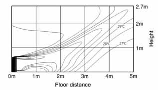
351 7 Temperature and air flow distribution Console AM36FNJDEH/EU (1) Cooling air velocity distribution Discharge angle (Default) : 4º (2) Cooling temperature distribution Discharge angle (Default) : 4º (3) Heating air velocity distribution Discharge angle (Default) : 4º (4) Heating temperature distribution Discharge angle (Default) : 4º 31
352 7 Temperature and air flow distribution Console AM4KNJDEH/EU (1) Cooling air velocity distribution Discharge angle (Default) : 4º (2) Cooling temperature distribution Discharge angle (Default) : 4º (3) Heating air velocity distribution Discharge angle (Default) : 4º (4) Heating temperature distribution Discharge angle (Default) : 4º 32
 : 4º (3) Heating air velocity distribution Discharge angle (Default) : 4º (4) Heating temperature distribution Discharge angle (Default) : 4º")
353 7 Temperature and air flow distribution Console AM6FNJDEH/EU (1) Cooling air velocity distribution Discharge angle (Default) : 4º (2) Cooling temperature distribution Discharge angle (Default) : 4º (3) Heating air velocity distribution Discharge angle (Default) : 4º (4) Heating temperature distribution Discharge angle (Default) : 4º 33
VRF. Technical Data Book. All indoor units for Europe (R410A, 50Hz, HP/HR)
") VRF Technical Data Book All indoor units for Europe (R41A, Hz, HP/HR) History Version Modification Date Remark Ver.1. Release VRF DVM S Indoor Unit TDB for Europe 1.8.31. Ver.1.1 Updated heating operation
VRF Technical Data Book All indoor units for Europe (R41A, Hz, HP/HR) History Version Modification Date Remark Ver.1. Release VRF DVM S Indoor Unit TDB for Europe 1.8.31. Ver.1.1 Updated heating operation
DVM. Technical Data Book
 DVM Technical Data Book Products 1 2 3 Outdoor units Line-up Accessories 2 Outdoor units 1 2 3 4 5 6 Specifications Operation limit Electrical wiring diagram Sound level Cycle diagrams Dimensional drawing
RAC. Technical Data Book. RAC(Quantum) for North America (R410A, 60Hz, HP) Model : AR09/12/18/24KSFPDWQNCV AR09/12/18/24KSFPDWQXCV
 for North America (R410A, 60Hz, HP) Model : AR09/12/18/24KSFPDWQNCV AR09/12/18/24KSFPDWQXCV") RAC Technical Data Book RAC(Quantum) for North America (R410A, 60Hz, HP) Model : AR09/12/18/24KSFPDWQNCV AR09/12/18/24KSFPDWQXCV History Version Modification Date Remark Ver 1.0 Release RAC (Quantum) TDB
RAC Technical Data Book RAC(Quantum) for North America (R410A, 60Hz, HP) Model : AR09/12/18/24KSFPDWQNCV AR09/12/18/24KSFPDWQXCV History Version Modification Date Remark Ver 1.0 Release RAC (Quantum) TDB
RAC. Technical Data Book. RAC(Max Heat) for North America (R410A, 60Hz, HP) Model : AR09/12KSWSPWKNCV AR09/12KSWSPWKXCV
 for North America (R410A, 60Hz, HP) Model : AR09/12KSWSPWKNCV AR09/12KSWSPWKXCV") RAC Technical Data Book RAC(Max Heat) for North America (R410A, 60Hz, HP) Model : AR09/12KSWSPWKNCV AR09/12KSWSPWKXCV History Version Modification Date Remark Ver.1.0 Release RAC (Max Heat) TDB for North
RAC Technical Data Book RAC(Max Heat) for North America (R410A, 60Hz, HP) Model : AR09/12KSWSPWKNCV AR09/12KSWSPWKXCV History Version Modification Date Remark Ver.1.0 Release RAC (Max Heat) TDB for North
Engineering Data High-wall Type (3 series) Indoor Unit. Contents MMK-AP0073H MMK-AP0093H MMK-AP0123H MMK-AP0153H MMK-AP0183H MMK-AP0243H.
 Indoor Unit. Contents MMK-AP0073H MMK-AP0093H MMK-AP0123H MMK-AP0153H MMK-AP0183H MMK-AP0243H.") E09-311 Engineering Data High-wall Type (3 series) Indoor Unit Model name: MMK-AP0073H MMK-AP0093H MMK-AP0123H MMK-AP0153H MMK-AP0183H MMK-AP0243H Contents 1 Specifications 2 Dimensions 3 Center of gravity
E09-311 Engineering Data High-wall Type (3 series) Indoor Unit Model name: MMK-AP0073H MMK-AP0093H MMK-AP0123H MMK-AP0153H MMK-AP0183H MMK-AP0243H Contents 1 Specifications 2 Dimensions 3 Center of gravity
Engineer Reference 1 / / A 35 7/16 X 7 7/8 X 23 5/8 31 1/8 X 21 7/8 X 11 1/4 14 T T 75 R410A oz/ft over 50' 265 / 318 / 388
 Slim Duct, single zone split system SUBMITTAL EH035CAV / UH035CAV Specifications Nominal Capacity Cooling/Heating (Btu/h) 12,000 / 13,600 Cooling (Btu/h) 3,300-14,300 Capacity Range Heating (Btu/h) 3,100-18,000
SINGLE. Technical Data Book. Multi-position AHU for North America (R410A, 60Hz, H/P) Model : AC***KNZDCH/AA (IDU) AC***JXADCH/AA (ODU)
 Model : AC***KNZDCH/AA (IDU) AC***JXADCH/AA (ODU)") SINGLE Technical Data Book Multi-position AHU for North America (R41A, 6Hz, H/P) Model : AC***KNZDCH/AA (IDU) AC***JXADCH/AA (ODU) History Version Modification Date Remark Ver.. Release SINGLE Multi-position
SINGLE Technical Data Book Multi-position AHU for North America (R41A, 6Hz, H/P) Model : AC***KNZDCH/AA (IDU) AC***JXADCH/AA (ODU) History Version Modification Date Remark Ver.. Release SINGLE Multi-position
EHS. EHS Split (50Hz)
") EHS EHS Split (50Hz) I. Products 1. Nomenclature......... 5 2. Line-up.......... 7 II. Outdoor Unit 1. Specification...... 9 2. Capacity Tables..... 12 3. Capacity Correction..... 15 4. Dimensional Drawings.............
EHS EHS Split (50Hz) I. Products 1. Nomenclature......... 5 2. Line-up.......... 7 II. Outdoor Unit 1. Specification...... 9 2. Capacity Tables..... 12 3. Capacity Correction..... 15 4. Dimensional Drawings.............
High Static Duct Type (6 series)
") E6-002 High Static Duct Type (6 series) MMD-AP0726HP-E MMD-AP0966HP-E Contents. Specifications... 2 2. Dimensions.... Center of gravity...5 4. Piping diagram... 6 5. Wiring diagram... 7 6. Electrical characteristics....
E6-002 High Static Duct Type (6 series) MMD-AP0726HP-E MMD-AP0966HP-E Contents. Specifications... 2 2. Dimensions.... Center of gravity...5 4. Piping diagram... 6 5. Wiring diagram... 7 6. Electrical characteristics....
UDZ Swirl diffuser. Product facts. Quick-selection. Swirl diffuser UDZ. Product code example:
 UDZ Swirl diffuser Swirl diffuser UDZ, which is intended for installation in a ventilation duct, can be used in premises with a large volume, for example factory premises, storage areas, superstores, halls,
MVD. Wall Mounted Split DC Service manual. CL23410 to CL23416 English
 MVD Wall Mounted Split DC Service manual www.mundoclima.com CL23410 to CL23416 English Content 1. Features... 2 2. Specifications... 3 3. Dimensions... 5 4. Piping Diagrams... 6 5. Wiring Diagrams... 7
MS15 High-Efficiency Mini-Split System
 MS15 High-Efficiency Mini-Split System Up to 15 SEER Performance Product Features R-410A chlorine-free refrigerant High-efficiency performance: up to 15 SEER DC Inverter technology compressor Auto-restart
EHS. EHS GEN3 MONO (50Hz)
") EHS EHS GEN3 MONO (50Hz) I. Products 1. Nomenclature.... 5 2. Line-up....... 7 1. Specification...... 9 2. Capacity Tables..... 13 3. Dimensional Drawings............. 19 4. Piping Diagrams..... 23 5.
EHS EHS GEN3 MONO (50Hz) I. Products 1. Nomenclature.... 5 2. Line-up....... 7 1. Specification...... 9 2. Capacity Tables..... 13 3. Dimensional Drawings............. 19 4. Piping Diagrams..... 23 5.
4 Way Reversing Valve
 STANDARD 4 Way Reversing Valve SHF series four-way reversing valves are applicable for heat pump systems such as central, unitary and room air conditioners to realize switching between cooling mode and
4 Way Reversing Valve
 STANDARD 4 Way Reversing Valve SHF series four-way reversing valves are applicable for heat pump systems such as central, unitary and room air conditioners to realize switching between cooling mode and
MS20 High-Efficiency Mini-Split System
 MS20 High-Efficiency Mini-Split System Up to 20 SEER Performance Product Features R-410A chlorine-free refrigerant High-efficiency performance up to 20 SEER DC Inverter technology compressor Indoor antibacterial
SINGLE Technical Data Book. SINGLE for Europe (R410A, HP)
") SINGLE Technical Data Book SINGLE for Europe (R4A, HP) History Ver.1. Release Single TDB for Europe 16. 11. 2 Ver.1.1 Add tco2e data (Specifications) 16. 12. 9 Ver.1. 1.. 9 2 CAC - World-class energy efficiency
SINGLE Technical Data Book SINGLE for Europe (R4A, HP) History Ver.1. Release Single TDB for Europe 16. 11. 2 Ver.1.1 Add tco2e data (Specifications) 16. 12. 9 Ver.1. 1.. 9 2 CAC - World-class energy efficiency
Chiller Technical Data Book
 Chiller Technical Data Book DVM Chiller(pump integrated) for Europe (R41A, 5/6Hz, HP) Model : AG42/56/7KSVGNH/EU History Version Modification Date Remark Ver.1. Release DVM Chiller(pump integrated) TDB
S /5000 BTU/Hr. 1000/1500 Watt
 763.576.32 SPEC-168 D763.422.2211 COOLING SEALED ENCLOSURE COOLING AIR CONDITIONERS Sealed Enclosure Cooling Air Conditioners SPECTRACOOL SLIM FIT INDOOR S6 1/17 BTU/Hr. 3/5 Watt S1 34/5 BTU/Hr. 1/15 Watt
Model: MTZ22. Data. Cylinder count: 1 Displacement [m³/h]: 6,63 Cylinder capacity [cm³]: 38,1 RPM [min -1 ]: 2900 Weight [kg]: 21 Oil charge [dm³]: 1
![Model: MTZ22. Data. Cylinder count: 1 Displacement [m³/h]: 6,63 Cylinder capacity [cm³]: 38,1 RPM [min -1 ]: 2900 Weight [kg]: 21 Oil charge [dm³]: 1](/thumbs/90/102819400.jpg "Model: MTZ22. Data. Cylinder count: 1 Displacement [m³/h]: 6,63 Cylinder capacity [cm³]: 38,1 RPM [min -1 ]: 2900 Weight [kg]: 21 Oil charge [dm³]: 1") Technical data Data Cylinder count: 1 Displacement [m³/h]: 6,63 Cylinder capacity [cm³]: 38,1 RPM [min -1 ]: 2900 Weight [kg]: 21 Oil charge [dm³]: 1 Oil type: 160PZ Crankcase heater type: PTC 35 W Maximum
Technical data Data Cylinder count: 1 Displacement [m³/h]: 6,63 Cylinder capacity [cm³]: 38,1 RPM [min -1 ]: 2900 Weight [kg]: 21 Oil charge [dm³]: 1 Oil type: 160PZ Crankcase heater type: PTC 35 W Maximum
Split. Air Conditioning Technical Data RXM-M
 Split Air Conditioning Technical Data RXM-M Outdoor Unit RXM-M TABLE OF CONTENTS RXM-M 1 Features............................................................. 2 2 Specifications.......................................................
SPBW06 & DPBW06 series
 /,, MODEL SELECTION TABLE INPUT ORDER NO. INPUT VOLTAGE (RANGE) NO LOAD INPUT CURRENT FULL LOAD VOLTAGE CURRENT EFFICIENCY (TYP.) CAPACITOR LOAD (MAX.) SPBW06F-03 310mA 3.3V 0 ~ 1500mA 81% 4700μF SPBW06F-05
Air Conditioners Technical Data
 Air Conditioners Technical Data Concealed ceiling unit with inver ter driven fan E E D E N 1 1-2 0 4 FXSQ-P Air Conditioners Technical Data Concealed ceiling unit with inver ter driven fan E E D E N 1
DC-DC Constant Current Step-Down LED driver LDD-300L LDD-350L LDD-500L LDD-600L LDD-700L CURRENT RANGE
 SPECIFICATION ORDER NO. LDD-00L LDD-0L LDD-00L LDD-00L LDD-700L CURRENT RANGE 00mA 0mA 00mA VOLTAGE RANGE Note. ~ VDC for LDD-00~700L/LW ; ~ 8VDC for LDD-00~700LS CURRENT ACCURACY (Typ.) ±% at VDC input
Service Manual. Models: GWH09ABA-K6DNA1B GWH09ABA-K6DNC8B GWH12ABA-K6DNA1B GWH12ABA-K6DNC8B (Refrigerant R32) GREE ELECTRIC APPLIANCES,INC.
 GREE ELECTRIC APPLIANCES,INC.") Change for Life Service Manual Models: GWH09ABA-K6DNA1B GWH09ABA-K6DNC8B GWH12ABA-K6DNA1B GWH12ABA-K6DNC8B (Refrigerant R32) GREE ELECTRIC APPLIANCES,INC.OF ZHUHAI Table of Contents Part Ⅰ : Technical
Change for Life Service Manual Models: GWH09ABA-K6DNA1B GWH09ABA-K6DNC8B GWH12ABA-K6DNA1B GWH12ABA-K6DNC8B (Refrigerant R32) GREE ELECTRIC APPLIANCES,INC.OF ZHUHAI Table of Contents Part Ⅰ : Technical
RSDW08 & RDDW08 series
 /,, MODEL SELECTION TABLE INPUT ORDER NO. INPUT VOLTAGE (RANGE) NO LOAD INPUT CURRENT FULL LOAD VOLTAGE CURRENT EFFICIENCY (Typ.) CAPACITOR LOAD (MAX.) RSDW08F-03 344mA 3.3V 2000mA 80% 2000μF RSDW08F-05
DC-DC Constant Current Step-Down LED driver LDD-300L LDD-350L LDD-500L LDD-600L LDD-700L CURRENT RANGE
 SPECIFICATION ORDER NO. LDD-00L LDD-0L LDD-00L LDD-00L LDD-700L CURRENT RANGE 00mA 0mA 00mA 00mA VOLTAGE RANGE Note. ~ VDC for LDD-00~700L/LW ; ~ 8VDC for LDD-00~700LS CURRENT ACCURACY (Typ.) ±% at VDC
SERVICE MANUAL OUTDOOR UNIT
 SPLIT-TYPE AIR CONDITIONERS Revision E: MUZ-GE25VAD- A1, MUZ-GE35VAD- A1, MUZ-GE42VAD- A1, MUZ-GE50VAD- A1, MUZ-GE60VAD- A1, MUZ-GE71VAD- A1 and MUZ-GE80VAD- A1 have been added. Please void OBH532 REVISED
NMBTC.COM /
 Common Common Vibration Test:... Conforms to JIS C 60068-2-6, Amplitude: 1.5mm, Frequency 10 to 55 Hz, 1 hour in each of the X, Y and Z directions. Shock Test:...Conforms to JIS C 60068-2-27, Acceleration
Air Conditioning. Technical Data EEDEN RXG-L
 Air Conditioning Technical Data EEDEN15-100 RXG-L Outdoor Unit RXG-L TABLE OF CONTENTS RXG-L 1 Features............................................................. 2 2 Specifications.......................................................
38BXCS STANDARD RACK MODEL. DCS Input/Output Relay Card Series MODEL & SUFFIX CODE SELECTION 38BXCS INSTALLATION ORDERING INFORMATION RELATED PRODUCTS
 DCS Input/Output Relay Card Series STANDARD RACK MODEL 38BXCS MODEL & SUFFIX CODE SELECTION 38BXCS MODEL CONNECTOR Y1 :Yokogawa KS2 cable use Y2 :Yokogawa KS9 cable use Y6 :Yokogawa FA-M3/F3XD32-3N use
Siemens AG Rated current 1FK7 Compact synchronous motor Natural cooling. I rated 7.0 (15.4) 11.5 (25.4) (2.9) 3.3 (4.4)
 11.5 (25.4) (2.9) 3.3 (4.4)") Synchronous motors Siemens 2009 FK7 Compact motors Nural cooling Selection and ordering da Red speed Shaft height n red S P red ΔT=00 K rpm kw (P) Red power Stic torque M 0 ΔT=00 K Red torque ) M red ΔT=00
Synchronous motors Siemens 2009 FK7 Compact motors Nural cooling Selection and ordering da Red speed Shaft height n red S P red ΔT=00 K rpm kw (P) Red power Stic torque M 0 ΔT=00 K Red torque ) M red ΔT=00
MATRIX. EBARA PUMPS EUROPE S.p.A. HORIZONTAL MULTISTAGE PUMPS
 CONTENTS Page - SPECIFICATIONS 200 PUMP SPECIFICATION 200 TYPE KEY 201 SELECTION CHART 202 SELECTION CHART 203 PERFORMANCE CURVE 3 ( 2-3-4-5 impellers ) 204 PERFORMANCE CURVE 3 ( 6-7-8-9 impellers ) 205
Alféa Extensa + and Extensa Duo +
 Alféa Extensa + and Extensa Duo + FR Document n 1592-2~ 12/07/2013 EN Heat pumps air/water split 1 service and 2 services Technical manual Intended for professionals Completed by the installation and operating
COPELAND SCROLL AIR COOLED CONDENSING UNITS
 R404A Refrigerant Scroll R507A Refrigerant R134A Refrigerant STANDARD UNIT WITH: Copeland ZB Scroll Compressors for medium temp applications on R404A/R507A/R134A Copeland ZB & ZF Scroll Compressors for
Heat exchanger. Type WT. For the reheating of airflows in rectangular ducting PD WT 1. 03/2017 DE/en
 X X testregistrierung Heat exchanger Type For the reheating of airflows in rectangular ducting Rectangular hot water heat exchanger for the reheating of airflows, suitable for VAV terminal units Type TVR,
Smaller. 6.3 to 100 After 1 minute's application of rated voltage at 20 C, leakage current is. not more than 0.03CV or 4 (µa), whichever is greater.
, whichever is greater.") Low Impedance, For Switching Power Supplies Low impedance and high reliability withstanding 5000 hours load life at +05 C (3000 / 2000 hours for smaller case sizes as specified below). Capacitance ranges
Low Impedance, For Switching Power Supplies Low impedance and high reliability withstanding 5000 hours load life at +05 C (3000 / 2000 hours for smaller case sizes as specified below). Capacitance ranges
NKT NTC Thermistor. Negative Temperature Coefficient Thermistor FEATURES
 FEATURES Large, strong capacity of suppression of inrush current Big material (B value), small residual Small size, Long life, high reliability and fast response APPLICATIONS Switching -supply, switch,
Lowara SPECIFICATIONS
 SH Series Centrifugal pumps entirely made of AISI 36 stainless steel according to EN 733 (ex DIN 24255). Designed to pump hot, cold and moderately aggressive liquids. Available versions: SHE Close-coupled
Metal Oxide Varistors (MOV) Data Sheet
 Data Sheet") Φ SERIES Metal Oxide Varistors (MOV) Data Sheet Features Wide operating voltage (V ma ) range from 8V to 0V Fast responding to transient over-voltage Large absorbing transient energy capability Low clamping
Φ SERIES Metal Oxide Varistors (MOV) Data Sheet Features Wide operating voltage (V ma ) range from 8V to 0V Fast responding to transient over-voltage Large absorbing transient energy capability Low clamping
First Sensor Quad APD Data Sheet Part Description QA TO Order #
 Responsivity (/W) First Sensor Quad PD Data Sheet Features Description pplication Pulsed 16 nm laser detection RoHS 211/65/EU Light source positioning Laser alignment ø mm total active area Segmented in
Finish: Anticorrosive finish in polyester. Number of motor poles 4=1400 r/min. 50 Hz 6=900 r/min. 50 Hz 8=750 r/min. 50 Hz
 HEP HEPT HEP: Wall-mounted axial fans, with IP65 motor HEPT: Long-cased axial fans, with IP65 motor Wall-mounted axial (HEP) and long-cased (HEPT) fans, with fibreglass-reinforced plastic impeller. Fan:
Split. Air Conditioning Technical Data RXF-A
 Split Air Conditioning Technical Data RXF-A TABLE OF CONTENTS RXF-A 1 Features............................................................. 2 2 Specifications.......................................................
60W AC-DC High Reliability Slim Wall-mounted Adaptor. SGA60E series. File Name:SGA60E-SPEC
 AC-DC High Reliability Slim Wall-mounted Adaptor SGA60E series Ⅵ Ⅴ Ⅱ Ⅱ { ψ. ψ File Name:SGA60E-SPEC 2015-09-15 AC-DC High Reliability Slim Wall-mounted Adaptor SGA60E series SPECIFICATION ORDER NO. SGA60E05-P1J
Precision Metal Film Fixed Resistor Axial Leaded
 Features EIA standard colour-coding Non-Flame type available Low noise and voltage coefficient Low temperature coefficient range Wide precision range in small package Too low or too high ohmic value can
Type selection. Type selection for pressure series from 100 dapa to 3150 dapa
 for pressure series from 100 dapa to 3150 dapa Sound tables according to types for pressure series from 100 dapa to 3150 dapa Weight list and noise values for standard motors Performance curves 1 to 7
DLG Series. Lowara SPECIFICATIONS APPLICATIONS ACCESSORIES MATERIALS. General Catalogue
 DLG Series Submersible pumps with open impeller with grinder assembly for pumping sewage, liquids, wastewater in general and industrial sludge, draining of flooded excavations. SPECIFICATIONS Delivery:
Prepolarized Microphones-Free Field
 Prepolarized Microphones-Free Field MP0 / MP3 / MP / MP / MP / MP / MP8 MP0 MP3 MP MP MP MP MP8 Standards (IEC7) I I I.3 ~ 0k 3 ~ 0k 0 ~.k 0 ~.k 0 ~ 70k 0 ~ k 0 ~ k Open-circuit Sensitivity (mv/pa) (±db)
Swirl diffusers, Variable swirl diffusers Swirl diffusers
 , Variable swirl diffusers Swirl diffuser OD-9 Square or round front mask Square or radial deflector arrangement Plastic deflectors Possible volume control damper in spigot Foam sealing on the flange St
LIBERTY 300. 2012 TS-20090222-00-TEC Κωδικός
 LIBERTY 300 Αντλίες Θερμότητας με μπόιλερ για ζεστά νερά χρήσεως compact LIBERTY 300 Περιγραφή Εσωτερική Μονάδα ECS300T5ZAA 230 V LIBERTY 300 TECHNIBEL PAC ACS Χωρητικότητα 300 lt 2.500,00 ECS300SOLT5ZAA
No item Digit Description Series Reference (1) Meritek Series SI Signal Inductor LI: Leaded Inductor PI: Power Inductor
 Meritek Series SI Signal Inductor LI: Leaded Inductor PI: Power Inductor") PART NUMBERING SYSTEM SI F 0805 K 780 F (1) (2) (3) (4) (5) (6) No item Digit Description Series Reference (1) Meritek Series SI Signal Inductor LI: Leaded Inductor PI: Power Inductor (2) Type F Ferrite
PART NUMBERING SYSTEM SI F 0805 K 780 F (1) (2) (3) (4) (5) (6) No item Digit Description Series Reference (1) Meritek Series SI Signal Inductor LI: Leaded Inductor PI: Power Inductor (2) Type F Ferrite
Electrical Specifications at T AMB =25 C DC VOLTS (V) MAXIMUM POWER (dbm) DYNAMIC RANGE IP3 (dbm) (db) Output (1 db Comp.) at 2 f U. Typ.
 MAXIMUM POWER (dbm) DYNAMIC RANGE IP3 (dbm) (db) Output (1 db Comp.) at 2 f U. Typ.") Surface Mount Monolithic Amplifiers High Directivity, 50Ω, 0.5 to 5.9 GHz Features 3V & 5V operation micro-miniature size.1"x.1" no external biasing circuit required internal DC blocking at RF input &
Surface Mount Monolithic Amplifiers High Directivity, 50Ω, 0.5 to 5.9 GHz Features 3V & 5V operation micro-miniature size.1"x.1" no external biasing circuit required internal DC blocking at RF input &
Aluminum Electrolytic Capacitors (Large Can Type)
") Aluminum Electrolytic Capacitors (Large Can Type) Snap-In, 85 C TS-U ECE-S (U) Series: TS-U Features General purpose Wide CV value range (33 ~ 47,000 µf/16 4V) Various case sizes Top vent construction
Aluminum Electrolytic Capacitors (Large Can Type) Snap-In, 85 C TS-U ECE-S (U) Series: TS-U Features General purpose Wide CV value range (33 ~ 47,000 µf/16 4V) Various case sizes Top vent construction
A31. Aluminium heat exchanger A31
 Aluminium heat exchanger A A Before using the heat exchanger, carefully read the document entitled GENERAL OPERATING INSTRUCTIONS FOR HEAT EXCHANGER USE 98SAE7EN - 9-5-8 A V-V Dimensions ± 5 5 L MAX 99
CSR series. Thick Film Chip Resistor Current Sensing Type FEATURE PART NUMBERING SYSTEM ELECTRICAL CHARACTERISTICS
 FEATURE Operating Temperature: -55 ~ +155 C 3 Watts power rating in 1 Watt size, 1225 package High purity alumina substrate for high power dissipation Long side terminations with higher power rating PART
300 2012 TS-20090222-00-TEC
 LIBERTY 300 Αντλίες Θερμότητας με μπόιλερ για ζεστά νερά χρήσεως compact LIBERTY 300 Περιγραφή Εσωτερική Μονάδα ECS300T5ZAA 230 V LIBERTY 300 TECHNIBEL PAC ACS Χωρητικότητα 300 lt 2.500,00 ECS300SOLT5ZAA
with serial RS485/RS232 output RS485
 with serial RS485/RS232 output RS485 2 Applications Měřící a záznamový systém MS v různých provedeních Building management 2 Industry Meteorology Pharmaceuticals and laboratories Technological processes
Applications Water distribution
 1 FH Series Centrifugal electric pumps according to EN 733 (ex DIN 24255). Electric pumps with pump casing in cast iron designed to pump clean, chemically non-aggressive water and liquids. Available versions:
Aluminum Electrolytic Capacitors
 Aluminum Electrolytic Capacitors Snap-In, Mini., 105 C, High Ripple APS TS-NH ECE-S (G) Series: TS-NH Features Long life: 105 C 2,000 hours; high ripple current handling ability Wide CV value range (47
15W DIN Rail Type DC-DC Converter. DDR-15 s e r i e s. File Name:DDR-15-SPEC
 DIN Rail Type DC-DC Converter ± : DIN Rail Type DC-DC Converter SPECIFICATION MODEL OUTPUT INPUT PROTECTION ENVIRONMENT SAFETY & EMC (Note 5) OTHERS NOTE DC VOLTAGE RATED CURRENT CURRENT RANGE RATED POWER
HIS series. Signal Inductor Multilayer Ceramic Type FEATURE PART NUMBERING SYSTEM DIMENSIONS HIS R12 (1) (2) (3) (4)
 (2) (3) (4)") FEATURE High Self Resonant Frequency Superior temperature stability Monolithic structure for high reliability Applications: RF circuit in telecommunication PART NUMBERING SYSTEM HIS 160808 - R12 (1) (2)
FEATURE High Self Resonant Frequency Superior temperature stability Monolithic structure for high reliability Applications: RF circuit in telecommunication PART NUMBERING SYSTEM HIS 160808 - R12 (1) (2)
Data sheet Thick Film Chip Resistor 5% - RS Series 0201/0402/0603/0805/1206
 Data sheet Thick Film Chip Resistor 5% - RS Series 0201/0402/0603/0805/1206 Scope -This specification applies to all sizes of rectangular-type fixed chip resistors with Ruthenium-base as material. Features
Current Sensing Chip Resistor SMDL Series Size: 0201/0402/0603/0805/1206/1010/2010/2512/1225/3720/7520. official distributor of
 Product: Current Sensing Chip Resistor SMDL Series Size: 0201/0402/0603/0805/1206/1010/2010/2512/1225/3720/7520 official distributor of Current Sensing Chip Resistor (SMDL Series) 1. Features -3 Watts
ZLW Series. Single-stage Monoblock Centrifugal Pump ZL PUMP GROUP.,LTD
 ZLW Series Single-stage Monoblock Centrifugal Pump ZL PUMP GROUP.,LTD 1 Application Apply as the transportation of liquids in the fields of air condition, heating, sanitary water, water treatment cooling,
Solar Laptop Charger with 2.5w/12000mah
 WWW..GR ΕΤΑΙΡΙΑ: ΟΙ. ΦΟΡΤΙΣΤΕΣ ΜΑΣ ΓΙΑ ΟΛΑ ΚΑΙ ΟΛΟΥΣ Solar Laptop Charger with 2.5w/12000mah Specification Battery Type: Lithium-ion polymer battery; Battery capacity: 12000mAh/3.7V 3000mAh lithium polymer
15W DIN Rail Type DC-DC Converter. DDR-15 series. File Name:DDR-15-SPEC
 DIN Rail Type DC-DC Converter ± : DIN Rail Type DC-DC Converter SPECIFICATION MODEL OUTPUT INPUT PROTECTION ENVIRONMENT SAFETY & EMC (Note 5) OTHERS DC VOLTAGE RATED CURRENT CURRENT RANGE RATED POWER RIPPLE
MARKET INTRODUCTION System integration
 MARKET INTRODUCTION System integration Air to Water Split System Inverter Driven Nomιnal Capacities : 5-6,5-9 - 11,5 kwth Max LWT= 60 C & Min OAT = -15 C COP>= 4.1 Air to Water Monoblock Inverter Driven
KYOWA PRODUCT CATALOGUE
 KYOWA PRODUCT CATALOGUE We are focusing on the atmospheric future with technology. KYOWA KAKO Co., Ltd. "Eco-MEVIUS" is not only economical but also ecological product development concept proposed by KYOWA
No Item Code Description Series Reference (1) Meritek Series CRA Thick Film Chip Resistor AEC-Q200 Qualified Type
 Meritek Series CRA Thick Film Chip Resistor AEC-Q200 Qualified Type") Qualified FEATURE Excellent Mechanical Strength and Electrical Stability Ideal for Pick and Place Machinery Stable High Frequency Characteristics Miniature, High Board Density Equivalent Specification
Qualified FEATURE Excellent Mechanical Strength and Electrical Stability Ideal for Pick and Place Machinery Stable High Frequency Characteristics Miniature, High Board Density Equivalent Specification
65W PWM Output LED Driver. IDLV-65 series. File Name:IDLV-65-SPEC
 ~ A File Name:IDLV65SPEC 07050 SPECIFICATION MODEL OUTPUT OTHERS NOTE DC VOLTAGE RATED CURRENT RATED POWER DIMMING RANGE VOLTAGE TOLERANCE PWM FREQUENCY (Typ.) SETUP TIME Note. AUXILIARY DC OUTPUT Note.
NPI Unshielded Power Inductors
 FEATURES NON-SHIELDED MAGNETIC CIRCUIT DESIGN SMALL SIZE WITH CURRENT RATINGS TO 16.5 AMPS SURFACE MOUNTABLE CONSTRUCTION TAKES UP LESS PCB REAL ESTATE AND SAVES MORE POWER TAPED AND REELED FOR AUTOMATIC
± 20% ± 5% ± 10% RENCO ELECTRONICS, INC.
 RL15 RL16, RL17, RL18 MINIINDUCTORS CONFORMALLY COATED MARKING The nominal inductance is marked by a color code as listed in the table below. Color Black Brown Red Orange Yellow Green Blue Purple Grey
SPARE PARTS LIST. for. Infrared oil heater. Model. Daystar. Type. PH5 for 120V 60Hz. May, 2017
 SPARE PARTS LIST for Infrared oil heater Model Daystar Type PH5 for 120V 60Hz May, 2017 *PRICES AND SPECIFICATIONS ARE SUBJECT TO CHANGE WITHOUT NOTICE..* 2017 J.S.O'will, Inc.. Shizuoka Seiki Co. Ltd.
Anti-Corrosive Thin Film Precision Chip Resistor (PR Series)
") (PR Series) Features -Long term life stability and demonstrated the Anti Corrosion claims -Special passivated NiCr film for Anti-Acid and Anti-Damp -Tight tolerance down to ±0.1% -Extremely low TCR down
(PR Series) Features -Long term life stability and demonstrated the Anti Corrosion claims -Special passivated NiCr film for Anti-Acid and Anti-Damp -Tight tolerance down to ±0.1% -Extremely low TCR down
Development of Finer Spray Atomization for Fuel Injectors of Gasoline Engines
 Development of Finer Spray Atomization for Fuel Injectors of Gasoline Engines Tetsuharu MATSUO Yukio SAWADA Yukio TOMIITA This report describes the technology of Fuel Injectors a critical part of the Electronic
QUICKTRONIC PROFESSIONAL QTP5
 osram.com QUICKTRONIC PROFESSIONA QTP5 ECG for T5/ 16mm, T8/ 26mm, DUUX fluorescent lamps QTP5 i.e. UMIUX T5 HO ES 01 Product Features: Up to 100.000 hours lifetime 1 amp start with optimized filament
Lowara APPLICATIONS MATERIALS. General Catalogue
 FH Series Centrifugal electric pumps according to EN 733 (ex DIN 24255). Electric pumps with pump casing in cast iron and impeller in AISI 36* stainless steel, designed to pump hot, cold and moderately
Thin Film Chip Inductor
 Scope -Viking s 0201 and 0402 series inductor is a photo lithographically etched single layer ceramic chip. Viking s design provides high, excellent Q, and superior temperature stability. This highly stable
0.635mm Pitch Board to Board Docking Connector. Lead-Free Compliance
 .635mm Pitch Board to Board Docking Connector Lead-Free Compliance MINIDOCK SERIES MINIDOCK SERIES Features Specifications Application.635mm Pitch Connector protected by Diecasted Zinc Alloy Metal Shell
CSK series. Current Sensing Chip Resistor. Features. Applications. Construction FAITHFUL LINK
 CSK series Current Sensing Chip Resistor Features» 3 Watts power rating in 1 Watt size, 1225 Package» Low TCR of ±100 PPM/ C» Resistance values from 1m to 1 ohm» High purity alumina substrate for high
ELWOOD HIGH PERFORMANCE MOTORS H-SERIES MOTOR DATA
 H-SERIES MOTOR DATA MOTOR MODEL H-3007 H-3016 H-4030-P H-4030-M H-4040 H-4050 H-4075 H-6100 H-6200 H-6300 MECHANICAL DATA (1) Rated Torque, Cont (Stall) 0.8 2.3 3.4 3.4 5.0 6.8 10.2 11.3 22.6 36.7 lb-in
SAW FILTER - RF RF SAW FILTER
 FEATURES - Frequencies from 0MHz to 700MHz - Custom specifications available - Industry standard package configurations - Low-loss saw component - Low amplitude ripple - RoHS compliance - Electrostatic
SPECIFICATIONS. PRODUCT NAME: AC COB15W LED module (3120) General Customer MODEL NAME: CUSTOMER P/N: DATE: 2015-09-10
 General Customer MODEL NAME: CUSTOMER P/N: DATE: 2015-09-10") SPECIFICATIONS PRODUCT NAME: AC COB5W LED module (320) CUSTOMER: General Customer MODEL NAME: CUSTOMER P/N: DATE: 205-09-0 APT Electronics Ltd. CUSTOMER Prepared by Checked by Approved by Approved by He
SPECIFICATIONS PRODUCT NAME: AC COB5W LED module (320) CUSTOMER: General Customer MODEL NAME: CUSTOMER P/N: DATE: 205-09-0 APT Electronics Ltd. CUSTOMER Prepared by Checked by Approved by Approved by He
Gearmotor Data. SERIES GM9000: We have the GM9434H187-R1
 SERIES GM9: We have the GM9434H187-R1 Gearmotor Data Item Parameter Symbol Units 5.9:1 11.5:1 19.7:1 38.3:1 65.5:1 127.8:1 218.4:1 425.9:1 728.1:1 1419.8:1 2426.9:1 4732.5:1 1 Max. Load Standard Gears
Vertical multistage centrifugal pumps in AISI 316 stainless steel
 VLRI/X Vertical multistage centrifugal pumps in AISI 316 stainless steel The VLRI/X are vertical multistage, in-line, centrifugal pumps, directly connected to an electric motor. They are not self-priming.
LS series ALUMINUM ELECTROLYTIC CAPACITORS CAT.8100D. Specifications. Drawing. Type numbering system ( Example : 200V 390µF)
") Snap-in Terminal Type, 85 C Standard Withstanding 3000 hours application of rated ripple current at 85 C. Compliant to the RoHS directive (2011/65/EU). LS Smaller LG Specifications Item Category Temperature
Snap-in Terminal Type, 85 C Standard Withstanding 3000 hours application of rated ripple current at 85 C. Compliant to the RoHS directive (2011/65/EU). LS Smaller LG Specifications Item Category Temperature
LR Series Metal Alloy Low-Resistance Resistor
 LR Series Metal Alloy LowResistance Resistor This specification is applicable to lead free, halogen free of RoHS directive for metal alloy lowresistance resistor. The product is for general purpose. The
C4C-C4H-C4G-C4M MKP Series AXIAL CAPACITORS PCB APPLICATIONS
 C4C-C4H-C4G-C4M AXIAL CAPACITORS PCB APPLICATIONS General characteristics - Self-Healing - Low losses - High ripple current - High contact reliability - Suitable for high frequency applications 40 ±5 L
Creative TEchnology Provider
 1 Oil pplication Capacitors are intended for the improvement of Power Factor in low voltage power networks. Used advanced technology consists of metallized PP film with extremely low loss factor and dielectric
LR Series Metal Alloy Low-Resistance Resistor
 Tel : 881745 Fax : 881749 LR Series Metal Alloy LowResistance Resistor This specification is applicable to lead free, halogen free of RoHS directive for metal alloy lowresistance resistor. The product
TM ZX. Copeland EazyCool TM. ZX Digital. Μηχανήµατα Εξωτερικής Χρήσης
 TM ZX Copeland EazyCool TM ZX Digital Μηχανήµατα Εξωτερικής Χρήσης Copeland EazyCool TM ZX Αγορές Στόχοι Καταστήµατα Τροφίµων και πώλησης φαγητού, όπως Mini Markets Αλυσίδες Εστίασης / Γρήγορου Φαγητού
NTC Thermistor:SCK Series
 Features. RoHS compliant 2. Body size Ф5mm~ Ф 30mm 3. Radial lead resin coated 4. High power rating 5. Wide resistance range 6. Cost effective 7. Operating temperature range: Φ5mm:-40~+50 Φ8~Φmm:-40~+70
Metal thin film chip resistor networks
 Metal thin film chip resistor networks AEC-Q200 Compliant Features Relative resistance and relative TCR definable among multiple resistors within package. Relative resistance : ±%, relative TCR: ±1ppm/
CS400 SQUARE DIFFUSER WITH ADJUSTABLE AIR PATTERN TECHNICAL DETAILS. APPLICATION Product CS400. CONSTRUCTION Core, shape Square plate
 CS00 AIR OULE SYSEMS RESIDENIAL WAY HROW ADJUSABLE SQUARE DIFFUSER WIH ADJUSABLE AIR PAERN Square aluminium ceiling diffuser with way air pattern and adjustable core. For supply and exhaust applications.
OWA-60E series IP67. 60W Single Output Moistureproof Adaptor. moistureproof. File Name:OWA-60E-SPEC
 Single Output Moistureproof Adaptor OWA-60E series IP67 Ⅱ Ⅱ moistureproof I File Name:OWA-60E-SPEC 0-04- Single Output Moistureproof Adaptor OWA-60E series SPECIFICATION MODEL OWA-60E- OWA-60E- OWA-60E-0
DAIKIN ALTHERMA MONOBLOC έκδοση 006-008 kw
 START Εισαγωγή συστήµατος Monobloc ισχύος 006-008kW Εύκολη εγκατάσταση NEW Συµπαγής σχεδιασµός Εµπεριέχει όλα τα παρελκόµενα Φιλικό προς το περιβάλλον σε διαδικασία απόκτησης του σήµατος Το σύστηµα: εξωτερική
Daewoo Technopark A-403, Dodang-dong, Wonmi-gu, Bucheon-city, Gyeonggido, Korea LM-80 Test Report
 LM-80 Test Report Approved Method: Measuring Lumen Maintenance of LED Light Sources Project Number: KILT1212-U00216 Date: September 17 th, 2013 Requested by: Dongbu LED Co., Ltd 90-1, Bongmyeong-Ri, Namsa-Myeon,
Current Sensing Chip Resistor
 Features -3 atts power rating in 1 att size, 1225 package -Low CR of ±100 PPM/ C -Resistance values from 1m to 1 ohm -High purity alumina substrate for high power dissipation -Long side terminations with
65W PWM Output LED Driver. IDPV-65 series. File Name:IDPV-65-SPEC
 IDPV65 series ~ A File Name:IDPV65SPEC 07060 IDPV65 series SPECIFICATION MODEL OUTPUT OTHERS NOTE DC VOLTAGE RATED CURRENT RATED POWER DIMMING RANGE VOLTAGE TOLERANCE PWM FREQUENCY (Typ.) SETUP TIME Note.
Multilayer Chip Inductor
 Features -Monolithic structure for high reliability -High self-resonant frequency -Excellent solderability and high heat resistance Construction Applications -RF circuit in telecommunication and other