Amphenol GB- Series Plugs Miniature Bayonet Lock Connectors Complies with MIL-C CE-2Pa
|
|
|
- Μαγδαληνή Λόντος
- 9 χρόνια πριν
- Προβολές:
Transcript
1 62 G- Series Plugs Miniature ayonet Lock onnectors omplies with MIL E-2Pa This miniature bayonet lock connector series offers designers important features not found in any other range of connectors. They are developed and manufactured entirely in the U.K. by MPHENOL Ltd., and have full qualification approval to ritish Standards Specification S 95 F0017 and ritish Defence Specification DEF STN (Part 3) Sec. 7. This catalogue to be used in conjunction with atalogues: E-2Ra 62G Series Receptacles E-2a 62G Series ccessories mphenol 1

2 62G and Pattern 6 New Planforms urrent: urrent: (a) Maximum current per individual contact (in isolation)* at ambient temperature of 85 ontact size : 23 (a) Maximum current per individual contact (in isolation)* at ambient temperature of 85 (b) Maximum current per contact through all contacts simultaneously at an ambient temperature of 85 ontact size : (b) ontact size 8: 45 Maximum current per contact through all contacts simultaneously at an ambient temperature of 85 ontact size 8: 40 Sea level 8500m (27,900ft) 21,340m (70,OOOft) 13 mbar 3 mbar 44 mbar Voltage rating I II III I II III I II III Working voltages ** (nominal) d.c. or a.c. peak Voltage proof d.c. or a.c. peak * i.e. when only one contact per connector is electrically loaded. 1 mbar= 2 N/m 2 =0 Pa ** Establishment of electrical safety factors is the responsibility of the user 2
 d.c. or a.c. peak Voltage proof 20 3000 3000 10 1300 1300 660 760 750 d.c. or a.c. peak * i.e. when only one contact per connector is electrically loaded.")
3 ONTENTS Page mphenol 62G Solder onnectors 4 Schedule of Tests 5-6 onnector Styles vailable 7 Insert vailability 8 Ordering 62G Series onnectors -11 Plugs - Table of Styles -13 Plugs -19 Insert Orientations Key/Keyway Orientations 21

4 This catalogue to be used in conjunction with atalogues: E-2Ra 62G Series Receptacles E-2a 62G Series ccessories This miniature bayonet lock connector series offers designers important features not found in any other range of connectors. The range has full qualification approval to ritish Standards Specification S 95 FOO 17 and ritish Defence Specification DEF STN (Part 3) Sec G Series connectors - developed and manufactured entirely in the United Kingdom by mphenol Limited. They are the first and only ritish connectors to have achieved this. doubly strong position which mphenol are well geared to handle. The manufacturing facilities of the Whitstable plant have been cited as exemplary in Europe. ertainly the layout is extensive and extremely efficient; safety awards have been attained every time returns have been submitted to the ritish Safety ouncil. 62G Series connectors have been well established with Government authorities on an international scale and users can be found in Sweden, Denmark, Norway, Finland, Germany, Spain, Holland, India, anada and Italy. Derating onnectors must be derated under the following operating conditions: 1. t elevated ambient temperatures, the current ratings are reduced so that total imum hot spot temperature of 5 is not exceeded. 2. t high altitudes, revised voltage ratings become effective as shown on page When connectors to different specifications are intermated (e.g. S 95 FOO 17 and MIL-26482), the combination must not be operated under conditions more severe than the less stringent clause of either specification. mphenol 62G connectors are designed to meet the most stringent requirements of both specifications. Military Specifications ritish Standards Specification S 95 FOO 17 closely corresponds to the United States Military Specification MIL solder terminations. ertain differences exist between the schedules which can be seen on pages 2 and 3. pproved gauges are used to check interchangeability of 62G series with other connectors manufactured to S 95 FOO 17 or MIL mphenol 62G solder connectors asic onstruction onnector shells are machined from solid aluminium bar stock - not forged or extruded as in competitive designs. Machining has inherent advantages in terms of strength and adaptability. 62G Series can be supplied in brass or stainless steel, for instance. The normal shell finish used, which has a high resistance to corrosion, is zinc cobalt olive drab. Other finishes may be supplied to special order, such as cadmium plate which is available by adding deviation (7) to the end of part number. Inserts are of polychloroprene rubber compounded to an mphenol specification. Operating temperature range is -55 to 5, and the connectors have gold-plated contacts designed for soldered connections. onfigurations for size contacts range between 2 contacts in the size 8.7mm (0.5in diameter) shell up to a imum of 61 contacts in the size 36.1 mm (1.5in diameter) shell. Intermediate sizes, and contact data for heavier current ratings are shown in the insert availability chart on page 6 and 7. Hermetic connectors with glass sealed dialectric are manufactured with mild steel shells and nickel iron contacts plated tin over copper. * Other finishes are available on request. Protection gainst Mis-Mating or ross-plugging In S 95 FOO 17 positive shell-to-shell keying is provided with keys and keyways in a choice of either the normal (N) or any of the four preferred alternate positions:,, E and F. This prevents mismating between shells of different orientations and overcomes the difficulties associated with rotated inserts and a standard key-keyway orientation. In the latter system, damage to the inserts or contacts can result if excessive force is used to engage non-mating pairs. Rotated inserts are, however, permissible in S 95 FOO 17 connectors if required to mate with or replace units to MIL mounted in existing equipment. onnectors have normal orientations manufactured to S 95 FOO 17 or MIL are fully intermateable as also are connectors with inserts in positions W, X, Y or Z. 4

5 Schedule of Tests Required for Qualification pproval Tests rief Description Visual Examination Dimensions, outline mass(including contacts) ompatability Gauging procedure Polarization Engaging and separating force, connector ontact Holding Force Sealing (air pressure) Sealing Hermetic ontact Resistance Housing () ontinuity Insulation Resistance Voltage Proof Soldering umping Vibration Shock cceleration (Steady State) Rapid hange of Temperature limatic Sequence Flammability Damp Heat (Steady State) Engagement : 0,90 Nm (8.0 lbf.in.) to 4,97 Nm (44 lbf.in.) according to shell size. Separation min: 0, Nm (2.0 lbf.in.) to 1,58 Nm (.0 lbf.in.) according to shell size. 0,21 N (0.047 lbf) min.size 0,56 N (0.6 lbf)min. size Max leakage 28,53 unm/s (1 cm3/h), 1 bar (.5 p.s.i.) differential. Hermetic receptacles have a leak of 0.1 micron cubic foot per hour (1 x -6m3/s) 5 milliohms. 0 milliohms. 5 milliohms. grounding spring styles. 5,000 Megaohms at V d.c. See page 7. Duration 1 minute s S 95: 1974, lause , Method 2. s S 95: 1974, lause ,000 - bumps / 390m / s2 (40 gn). s S 95: 1974, lause Procedure. Hz to 5000 Hz, 0.75 mm / gn. s S 95: 1974, lause m/s2 (0 g n). s S 95: 1974, lause m/s2 (50 gn). s S 95: 1974, lause to s S 95: 1974, lause Severity 55/5/56. s S 95: 1974, lause Direct flame applied, duration 1 minute. s S 95: 1974, lause Severity 56 days. 5
 to 1,58 Nm (.0 lbf.in.) according to shell size. 0,21 N (0.047 lbf) min.size 0,56 N (0.6 lbf)min. size Max leakage 28,53 unm/s (1 cm3/h), 1 bar (.5 p.s.i.) differential.")
6 Schedule of Tests Required for Qualification pproval Tests rief Description Immersion (at low air pressure) Mechanical Endurance High Temperature Endurance Mould Growth Salt Mist Dust Robustness of Terminations ontact Retention (in insert) Insert Retention (in shell) Test Prod Damage Impact Grounding Spring Holding Force Plugs with grounding springs only. Fluid Resistance ompass Safe Distance 3 cycles at 30 mins each cycle, total immersion in water at pressure 44 m bar. 500 operations minimum Long term: 1,000 hrs. at 850 ambient carrying the specified current. Short term: 250 hrs at 50, no current. s S 95: 1974, lause days duration. s S 95: 1974, lause Severity 1. s S 95: 1974, lause Exposure 30 minutes. 44,5 N (1bf) size,2 N (5 lbf) size 67,0 N (15 lbf) min. size 1,0 N (25 lbf) min. size 517 KN1m2 (751bf/in2) min. Moment: 0,056 Nm (0.5 lbf in) size 0,5 Nm (2 lbf in) size Five impacts, drop height 1 m (3ft.3 in.). 1,17 N (0.263 lbf) to 2,74 N (0.6 lbf) according to size. Immersion in 4 solvents and 9 fluids including aircraft fuels, lubricating oils and hydraulic fluids. s S 95: 1974, lause mm (5.0 in) min. 6

7 onnector Styles vailable Plugs Straight Plug See Pages -17 ccessories See atalogue E-2a Grounded Plug See Page udio Plug See Page Push on - Pull off See Page 19 7

8 Insert vailability NOTES * This insert arrangement is not included in.s. spec., but is available and. listed in MIL Due to the arrangement of contacts in the - insert arrangement it is classified, for current derating, in the shell size range -. Lettering of inserts shown above corresponds to view of front (mating surface of pin inserts or rear face (cable accessory end) of socket inserts. KEY No size contacts O No size contacts URRENT RTING Maximum current per individual contact (in isolation) at a imum ambient temperature of 85 : contact 7.5 contact 13-O The performance of 62G Series connectors at all times exceeds the imum continuous bunched rating of the appropriate size wire, or cable of equivalent temperature rating. This bunched rating is therefore the determining factor. In the case of mixed loadings, the greatest individual load shall be the bunched loading. In any combination of ambient temperature plus temperature rise due to current flow through the contacts, the imum connector internal hot spot temperature of 5 must not be exceeded. That is, when only one contact per connector is loaded. 8
 at a imum ambient temperature of 85 : contact 7.")
9 Insert vailability VOLTGE RTINGS LTITUDE D.. WORKING VOLTGE.. WORKING VOLTGE R.M.S. PROOF VOLTGE D.. OR.. PEK Rating 1 Sea level mb at 8,500m (27,800 ft) mb at,000m (66,000 ft) Rating 2 Sea level 300 mb at 8,500m (27,800 ft) 44 mb at ",000m (66,000 ft) VOLTGE RTINGS Two categories of voltage rating are specified in S95 F0017, F0038 and N0001. Rating 1 (700V d.c. working at sea-level) pplicable to the high contact density inserts shown in the upper section of the insert availability diagram above. Rating 2 (00V d.c. working at sea-level) pplicable to the inserts shown in the lower section of the insert availability diagram. LTITUDE-THOUSNDS OF FEET (METRES) Relationship between flashover voltage and altitude for each voltage rating ltitude derating. Information on voltage derating for operation at altitudes above sea-level can be obtained from the flashover voltage altitude curves on the left. 9
 pplicable to the inserts shown in the lower section of the insert availability diagram.")
10 Ordering 62G Series onnectors To obtain the specific connector required write down the connector number from the typical example below. Only inserts shown in the availability chart on p. &11 can be specified. ll connectors are delivered with protective dust covers 62G SHELL STYLE 1 4 E Series designation 62 G - luminium shell 62 G SS -Stainless steel shell* 62 G U - rass shell* *consult factory for availability 62G-XXH-Hermetic mild steel shell. Specification key 1 - Styles originally specified in MIL Styles exclusive to S95 F0017 style 0 - Receptacle wall mounting 1 - Receptacle cable mounting 2 - Receptacle box mounting 3 - Receptacle, solder flange mounting 4 - Receptacle, internally threaded with cable accessories as illustrated, for single hole mounting 6 - Plug cable mounting 7- Receptacle, plain shell, single hole mounting Environmental code - Plain shell, exposed solder buckets. No grommet E - Insert seal and grommet seal with grommet nut (excluding E which has plain shell and no grommet or nut) F - s (E) but grommet nut has integral strain relief clamp H - Hermetic seal no cable accessories J - s (E) but with resilient gland seal and nut for unscreened jacketed cable. No grommet supplied. See pp for accessory to accept screened jacketed cable. P - Potting construction complete with potting mould T - Exposed solder buckets. Threaded shell for cable accessories HOW TO ORDER FROM MS ONNETOR NUMERS onnector numbers in the MPHENOL and MS numbering systems. Only alternative insert orientations are specified in MIL which does not include alternative key/keyway orientations. MS31 - E -11 P X 62G - E -11 P X

11 Ordering 62G Series onnectors INSERT RRNGEMENT 11 P (044) size (in sixteenths of an inch) 8,,,,,,, Number of contacts 2, 3, 4, 5, 6, 7, 8,, 11,,, 19, 21', 23, 26, 32, 41, 55, 61 * consult factory for availability ontact Style P - Pins S - Sockets For hermetic connectors. P3 denotes pin contacts with solder bucket terminations. (Standard range). P2 denotes pin contacts with flattened and pierced terminations. (Special order). Orientation (Omit if normal orientation) Keys/Keyways: ',,, D', E. F, (see p. 31) Inserts: W,X,Y,Z.(see p56/57) *Inactive for new designs Deviations (044) Rough grip heavy duty coupling ring. (046) ox mounting plug. (2)Fitted with extension back shell and strain relief clamp without grommet on F types only (2) Lever coupling ring (219)ontacts for flexible punted wrung (57 and E only) (639) right cadmium plated shells (345) ontacts for flexible punted wiring H,13H 17H only (276) Hermetics with gold plated contacts. (6) lack anodise. (4) Electroless nickel (7) admium plate olive drab HOW TO ORDER FROM.S. ONNETOR NUMERS Select the connector style by reference to S95 F0017 using the code below for identification. Note that the.s. Specification includes only certain connectors from the table of styles as shown on pp. 8 & 9. lternative key/keyway orientations are preferred in the S95 F0017 Specification to prevent mis-mating. However, rotated inserts are permissible where connectors are required to mate with or replace items to MIL on existing equipment. 62G - E P M O Style Insert rrangement, see above M - Pin contacts F - Socket contacts lternative Key/Key way Orientation Variant. 0 Standard connector 11
 *Inactive for new designs Deviations (044) Rough grip heavy duty coupling ring. (046) ox mounting plug.")
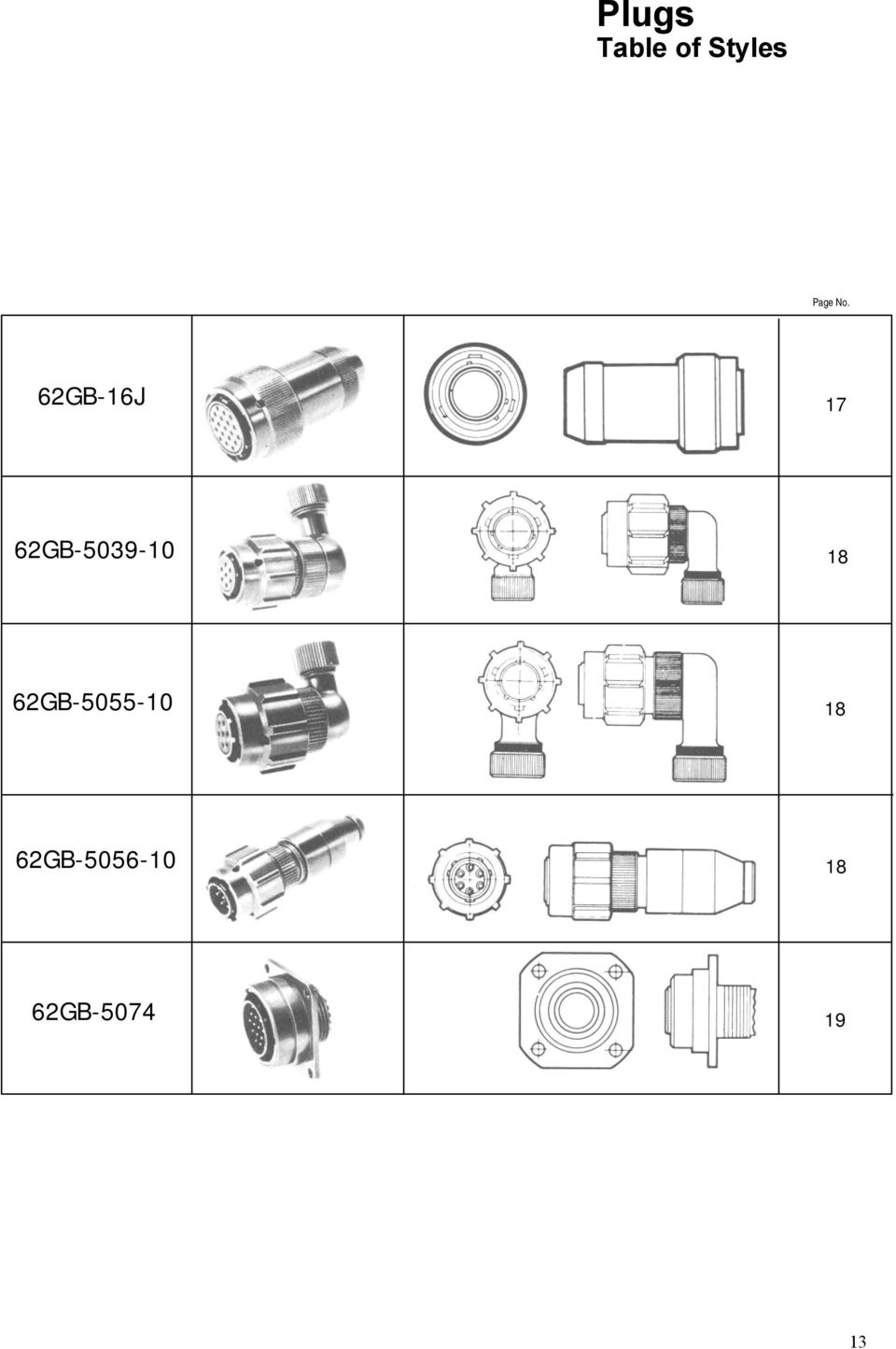
12 Plugs Table of Styles Page No. 62G-56T 62G-56TG 62G G-56T (046) 15 62G-E 62G-F 62G-P 17
 15")
13 Plugs Table of Styles Page No. 62G-J 17 62G G G G
14 Plugs 56T 62G-56T S95 F asic plug with threaded shell to accept standard cable accessories Max & X Thread 7/ - 28 UNEF 9/ - NEF 11/ -NEF 13/ - UNEF 15/ - UNEF 1.1 / - NEF 1.3/ - NEF 1.5/ - NEF 1.7/ - NEF 56TG 62G-56TG S95 F asic plug with threaded shell to accept standard cable accessories. Has shell grounding spring fingers , X Thread 7/ - 28 UNEF 9/ - NEF 11/ NEF 13/ UNEF 15/ - UNEF 1.1 / - NEF 1.3/ - NEF 1.5/ - NEF 11/ - NEF

15 Plugs 62G-1 6 Plug with general duty back shell. No grommet provided. G O.859 0, , M Thread 1/2-28 UNEF 5/8 - NEF 3/4 - UNEF 7/8 - UNEF 1 - UNEF 1.3/ - NEF 1.3/ - NEF 1.7/ - NEF NEF 56T 62G-56T(046) ox-mounting plug. vailable for shell size : other sizes to special order. able accessories cannot be fitted. J K , L 6.32 N 6.32 N 6.32 N 15

16 Plugs E 62G-E MIL MS31E Plug with grommet and grommet nut G I F 62G-F MIL MS31F Plug with grommet and grommet nut fitted with integral strain relief clamp. dia G dia H

17 Plugs P 62G-P MIL MS31P For potted seal. Supplied complete with detachable potting mould and location ring. G Z min J 62G - J Plug with cable clamp for unscreened jacketed cable. No grommet supplied. G Z min

18 Plugs G SD/ X SD/ X Low profile, solder termination plug with 90 screened cable outlet. D G SD/ X Low profile solder termination plug with size 90 screened cable outlet. D G udio plug with solder termination / /

19 Plugs G-5074 Flange mounting push/pull plug with threaded shell to accept standard cable accessories. L / - NEF / - NEF / - NEF

20 Insert Orientations For M I L and for replacement purposes in S95 FOO 17 Normal position with pin contacts lternative position of insert with socket contacts ( counterclockwise) Each diagram shows mating face of insert. lternate position of insert with pin contacts ( clockwise) Insert rrangement Orientation (degrees) Normal W X Y Z

21 Key/Keyway Orientations For S95 F0017 Datum is always taken from major key or keyway. In receptacles the major keyway always remains fixed in relation to the mounting flange. For the ',,,D',E and F orientations, the three bayonet locations and associated minor keyways are rotated complete, in accordance with the table below. N..- The accompanying diagram shows a receptacle shell, with keyways. orresponding key orientations for a mating plug shell are therefore always clockwise. Values for (degrees) Values for θ (degrees) Values for β (degrees) N * D* E F N * D* E F N * D* E F ' S Values for ϕ (degrees) Orientation Values for ω (degrees) Orientation N * D* E F N * D* E F * now inactive for new designs but available for replacement purposes. Superseded in S95 F0017 by orientations E and F. 21
22
23 62 G- Series Receptacles Miniature ayonet Lock onnectors omplies with MIL E-2Ra This miniature bayonet lock connector series offers designers important features not found in any other range of connectors. They are developed and manufactured entirely in the U.K. by MPHENOL Ltd., and have full qualification approval to ritish Standards Specification S 95 F0017 and ritish Defence Specification DEF STN (Part 3) Sec. 7. This catalogue to be used in conjunction with atalogues: E-2Pa 62G Series Plugs E-2a 62G Series ccessories mphenol 1
24 62G and Pattern 6 New Planforms urrent: urrent: (a) Maximum current per individual contact (in isolation)* at ambient temperature of 85 ontact size : 23 (a) Maximum current per individual contact (in isolation)* at ambient temperature of 85 (b) Maximum current per contact through all contacts simultaneously at an ambient temperature of 85 ontact size : (b) ontact size 8: 45 Maximum current per contact through all contacts simultaneously at an ambient temperature of 85 ontact size 8: 40 Sea level 8500m (27,900ft) 21,340m (70,OOOft) 13 mbar 3 mbar 44 mbar Voltage rating I II III I II III I II III Working voltages ** (nominal) d.c. or a.c. peak Voltage proof d.c. or a.c. peak * i.e. when only one contact per connector is electrically loaded. 1 mbar= 2 N/m 2 =0 Pa ** Establishment of electrical safety factors is the responsibility of the user 2
25 ONTENTS Page mphenol 62G Solder onnectors 4 Schedule of Tests 5-6 onnector Styles vailable 7 Insert vailability 9- Ordering 62G Series onnectors 11- ox Mounting Receptacles - Table of Styles 13- ox Mounting Receptacles Single Hole Fixing Receptacles - Table of Styles - Single Hole Fixing Receptacles able Mounting Receptacles - Table of Styles 31 able Mounting Receptacles Insert Orientations 35 Key/Keyway Orientations 36
26 This catalogue to be used in conjunction with atalogues: E-2Pa 62G Series Receptacles E-2a 62G Series ccessories mphenol 62G solder connectors This miniature bayonet lock connector series offers designers important features not found in any other range of connectors. The range has full qualification approval to ritish Standards Specification S 95 FOO 17 and ritish Defence Specification DEF STN (Part 3) Sec G Series connectors - developed and manufactured entirely in the United Kingdom by mphenol Limited. They are the first and only ritish connectors to have achieved this. doubly strong position which mphenol are well geared to handle. The manufacturing facilities of the Whitstable plant have been cited as exemplary in Europe. ertainly the layout is extensive and extremely efficient; safety awards have been attained every time returns have been submitted to the ritish Safety ouncil. 62G Series connectors have been well established with Government authorities on an international scale and users can be found in Sweden, Denmark, Norway, Finland, Germany, Spain, Holland, India, anada and Italy. Derating onnectors must be derated under the following operating conditions: 1. t elevated ambient temperatures, the current ratings are reduced so that total imum hot spot temperature of 5 is not exceeded. 2. t high altitudes, revised voltage ratings become effective as shown on page When connectors to different specifications are intermated (e.g. S 95 FOO 17 and MIL-26482), the combination must not be operated under conditions more severe than the less stringent clause of either specification. mphenol 62G connectors are designed to meet the most stringent requirements of both specifications. Military Specifications ritish Standards Specification S 95 FOO 17 closely corresponds to the United States Military Specification MIL solder terminations. ertain differences exist between the schedules which can be seen on pages 2 and 3. asic onstruction 62G Series can be supplied in brass or stainless steel. The normal shell finish used, which has a high resistance to corrosion, is zinc cobalt olive drab. Other finishes may be supplied to special order, such as cadmium plate which is available by adding deviation (7) to the end of part number. Inserts are of polychloroprene rubber compounded to an mphenol specification. Operating temperature range is -55 to 5, and the connectors have gold-plated contacts designed for soldered connections. onfigurations for size contacts range between 2 contacts in the size 8.7mm (0.5in diameter) shell up to a imum of 61 contacts in the size 36.1 mm (1.5in diameter) shell. Intermediate sizes, and contact data for heavier current ratings are shown in the insert availability chart on page 6 and 7. Hermetic connectors with glass sealed dialectric are manufactured with mild steel shells and nickel iron contacts plated tin over copper. * Other finishes are available on request. Protection gainst Mis-Mating or ross-plugging In S 95 FOO 17 positive shell-to-shell keying is provided with keys and keyways in a choice of either the normal (N) or any of the four preferred alternate positions:,, E and F. This prevents mismating between shells of different orientations and overcomes the difficulties associated with rotated inserts and a standard key-keyway orientation. In the latter system, damage to the inserts or contacts can result if excessive force is used to engage non-mating pairs. Rotated inserts are, however, permissible in S 95 FOO 17 connectors if required to mate with or replace units to MIL mounted in existing equipment. onnectors have normal orientations manufactured to S 95 FOO 17 or MIL are fully intermateable as also are connectors with inserts in positions W, X, Y or Z. pproved gauges are used to check interchangeability of 62G series with other connectors manufactured to S 95 FOO 17 or MIL
27 Schedule of Tests Required for Qualification pproval Tests rief Description Visual Examination Dimensions, outline mass(including contacts) ompatability Gauging procedure Polarization Engaging and separating force, connector ontact Holding Force Sealing (air pressure) Sealing Hermetic ontact Resistance Housing () ontinuity Insulation Resistance Voltage Proof Soldering umping Vibration Shock cceleration (Steady State) Rapid hange of Temperature limatic Sequence Flammability Damp Heat (Steady State) Engagement : 0,90 Nm (8.0 lbf.in.) to 4,97 Nm (44 lbf.in.) according to shell size. Separation min: 0, Nm (2.0 lbf.in.) to 1,58 Nm (.0 lbf.in.) according to shell size. 0,21 N (0.047 lbf) min.size 0,56 N (0.6 lbf)min. size Max leakage 28,53 unm/s (1 cm3/h), 1 bar (.5 p.s.i.) differential. Hermetic receptacles have a leak of 0.1 micron cubic foot per hour (1 x -6m3/s) 5 milliohms. 0 milliohms. 5 milliohms. grounding spring styles. 5,000 Megaohms at V d.c. See page 7. Duration 1 minute s S 95: 1974, lause , Method 2. s S 95: 1974, lause ,000 - bumps / 390m / s2 (40 gn). s S 95: 1974, lause Procedure. Hz to 5000 Hz, 0.75 mm / gn. s S 95: 1974, lause m/s2 (0 g n). s S 95: 1974, lause m/s2 (50 gn). s S 95: 1974, lause to s S 95: 1974, lause Severity 55/5/56. s S 95: 1974, lause Direct flame applied, duration 1 minute. s S 95: 1974, lause Severity 56 days. 5
28 Schedule of Tests Required for Qualification pproval Tests rief Description Immersion (at low air pressure) Mechanical Endurance High Temperature Endurance Mould Growth Salt Mist Dust Robustness of Terminations ontact Retention (in insert) Insert Retention (in shell) Test Prod Damage Impact Grounding Spring Holding Force Plugs with grounding springs only. Fluid Resistance ompass Safe Distance 3 cycles at 30 mins each cycle, total immersion in water at pressure 44 m bar. 500 operations minimum Long term: 1,000 hrs. at 85 0 ambient carrying the specified current. Short term: 250 hrs at 5 0, no current. s S 95: 1983, lause days duration. s S 95: 1983, lause Severity 1. s S 95: 1983, lause Exposure 30 minutes. 44,5 N (1bf) size,2 N (5 lbf) size 67,0 N (15 lbf) min. size 1,0 N (25 lbf) min. size 517 KN1m2 (751bf/in2) min. Moment: 0,056 Nm (0.5 lbf in) size 0,5 Nm (2 lbf in) size Five impacts, drop height 1 m (3ft.3 in.). 1,17 N (0.263 lbf) to 2,74 N (0.6 lbf) according to size. Immersion in 4 solvents and 9 fluids including aircraft fuels, lubricating oils and hydraulic fluids. s S 95: 1974, lause mm (5.0 in) min. 6
29 onnector Styles vailable Receptacles ox Mounting See Pages ccessories See atalogue E-2a Single Hole Mounting See Pages -30 able Mounting See Pages Hermetic Seal See Pages 19 & 26 7
30 8
31 Insert vailability NOTES * This insert arrangement is not included in.s. spec., but is available and. listed in MIL Due to the arrangement of contacts in the - insert arrangement it is classified, for current derating, in the shell size range -. Lettering of inserts shown above corresponds to view of front (mating surface of pin inserts or rear face (cable accessory end) of socket inserts. KEY No size contacts O No size contacts URRENT RTING Maximum current per individual contact (in isolation) at a imum ambient temperature of 85 : contact 7.5 contact 13-O The performance of 62G Series connectors at all times exceeds the imum continuous bunched rating of the appropriate size wire, or cable of equivalent temperature rating. This bunched rating is therefore the determining factor. In the case of mixed loadings, the greatest individual load shall be the bunched loading. In any combination of ambient temperature plus temperature rise due to current flow through the contacts, the imum connector internal hot spot temperature of 5 must not be exceeded. That is, when only one contact per connector is loaded. 9
32 Insert vailability VOLTGE RTINGS LTITUDE D.. WORKING VOLTGE.. WORKING VOLTGE R.M.S. PROOF VOLTGE D.. OR.. PEK Rating 1 Sea level mb at 8,500m (27,800 ft) mb at,000m (66,000 ft) Rating 2 Sea level 300 mb at 8,500m (27,800 ft) 44 mb at ",000m (66,000 ft) LTITUDE-THOUSNDS OF FEET (METRES) Relationship between flashover voltage and altitude for each voltage rating VOLTGE RTINGS Two categories of voltage rating are specified in S95 F0017, F0038 and N0001. Rating 1 (700V d.c. working at sea-level) pplicable to the high contact density inserts shown in the upper section of the insert availability diagram above. Rating 2 (00V d.c. working at sea-level) pplicable to the inserts shown in the lower section of the insert availability diagram. ltitude derating. Information on voltage derating for operation at altitudes above sea-level can be obtained from the flashover voltage altitude curves on the left.
33 Ordering 62G Series onnectors To obtain the specific connector required write down the connector number from the typical example below. Only inserts shown in the availability chart on p. &11 can be specified. ll connectors are delivered with protective dust covers 62G SHELL STYLE 1 4 E Series designation 62 G - luminium shell 62 G SS -Stainless steel shell* 62 G U - rass shell* *consult factory for availability 62G-XXH-Hermetic mild steel shell. Specification key 1 - Styles originally specified in MIL Styles exclusive to S95 F0017 style 0 - Receptacle wall mounting 1 - Receptacle cable mounting 2 - Receptacle box mounting 3 - Receptacle, solder flange mounting 4 - Receptacle, internally threaded with cable accessories as illustrated, for single hole mounting 6 - Plug cable mounting 7- Receptacle, plain shell, single hole mounting Environmental code - Plain shell, exposed solder buckets. No grommet E - Insert seal and grommet seal with grommet nut (excluding E which has plain shell and no grommet or nut) F - s (E) but grommet nut has integral strain relief clamp H - Hermetic seal no cable accessories J - s (E) but with resilient gland seal and nut for unscreened jacketed cable. No grommet supplied. See pp for accessory to accept screened jacketed cable. P - Potting construction complete with potting mould T - Exposed solder buckets. Threaded shell for cable accessories HOW TO ORDER FROM MS ONNETOR NUMERS onnector numbers in the MPHENOL and MS numbering systems. Only alternative insert orientations are specified in MIL which does not include alternative key/keyway orientations. MS31 - E -11 P X 62G - E -11 P X 11
34 Ordering 62G Series onnectors INSERT RRNGEMENT 11 P (044) size (in sixteenths of an inch) 8,,,,,,, Number of contacts 2, 3, 4, 5, 6, 7, 8,, 11,,, 19, 21', 23, 26, 32, 41, 55, 61 * consult factory for availability ontact Style P - Pins S - Sockets For hermetic connectors. P3 denotes pin contacts with solder bucket terminations. (Standard range). P2 denotes pin contacts with flattened and pierced terminations. (Special order). Orientation (Omit if normal orientation) Keys/Keyways: ',,, D', E. F, (see p. 31) Inserts: W,X,Y,Z.(see p56/57) *Inactive for new designs Deviations (044) Rough grip heavy duty coupling ring. (046) ox mounting plug. (2)Fitted with extension back shell and strain relief clamp without grommet on F types only (2) Lever coupling ring (219)ontacts for flexible punted wrung (57 and E only) (639) right cadmium plated shells (345) ontacts for flexible punted wiring H,13H 17H only (276) Hermetics with gold plated contacts. (6) lack anodise. (4) Electroless nickel (7) admium plate olive drab HOW TO ORDER FROM.S. ONNETOR NUMERS Select the connector style by reference to S95 F0017 using the code below for identification. Note that the.s. Specification includes only certain connectors from the table of styles as shown on pp. 8 & 9. lternative key/keyway orientations are preferred in the S95 F0017 Specification to prevent mis-mating. However, rotated inserts are permissible where connectors are required to mate with or replace items to MIL on existing equipment. 62G - E P M O Style Insert rrangement, see above M - Pin contacts F - Socket contacts lternative Key/Key way Orientation Variant. 0 Standard connector
35 ox Mounting Receptacles Table of Styles Page No. 62G-50T 15 62G G-E 62G-F 62G-J 17 62G-P 17 62G-E 13
36 ox Mounting Receptacles Table of Styles Page No. 62G-E(219) 62G-H Hermetic Seal 19
37 ox Mounting Receptacles 50T 62G-50T S hole flange mounting with threaded shell to accept standard cable accessories. c sq. D TP Sq. E dia. ± 0.0 (± 0.254) F ±0 005 G dia. Y dia d X Thread 7/ 28 UNEF 9/ NEF 11/ - NEF 13/ UNEF 15/ UNEF 1.1/ - NEF 1.3/ - NEF 1.5/ - NEF 1.7/ NEF 62G- 4-Hole flange mounting with general duty back shell. No grommet supplied.. ( ± 0.13) Max. sq. D TP sq. E ± 0.0 ( ± 0.254) F ( ± 0.13) G dia. Y dia M 1/2-28 UNEF 5/8 - NEF 3/4 - UNEF 7/8 - UNEF 1 - UNEF 1.3/ - NEF 1.3/ - NEF 1.7/ - NEF 1.7/ - NEF 15
38 ox Mounting Receptacles E 62G-E MIL MS31E 4-hole flange mounting with grommet and grommet nut D E F G V TP ± 0.0 dia dia. ( ± 0.13) sq. sq. (± 0.254) F 62G-F MIL MS31 F 4-hole flange mounting with grommet and grommet nut fitted with integral strain relief clamp D E F G H Y.. TP ± 0.0 dia dia. sq. Sq. (± 0.254)
39 ox Mounting Receptacles J 62G-J 4-hole flange mounting with clamp for unscreened jacketed cable. No grommet supplied c D E F G Y Z able Entry.sq TP ± 0.0 dia. dia min ( ± 0.13) sq ( ± 0.254). closed free , P 62G-P 4-hole flange mounting for potting c.sq. D TP sq E ± 0.0 (± 0.254) F G dia. Y dia. Z dia. min
40 ox Mounting Receptacles E 62G-E S95 - F MIL MS31E 8 sq. D TP sq. E ± 0 0 (± 0.254) F ( ± 0.13) G dia.. L V dia E (219) 62G-E (219) S95 - F hole flange mounting with plain shell with film wire terminations (±0.13) sq. D TP sq. E dia 0.0 F G dia. Max J K L ± 0.0 (± 0.51) min. min Y dia. Z
41 ox Mounting Receptacles Hermetic Seal H 62G-H 4-hole square mounting with exposed solder buckets or flattened and pierced pins. sq. D E 0.0 (± 0.3) (±.051).002 F R ±0.005 (±0.13) S Y 19
42 Single Hole Fixing Receptacles Table of Styles Page No. 62G G-57 (219) 23 62G-E 62G-F 62G-57T 25 62G-17P 25 62G-17H Hermetic Seal 26
43 Single Hole Fixing Receptacles Table of Styles Page No. 62G-13H Hermetic Seal 26 62G G G G G G
44 Single Hole Fixing Receptacles Table of Styles Page No. 62G G
45 Single Hole Fixing Receptacles 57 62G-57 S95 - F Single hole mounting with plain shell for direct wiring to exposed solder buckets. Has panel 'O' ring seal. F K L M N R s Y sq, min ± min (±0.13) (-0.13) (±0.13) (±0.13) X Thread 9/ - NEF 11/ - NEF 7/8 - UNEF 1 - UNEF 1.1/8 - NEF 1.1/4 - NEF 1.3/8 - NEF 1.1 /2 - NEF 1.5/8 - NEF 57(219) 62G-57 (219) S95 - F Single hole mounting with plain shell and film wire terminations m ±0.005 sq.. D min F ±0.005 (±0.13) H min K min L M N R ±0.005 ±0.005 (-0.13) (±0.13) (±0.13) S min Y X Thread 9/ - NEF 11/ - NEF 7/8 - UNEF 1 - UNEF 1.1/8 - NEF 1.1 /4 - NEF 1.3/8 - NEF 1.1/2 -NEF 1.5/8 - NEF 23
46 Single Hole Fixing Receptacles E 62G-E MIL MS31E S95 - F Single hole mounting with grommet and grommet nut. Has panel 'O' ring seal ±0.005 (±0.13) sq. F ±0.005 (±0.13) G Dia Max min K L M N R ±0.005 ±0.005 (-0.13) ( ±0.13) (±0.13) S Y X Thread /-NEF 11/ - NEF 7/8 - UNEF 1 - UNEF 1.1/8 -NEF 1.1/4 NEF 1.3/8 - NEF 1.1 /2 - NEF 1.5/8 - NEF F 62G-1 4F MIL MS31F Single hole mounting with grommet and grommet nut fitted with integral strain relief clamp. Has panel 'O' ring seal ±0.005 (±0.13) sq. F ±0.005 (±0.13) G dia.. H min K L M N R ±0.005 ±0.005 (-0.13) (±0.13) (±0.13) S Y X Thread 9/ - NEF 11/ - 4 NEF 7/8 - UNEF 1 - NEF 1.1/8 - NEF 1.1/4 - NEF 1.3/8 - NEF 1.1/2 - NEE 1.5/8 - NEF
*% 6HULHV 0LQLDWXUH %D\RQHW /RFN &RQQHFWRUV 'HVLJQHG WR PHHW 0,/ & Amphenol
 mphenol New Planforms mphenol 62G solder connectors 1 Schedule of Tests Required for Qualification pproval 1 2 Schedules of Tests Required for Qualification pproval 3 onnector Styles vailable Receptacles
62GB- Series. Miniature Bayonet Lock Connectors Designed to meet MIL-C Amphenol
 62G- Series Miniature ayonet Lock onnectors Designed to meet MIL--26482 mphenol 62G and Pattern 6 New Planforms urrent: urrent: (a) (b) Maximum current per individual contact (in isolation)* at ambient
DEUTSCH 983 Series Filter Connectors MIL-DTL SERIES III
 DEUTSCH 93 Series Connectors are MIL-DTL-3723 Series III style connectors meeting ESC, ESC15, and EN2997 standards. With medium-density insert arrangements, fine threaded coupling, and corrosion resistant
Thin Film Chip Resistors
 FEATURES PRECISE TOLERANCE AND TEMPERATURE COEFFICIENT EIA STANDARD CASE SIZES (0201 ~ 2512) LOW NOISE, THIN FILM (NiCr) CONSTRUCTION REFLOW SOLDERABLE (Pb FREE TERMINATION FINISH) Type Size EIA PowerRating
Aluminum Electrolytic Capacitors (Large Can Type)
") Aluminum Electrolytic Capacitors (Large Can Type) Snap-In, 85 C TS-U ECE-S (U) Series: TS-U Features General purpose Wide CV value range (33 ~ 47,000 µf/16 4V) Various case sizes Top vent construction
Aluminum Electrolytic Capacitors (Large Can Type) Snap-In, 85 C TS-U ECE-S (U) Series: TS-U Features General purpose Wide CV value range (33 ~ 47,000 µf/16 4V) Various case sizes Top vent construction
MIL-DTL Micro-D Connector R04J Series Straight to PCB Type
 MIL-TL-353 Micro- onnector R4J Series Straight to P Type Specication MIL-TL-353 Micro- onnector nvironment temperature: ~ Vibration: Hz~Hz, 6m/s Random vibration: Power spectrum density.4g Hz root mean
BMA SERIES Subminiature Blind Mate Connectors
 SERIES Subminiature Blind Mate Connectors FEATURES The blindmate connectors are designed for blindmate applications up to Ghz. They have a slide-on, non-locking interface which ensures frequent matings
Aluminum Electrolytic Capacitors
 Aluminum Electrolytic Capacitors Snap-In, Mini., 105 C, High Ripple APS TS-NH ECE-S (G) Series: TS-NH Features Long life: 105 C 2,000 hours; high ripple current handling ability Wide CV value range (47
WEB Series. RoHS Compliant. Waterproof Miniature Circular Connector SPECIFICATION MATERIAL/FINISH WEB FEATURE
 Series RoHS ompliant Waterproof Miniature ircular onnector series connectors meet the performance criteria of most factory automation applications as they are waterproof and withstand exposure to water,
Transient Voltage Suppressor
 Transient Suppressor Features Glass passivated junction Low incremental surge resistance, excellent clamping capability Underwriters Laboratory Recognition under UL standard for safety 497B: Isolated Loop
DEUTSCH RR Series Filter Connectors MIL-DTL SERIES 2
 DUTSCH ilter Connectors DUTSCH RR Series ilter Connectors MIL-DTL-2642 SRIS 2 DUTSCH RR Series connectors are medium-density, MIL-DTL-2642 Series 2 circular connectors using a bayonet coupling with visible
Surface Mount Multilayer Chip Capacitors for Commodity Solutions
 Surface Mount Multilayer Chip Capacitors for Commodity Solutions Below tables are test procedures and requirements unless specified in detail datasheet. 1) Visual and mechanical 2) Capacitance 3) Q/DF
Thick Film Chip Resistors
 FEATURES STANDARD SIZING 0402 (1/16W), 0603 (1/10W), 0805 (1/8W), 1206 (1/4W), 2010 (1/2W) AND 2512 (1W) HIGH VOLTAGE (100VDC ~ 3,000VDC) HIGH RESISTANCE VALUES (UP TO 100MW) THICK FILM ON ALUMINA SUSTRATE,
MIL-DTL Micro-D Connector R04J Series Crimp Contact Type
 R MIL-TL-353 Micro- onnector MIL-TL-353 Micro- onnector R04J Series rimp ontact Type Introduction Micro- connectors Twist pin contact, high density interconnection Metal shell,plated nickel or cadmium
CSR series. Thick Film Chip Resistor Current Sensing Type FEATURE PART NUMBERING SYSTEM ELECTRICAL CHARACTERISTICS
 FEATURE Operating Temperature: -55 ~ +155 C 3 Watts power rating in 1 Watt size, 1225 package High purity alumina substrate for high power dissipation Long side terminations with higher power rating PART
Data sheet Thick Film Chip Resistor 5% - RS Series 0201/0402/0603/0805/1206
 Data sheet Thick Film Chip Resistor 5% - RS Series 0201/0402/0603/0805/1206 Scope -This specification applies to all sizes of rectangular-type fixed chip resistors with Ruthenium-base as material. Features
Datasheet. MIL-DTL series III circular electrical connector / 18
 Datasheet MIL-DTL-38999 series III circular electrical connector 1 / 18 MIL-DTL-38999 series III circular electrical connector Brief introducing how to order Outline dimension Rear accessory Characteristic
SMC SERIES Subminiature Coaxial Connectors
 SERIES Subminiature Coaxial Connectors FEATURES Subminiature coaxial connectors with 50 Ω impedance for applications up to 10 GHz. (screw on mechanism)fulfills the subminiature coaxial connector requirement
Thin Film Chip Resistors
 FETURES PRECISE TOLERNCE ND TEMPERTURE COEFFICIENT EI STNDRD CSE SIZES (0201 ~ 2512) LOW NOISE, THIN FILM (NiCr) CONSTRUCTION REFLOW SOLDERLE (Pb FREE TERMINTION FINISH) Type EI Size Power Rating at 70
Multilayer Ceramic Chip Capacitors
 FEATURES X7R, X6S, X5R AND Y5V DIELECTRICS HIGH CAPACITANCE DENSITY ULTRA LOW ESR & ESL EXCELLENT MECHANICAL STRENGTH NICKEL BARRIER TERMINATIONS RoHS COMPLIANT SAC SOLDER COMPATIBLE* PART NUMBER SYSTEM
CSK series. Current Sensing Chip Resistor. Features. Applications. Construction FAITHFUL LINK
 CSK series Current Sensing Chip Resistor Features» 3 Watts power rating in 1 Watt size, 1225 Package» Low TCR of ±100 PPM/ C» Resistance values from 1m to 1 ohm» High purity alumina substrate for high
SMC SERIES Subminiature Coaxial Connectors
 SERIES Subminiature Coaxial Connectors FEATURES Subminiature coaxial connectors with 50 Ω impedance for applications up to 10 GHz. (screw on mechanism)fulfills the subminiature coaxial connector requirement
Operating Temperature Range ( C) ±1% (F) ± ~ 1M E-24 NRC /20 (0.05) W 25V 50V ±5% (J) Resistance Tolerance (Code)
 ±1% (F) ± ~ 1M E-24 NRC /20 (0.05) W 25V 50V ±5% (J) Resistance Tolerance (Code)") FEATURES EIA STANDARD SIZING 0201(1/20), 0402(1/16), 0603(1/10), 0805(1/8), 1206(1/4), 1210(1/3), 2010(3/4) AND 2512(1) METAL GLAZED THICK FILM ON HIGH PURITY ALUMINA SUBSTRATE..(CERMET) PROVIDES UNIFORM
FEATURES EIA STANDARD SIZING 0201(1/20), 0402(1/16), 0603(1/10), 0805(1/8), 1206(1/4), 1210(1/3), 2010(3/4) AND 2512(1) METAL GLAZED THICK FILM ON HIGH PURITY ALUMINA SUBSTRATE..(CERMET) PROVIDES UNIFORM
Anti-Corrosive Thin Film Precision Chip Resistor (PR Series)
") (PR Series) Features -Long term life stability and demonstrated the Anti Corrosion claims -Special passivated NiCr film for Anti-Acid and Anti-Damp -Tight tolerance down to ±0.1% -Extremely low TCR down
(PR Series) Features -Long term life stability and demonstrated the Anti Corrosion claims -Special passivated NiCr film for Anti-Acid and Anti-Damp -Tight tolerance down to ±0.1% -Extremely low TCR down
Thin Film Chip Resistors
 FETURES PRECISE TOLERNCE ND TEMPERTURE COEFFICIENT EI STNDRD CSE SIZES (0201 ~ 2512) LOW NOISE, THIN FILM (NiCr) CONSTRUCTION REFLOW SOLDERLE (Pb FREE TERMINTION FINISH) RoHS Compliant includes all homogeneous
Contact resistance : environmental class hermetic class. Insulation resistance : 5000 mω at 500 Vdc
 8526 eries pplications or all general purposes in aeromil area. tandards N 934 H 3 TT 5935 x 1 haracteristics Mechanical ndurance : 5 operations hock : according to N 934 H 3 Vibrations : to Hz, g ontact
Metal Oxide Leaded Film Resistor
 SURFACE TEMP. RISE ( ) Power Ratio(%) MOF0623, 0932, 1145, 1550, 1765, 2485 MOF Series Features -Excellent Long-Time stability -High surge / overload capability -Wide resistance range : 0.1Ω~10MΩ -Controlled
Precision Metal Film Fixed Resistor Axial Leaded
 Features EIA standard colour-coding Non-Flame type available Low noise and voltage coefficient Low temperature coefficient range Wide precision range in small package Too low or too high ohmic value can
Metal Oxide Leaded Film Resistor
 Features -Excellent Long-Time stability -High surge / overload capability -Wide resistance range : 0.1Ω~22MΩ -Controlled temperature coefficient -Resistance standard tolerance: ±5% (consult factory for
Multilayer Ceramic Chip Capacitors
 FEATURES X7R, X6S, X5R AND Y5V DIELECTRICS HIGH CAPACITANCE DENSITY ULTRA LOW ESR & ESL EXCELLENT MECHANICAL STRENGTH NICKEL BARRIER TERMINATIONS RoHS COMPLIANT SAC SOLDER COMPATIBLE* Temperature Coefficient
Thin Film Precision Chip Resistor-AR Series
 hin Film Precision Chip Resistor-AR Series Construction L D1 3 4 5 6 D2 9 8 7 1 2 1 Alumina Substrate 4 Edge Electrode (NiCr) 7 Resistor Layer (NiCr) 2 Bottom Electrode (Ag) 5 Barrier Layer (Ni) 8 Overcoat
Multilayer Chip Inductor
 Features -Monolithic structure for high reliability -High self-resonant frequency -Excellent solderability and high heat resistance Construction Applications -RF circuit in telecommunication and other
Carbon Film Leaded Resistor
 Features -The most economic industrial investment -Standard tolerance: +/-5% (available +/-2%) -Excellent long term stability -Termination: Standard solder-plated copper lead Applications -Telecommunication
Surface Mount Aluminum Electrolytic Capacitors
 FEATURES CYLINDRICAL V-CHIP CONSTRUCTION LOW COST, GENERAL PURPOSE, 2000 HOURS AT 85 O C NEW EXPANDED CV RANGE (up to 6800µF) ANTI-SOLVENT (2 MINUTES) DESIGNED FOR AUTOMATIC MOUNTING AND REFLOW SOLDERING
Type 947D Polypropylene, High Energy Density, DC Link Capacitors
 Type 947D series uses the most advanced metallized film technology for long life and high reliability in DC Link applications. This series combines high capacitance and very high ripple current capability
Current Sensing Chip Resistor SMDL Series Size: 0201/0402/0603/0805/1206/1010/2010/2512/1225/3720/7520. official distributor of
 Product: Current Sensing Chip Resistor SMDL Series Size: 0201/0402/0603/0805/1206/1010/2010/2512/1225/3720/7520 official distributor of Current Sensing Chip Resistor (SMDL Series) 1. Features -3 Watts
SMD - Resistors. TThin Film Precision Chip Resistor - SMDT Series. Product : Size: 0201/0402/0603/0805/1206/1210/2010/2512. official distributor of
 Product : TThin Film Precision Chip Resistor - SMDT Series Size: 0201/0402/0603/0805/1206/1210/2010/2512 official distributor of 1. Features -Advanced thin film technology -Very tight tolerance down to
Thick Film Chip Resistors
 FEATURES STANDARD SIZING 0402 (1/16W), 0603 (1/10W), 0805 (1/8W), 1206 (1/4W), 2010 (1/2W) AND 2512 (1W) HIGH VOLTAGE (100VDC ~ 3,000VDC) HIGH RESISTANCE VALUES (UP TO 100MΩ) THICK FILM ON ALUMINA SUSTRATE,
MIL-C-5015 Connector Series
 ircular onnector --5015 onnector eries K15-228- type connector K15-228- series circular connectors are used extensively in line connections between electrical equipment,various instruments and meters.
Accu-Guard II. SMD Thin-Film Fuse ELECTRICAL SPECIFICATIONS
 Accu-Guard II is a version of Accu-Guard fuses for a wider range of current and voltage ratings. Con struct ed on alumina substrates, Accu-Guard II fuses display superior electrical, mechanical and en
Mechanical Properties. Electical conductivity 3) < 0.5 mω non conductive < 0.5 mω 1) 2)
 < 0.5 mω non conductive < 0.5 mω 1) 2)") CABE CAMPS Metallic Cable Clamp A MS 3420 Bushing Shell material: A - Aluminum Alloy B - Copper Alloy C - Stainless Steel Surface treatment: A - Black Zinc-Cobalt C - Black Polyurethane Varnished E - Electro
CABE CAMPS Metallic Cable Clamp A MS 3420 Bushing Shell material: A - Aluminum Alloy B - Copper Alloy C - Stainless Steel Surface treatment: A - Black Zinc-Cobalt C - Black Polyurethane Varnished E - Electro
Smaller. 6.3 to 100 After 1 minute's application of rated voltage at 20 C, leakage current is. not more than 0.03CV or 4 (µa), whichever is greater.
, whichever is greater.") Low Impedance, For Switching Power Supplies Low impedance and high reliability withstanding 5000 hours load life at +05 C (3000 / 2000 hours for smaller case sizes as specified below). Capacitance ranges
Low Impedance, For Switching Power Supplies Low impedance and high reliability withstanding 5000 hours load life at +05 C (3000 / 2000 hours for smaller case sizes as specified below). Capacitance ranges
1000 VDC 1250 VDC 125 VAC 250 VAC J K 125 VAC, 250 VAC
 Metallized Polyester Film Capacitor Type: ECQE(F) Non-inductive construction using metallized Polyester film with flame retardant epoxy resin coating Features Self-healing property Excellent electrical
Features. Terminal Contact Enclosure style style form Open type Dust cover Ears on cover Antirotation-tab Ears on top
 SONG CHUN Features 20/2 general purpose Power Relays. SPDT, DPDT, TPDT contact configurations. DC & C coils are both available. Optional for flange covers, tapped core w/anti-rotation tab, indicator lamp,
Metal Film Leaded Precision Resistor
 Features Excellent overall stability Very tight tolerance down to ±0.05% Extremely low TCR down to ±5 PPM/ C High power rating up to 3 Watts Excellent ohmic contact Construction Applications Telecommunication
Current Sense Metal Strip Resistors (CSMS Series)
") Features: Range: 1mΩ to 100mΩ Low TCR as low as 75PPM High power rating Custom Values available RoHS Compliant and Halogen Free Operating Temperature: -55 C to +170 C Part Number Structure CSMS 0805 -
Features: Range: 1mΩ to 100mΩ Low TCR as low as 75PPM High power rating Custom Values available RoHS Compliant and Halogen Free Operating Temperature: -55 C to +170 C Part Number Structure CSMS 0805 -
Long 3000 hour life at 105 C with high ripple current capability 2 and 3 pin versions available Can vent construction
 TS-HA/HB Series 105 C, 3000 hours Long 3000 hour life at 105 C with high ripple current capability 2 and 3 pin versions available Can vent construction RoHS Compliant Rated Working Voltage: Operating Temperature:
Power Inductor LVS Series
 RoHS Compliant Halogen Free REACH Compliant Part Numbering LVS 6645 L - 1R M - AU Series Name Dimensions Code Inductance Internal Code (mm) (uh) Tolerance 4412 4.x4.x1.2 L Low DCR R47.47 M ±% 4418 4.x4.x1.8
NTC Thermistor:SCK Series
 Features. RoHS & HF compliant 2. Body size: Ф5mm ~ Ф 30mm 3. Radial lead resin coated 4. High power rating 5. Wide resistance range 6. Cost effective 7. Operating temperature range: Φ5mm:-40~+50 Φ8~Φ0mm:-40~+70
Metal thin film chip resistor networks
 Metal thin film chip resistor networks AEC-Q200 Compliant Features Relative resistance and relative TCR definable among multiple resistors within package. Relative resistance : ±%, relative TCR: ±1ppm/
3M-Series Miniature Pushbutton Switches
 Carling Technologies MN- Snap-Action Miniature Pushbutton Switch MS- Sealed Snap-Action Miniature Pushbutton Switch Specifications Contact Rating......... refer to ordering scheme Electrical Life..........
Anti-Corrosive Thin Film Precision Chip Resistor-SMDR Series. official distributor of
 Product : Anti-Corrosive Thin Film Precision Chip Resistor-SMDR Series Size : 0402/0603/0805/1206/2010/2512 official distributor of Anti-Corrosive Thin Film Precision Chip Resistor (SMDR Series) 1. Features
Thin Film Precision Chip Resistor (AR Series)
") Construction D1 L (AR Series) Features -Advanced thin film technology -Very tight tolerance down to ±0.01% -Extremely low TCR down to PPM/ C -Wide resistance range 1ohm ~ 3Mega ohm -Miniature size 0201
Construction D1 L (AR Series) Features -Advanced thin film technology -Very tight tolerance down to ±0.01% -Extremely low TCR down to PPM/ C -Wide resistance range 1ohm ~ 3Mega ohm -Miniature size 0201
NMBTC.COM /
 Common Common Vibration Test:... Conforms to JIS C 60068-2-6, Amplitude: 1.5mm, Frequency 10 to 55 Hz, 1 hour in each of the X, Y and Z directions. Shock Test:...Conforms to JIS C 60068-2-27, Acceleration
2013 REV 01 ELECTRONICS CAPACITORS. DC Applications Metallized Polypropylene Film Self Healing
 2013 REV 01 POWER EECTRONICS CAPACITORS C Applications Metallized Polypropylene Film Healing OUR MISSION: POWER EECTRONICS AN SPECIA CAPACITORS M.V. PFC CAPACITORS AN BANKS IGHTING CAPACITORS MOTOR RUN
Military Circular MIL-C-5015 catalogue Product Index
 BN: 69 002 691 241 Military Circular MIL-C-5015 catalogue Product Index Solder Connectors 5 Crimp Front Release Connectors 13 Crimp Rear Release Connectors 18 Insert Configuration Table 22 Orientation
Metal Oxide Varistors (MOV) Data Sheet
 Data Sheet") Φ SERIES Metal Oxide Varistors (MOV) Data Sheet Features Wide operating voltage (V ma ) range from 8V to 0V Fast responding to transient over-voltage Large absorbing transient energy capability Low clamping
Φ SERIES Metal Oxide Varistors (MOV) Data Sheet Features Wide operating voltage (V ma ) range from 8V to 0V Fast responding to transient over-voltage Large absorbing transient energy capability Low clamping
Thin Film Precision Chip Resistor (AR Series)
") Construction D1 L (AR Series) Features -Advanced thin film technology -Very tight tolerance down to ±0.01% -Extremely low TCR down to ±5PPM/C -Wide resistance range 1ohm ~ 3Mega ohm -Miniature size 0201
Construction D1 L (AR Series) Features -Advanced thin film technology -Very tight tolerance down to ±0.01% -Extremely low TCR down to ±5PPM/C -Wide resistance range 1ohm ~ 3Mega ohm -Miniature size 0201
ELWOOD HIGH PERFORMANCE MOTORS H-SERIES MOTOR DATA
 H-SERIES MOTOR DATA MOTOR MODEL H-3007 H-3016 H-4030-P H-4030-M H-4040 H-4050 H-4075 H-6100 H-6200 H-6300 MECHANICAL DATA (1) Rated Torque, Cont (Stall) 0.8 2.3 3.4 3.4 5.0 6.8 10.2 11.3 22.6 36.7 lb-in
1 Alumina Substrate 4 Edge Electrode (NiCr) 7 Resistor Layer (NiCr) 2 Bottom Electrode (Ag) 5 Barrier Layer (Ni) 8 Overcoat (Epoxy)
 7 Resistor Layer (NiCr) 2 Bottom Electrode (Ag) 5 Barrier Layer (Ni) 8 Overcoat (Epoxy)") ARN series Thin Film High Precision Chip Resistor Features» Advanced thin film technology» Very tight tolerance down to ±0.01%» Extremely low TCR down to ±5ppm/» Wide resistance range 1ohm-3Mega ohm» Miniature
ARN series Thin Film High Precision Chip Resistor Features» Advanced thin film technology» Very tight tolerance down to ±0.01%» Extremely low TCR down to ±5ppm/» Wide resistance range 1ohm-3Mega ohm» Miniature
RC series Thick Film Chip Resistor
 RC series Thick Film Chip Resistor Features» Small size and light weight» Compatible with wave and reflow soldering» Suitable for lead free soldering» RoHS compliant & Halogen Free Applications Configuration»
Applications. 100GΩ or 1000MΩ μf whichever is less. Rated Voltage Rated Voltage Rated Voltage
 Features Rated Voltage: 100 VAC, 4000VDC Chip Size:,,,,, 2220, 2225 Electrical Dielectric Code EIA IEC COG 1BCG Applications Modems LAN / WAN Interface Industrial Controls Power Supply Back-Lighting Inverter
YJM-L Series Chip Varistor
 Features 1. RoHS & Halogen Free (HF) compliant 2. EIA size: 0402 ~ 2220 3. Operating voltage: 5.5Vdc ~ 85Vdc 4. High surge suppress capability 5. Bidirectional and symmetrical V/I characteristics 6. Multilayer
Current Sensing Chip Resistor
 Features -3 atts power rating in 1 att size, 1225 package -Low CR of ±100 PPM/ C -Resistance values from 1m to 1 ohm -High purity alumina substrate for high power dissipation -Long side terminations with
Lowara SPECIFICATIONS
 SH Series Centrifugal pumps entirely made of AISI 36 stainless steel according to EN 733 (ex DIN 24255). Designed to pump hot, cold and moderately aggressive liquids. Available versions: SHE Close-coupled
± 20% (rated cap. [µf] ) 1000 Leakage Current: For capacitance values > 33000µF, add the value of:
![± 20% (rated cap. [µf] ) 1000 Leakage Current: For capacitance values > 33000µF, add the value of:](/thumbs/85/91419422.jpg "± 20% (rated cap. [µf] ) 1000 Leakage Current: For capacitance values > 33000µF, add the value of:") TS-UP Series 85 C, 3000 hours Compact size for general purpose and industrial applications 2 and 3 pin versions available 20mm lengths for low profile applications RoHS Compliant Rated Working Voltage:
TS-UP Series 85 C, 3000 hours Compact size for general purpose and industrial applications 2 and 3 pin versions available 20mm lengths for low profile applications RoHS Compliant Rated Working Voltage:
CMPTER 2.92MM CONNECTORS. ... A Vital Part of Connection World. Receptacles With Accepts Pin Receptacles, Metal Through The Wall
 ... A Vital Part of Connection World Receptacles With Accepts Pin Receptacles, Metal Through The Wall Receptacles, Insulator Through The Wall Receptacles, Air ine Through The Wall PCB Connectors 2.92MM
LR Series Metal Alloy Low-Resistance Resistor
 Tel : 881745 Fax : 881749 LR Series Metal Alloy LowResistance Resistor This specification is applicable to lead free, halogen free of RoHS directive for metal alloy lowresistance resistor. The product
MAX-QUALITY ELECTRIC CO; LTD Thin Film Precision Chip Resistors. Data Sheet
 Data Sheet Customer: Product: Size: Current Sensing Chip Resistor CS Series 0201/0402/0603/0805/1206/1010/2010/2512 1225/3720/7520 Issued Date: Edition : 12-Nov-10 REV.C5 Current Sensing Chip Resistor
0.635mm Pitch Board to Board Docking Connector. Lead-Free Compliance
 .635mm Pitch Board to Board Docking Connector Lead-Free Compliance MINIDOCK SERIES MINIDOCK SERIES Features Specifications Application.635mm Pitch Connector protected by Diecasted Zinc Alloy Metal Shell
MS SERIES MS DESK TOP ENCLOSURE APPLICATION EXAMPLE FEATURE. Measuring instruments. Power supply equipments
 MS SERIES MS DESK TOP ENCLOSURE FEATURE Available in 176 sizes. Screws are not appeared on the surface. Usable as rack mount case with optinal mounting bracket. There are no ventilation hole for cover
MSN DESK TOP ENCLOSURE WITH STAND / CARRYING HANDLE
 MSN SERIES MSN DESK TOP ENCLOSURE WITH STAND / CARRYING HANDLE W H FEATURE Available in 176 sizes. Stand / carrying handle can be adjusted in 30 degree. Maximum load is kg. There are no ventilation hole
THICK FILM LEAD FREE CHIP RESISTORS
 Features Suitable for lead free soldering. Compatible with flow and reflow soldering Applications Consumer Electronics Automotive industry Computer Measurement instrument Electronic watch and camera Configuration
DATA SHEET Surface mount NTC thermistors. BCcomponents
 DATA SHEET 2322 615 1... Surface mount N thermistors Supersedes data of 17th May 1999 File under BCcomponents, BC02 2001 Mar 27 FEATURES High sensitivity High accuracy over a wide temperature range Taped
UDZ Swirl diffuser. Product facts. Quick-selection. Swirl diffuser UDZ. Product code example:
 UDZ Swirl diffuser Swirl diffuser UDZ, which is intended for installation in a ventilation duct, can be used in premises with a large volume, for example factory premises, storage areas, superstores, halls,
Thick Film Array Chip Resistor
 CN Series Scope -This specification applies to all sizes of rectangular-type fixed chip resistors with Ruthenium-base as material. Features -Small size and light weight -Reduction of assembly costs and
CASE DIMENSIONS: 1.27±0.13 (0.050±0.005) A 2.54 (0.100) 1.27 (0.050) 1.27 (0.050) 1.27±0.13 (0.050±0.005) B 3.81 (0.150) 1.27 (0.050) 1.27 (0.
 A 2.54 (0.100) 1.27 (0.050) 1.27 (0.050) 1.27±0.13 (0.050±0.005) B 3.81 (0.150) 1.27 (0.050) 1.27 (0.") MARKING (White marking on black body) Polarity Stripe (+) Code Rated Voltage The T4Z HRC4000 Medical Grade series is designed for use in non-critical medical applications. The T4Z product line is based
MARKING (White marking on black body) Polarity Stripe (+) Code Rated Voltage The T4Z HRC4000 Medical Grade series is designed for use in non-critical medical applications. The T4Z product line is based
NTC Thermistor:TTC3 Series
 Features. RoHS compliant 2. Halogen-Free(HF) series are available 3. Body size: Ф3mm 4. Radial lead resin coated 5. Operating temperature range: -40 ~+25 6. Wide resistance range 7. Cost effective 8. Agency
CL-SB SLIDE SWITCHES CL - SB B T FEATURES PART NUMBER DESIGNATION. RoHS compliant
 CL-SB RoHS ompliant INTERNAL STRUCTURE 1 6 4 FEATURES Part name Cover Slider Housing Moving ontat Fixed ontat pin 5 Material Flammability Stainless steel (SUS 4) UL94V- Polyamido PPS UL94V- Polyphenylenesulphide
NTC thermistors for temperature measurement
 NTC thermistors for temperature measurement SMD NTC thermistors with nickel barrier termination, case size 0603 Series/Type: Date: June 2008 EPCOS AG 2008. Reproduction, publication and dissemination of
Current Sensing Thick Film Chip Resistor-SMDB Series Size: 0402/0603/0805/1206/1210/2010/2512. official distributor of
 Product: Current Sensing Thick Film Chip Resistor-SMDB Series Size: 0402/0603/0805/1206/1210/2010/2512 official distributor of Current Sensing Thick Film Chip Resistor-SMDB Series 1. Scope -This specification
HSB Series. 1. Specifications DIN VDE 0110 Concerning clearance and creepage distances DIN VDE 0627 Connectors and plug devices
 HSB Series 1. Specifications DIN VDE 0110 Concerning clearance and creepage distances DIN VDE 0627 Connectors and plug devices 2. Standards DIN EN 60 664-1 DIN EN 61 984 3. Approvals 169 All specifications
THICK FILM CHIP RESISTOR" CAL-CHIP ELECTRONICS INC."
 THICK FILM CHIP RESISTOR CAL-CHIP ELECTRONICS INC. CAL-CHIP SERIES: RM SERIES 1 2 3 INTRODUCTION SCOPE Applies to all sizes of rectangular-type fixed chip resistors with Ruthenium base as material. FEATURES
Terminal Contact UL Insulation Designation (provided with) style form system approval Flux tight
 style form system approval Flux tight") eatures A miniature PCB Power Relay. form A contact configuration with quick terminal type. 5KV dielectric strength, K surge voltage between coils to contact. Ideal for high rating Home Appliances of heating
eatures A miniature PCB Power Relay. form A contact configuration with quick terminal type. 5KV dielectric strength, K surge voltage between coils to contact. Ideal for high rating Home Appliances of heating
Chilisin Electronics Singapore Pte Ltd
 hilisin Electronics ingapore Pte Ltd High urrent hip Beads, PBY eries Feature: Our MD High urrent hips Beads is specially designed to with tand large urrents while providing a means of EMI/RFI attenuation
NTC Thermistor:SCK Series
 Features. RoHS compliant 2. Body size Ф5mm~ Ф 30mm 3. Radial lead resin coated 4. High power rating 5. Wide resistance range 6. Cost effective 7. Operating temperature range: Φ5mm:-40~+50 Φ8~Φmm:-40~+70
FT-63 SINGLE TURN CERMET TRIMMERS. F T E T V 5 k Ω ( ) FEATURES PART NUMBER DESIGNATION
 FEATURES PART NUMBER DESIGNATION") SINGLE TURN FT-6 RoHS compliant INTERNAL STRUCTURE 4 5 8 6 FEATURES 4 5 6 8 Part name Housing Rotor Wiper O ring Resistive element Terminal pin Adhesive Base element Electrode Material PBT Polybutyleneterephthalate
SINGLE TURN FT-6 RoHS compliant INTERNAL STRUCTURE 4 5 8 6 FEATURES 4 5 6 8 Part name Housing Rotor Wiper O ring Resistive element Terminal pin Adhesive Base element Electrode Material PBT Polybutyleneterephthalate
SMD - Resistors. Thick Film Chip Resistor-SMDC Series Size: 01005/0201/0402/0603/0805/1206/1210/2010/2512/ 1225/0612. official distributor of
 Product: Thick Film Chip Resistor-SMDC Series Size: 01005/0201/0402/0603/0805/1206/1210/2010/2512/ 1225/0612 official distributor of 1. Scope Thick Film Chip Resistor-SMDC Series -This specification applies
Ventilated Distribution Transformers
 General Purpose Energy efficient dry-type transformers 600 Volt Class, isolation type, single and three phase, 1 through 00. Indoor and outdoor models available. Accessories and Optional Styles trostatic
B37631 K K 0 60
 Multilayer Ceramic acitors High; X5R and X7R Chip Ordering code system B37631 K 7 5 K 6 Packaging 6 ^ cardboard tape, 18-mm reel 62 ^ blister tape, 18-mm reel Internal coding acitance tolerance K ^ ± %
+85 C Snap-Mount Aluminum Electrolytic Capacitors. High Voltage Lead free Leads Rugged Design. -40 C to +85 C
 +85 C Snap-Mount Capacitors FEATURES High ripple Current Ratings Large Case Size Selection Extended Life High Voltage Lead free Leads Rugged Design SPECIFICATIONS Tolerance ±20% at 120Hz, 20 C Operating
Thick Film Chip Resistor-SMDC Series Size: 01005/0201/0402/0603/0805/1206/1210/2010/2512. official distributor of
 Product: Thick Film Chip Resistor-SMDC Series Size: 01005/0201/0402/0603/0805/1206/1210/2010/2512 official distributor of Thick Film Chip Resistor-SMDC Series 1. Scope -This specification applies to all
Polymer PTC Resettable Fuse: KRG Series
 Features 1. RoHS & Halogen-Free (HF) compliant 2. Radial leaded devices 3. Broadest range of resettable devices available in the industry 4. Hold current ratings from 0.1 to 3.75A 5. Maximum voltage is
C4C-C4H-C4G-C4M MKP Series AXIAL CAPACITORS PCB APPLICATIONS
 C4C-C4H-C4G-C4M AXIAL CAPACITORS PCB APPLICATIONS General characteristics - Self-Healing - Low losses - High ripple current - High contact reliability - Suitable for high frequency applications 40 ±5 L
RSDW08 & RDDW08 series
 /,, MODEL SELECTION TABLE INPUT ORDER NO. INPUT VOLTAGE (RANGE) NO LOAD INPUT CURRENT FULL LOAD VOLTAGE CURRENT EFFICIENCY (Typ.) CAPACITOR LOAD (MAX.) RSDW08F-03 344mA 3.3V 2000mA 80% 2000μF RSDW08F-05
LR Series Metal Alloy Low-Resistance Resistor
 LR Series Metal Alloy LowResistance Resistor This specification is applicable to lead free, halogen free of RoHS directive for metal alloy lowresistance resistor. The product is for general purpose. The
Bulletin 1489 UL489 Circuit Breakers
 Bulletin 489 UL489 Circuit Breakers Tech Data 489-A Standard AC Circuit Breaker 489-D DC Circuit Breaker 489-A, AC Circuit Breakers 489-D, DC Circuit Breakers Bulletin 489-A Industrial Circuit Breaker
LS series ALUMINUM ELECTROLYTIC CAPACITORS CAT.8100D. Specifications. Drawing. Type numbering system ( Example : 200V 390µF)
") Snap-in Terminal Type, 85 C Standard Withstanding 3000 hours application of rated ripple current at 85 C. Compliant to the RoHS directive (2011/65/EU). LS Smaller LG Specifications Item Category Temperature
Snap-in Terminal Type, 85 C Standard Withstanding 3000 hours application of rated ripple current at 85 C. Compliant to the RoHS directive (2011/65/EU). LS Smaller LG Specifications Item Category Temperature
Metal Film Leaded Precision Resistor
 Power ratio(%) MFR Series Features Excellent overall stability Very tight tolerance down to ±0.05% Extremely low TCR down to ±5 PPM/ C High power rating up to 3 Watts Excellent ohmic contact Applications
Shunts & Multiple Shunts. Stamped Contact DIP IC Sockets. PLCC Sockets. Jumpers. DDR DIMM Sockets SOCKETS. System CS - Technical Specifications
 System - Technical Specifications Shunts & Multiple Shunts Stamped Contact DIP IC Sockets ~ ~ PLCC Sockets ~ Jumpers ~ DDR DIMM Sockets Electrical: Current/Voltage rating: 0.5A/25VAC for Single Type 0.3A/25VAC