Experimental and Numerical Investigation of Therapeutic Ultrasound Angioplasty
|
|
|
- Οφέλια Ἠώς Γεννάδιος
- 6 χρόνια πριν
- Προβολές:
Transcript

1 Dublin Institute of Technology Other resources School of Manufacturing and Design Engineering Experimental and Numerical Investigation of Therapeutic Ultrasound Angioplasty Graham P. Gavin Dublin Institute of Technology, M.S. J. Hashmi Dublin City University Garrett B. McGuinness Dublin City University Follow this and additional works at: Part of the Biomedical Engineering and Bioengineering Commons, and the Mechanical Engineering Commons Recommended Citation Gavin, Graham P. and Hashmi, M.S.J and McGuinness, Garrett B.: Experimental and Numerical Investigation of Therapeutic Ultrasound Angioplasty, PhD, Dublin City University, Dublin, Ireland, 2005 This Theses, Ph.D is brought to you for free and open access by the School of Manufacturing and Design Engineering at It has been accepted for inclusion in Other resources by an authorized administrator of For more information, please contact This work is licensed under a Creative Commons Attribution- Noncommercial-Share Alike 3.0 License
2
3 ! " #" $%!& ' ) #" *#+ " #+ ##,#- + +.!&.
4 Declaration )/////////////// ##) ) ////////////////
5 !! " # $ $ %& ' ) # *+ +,- %!' ).,-/ %' *+ ) # 3-4 ) 5
6 Acknowledgements & : ;: : 9 $ : $</ <: : = " ) <: : = " : 6 > 5?
7 Table of Contents ) 456 # # A A C! C@C@ 7 C@C@ & 0) 047 ** = * *. :, *, = # ) - *3 " # D *- ;E 5 : F & ) 8 G.. = # ) *,..* : # ) *,... = # *-., " 77 *F.,* *F.,. " *1
8 .,, : *G.,3 :.*.,3*.*.,3. #.,.,3, #.,.,-.3.,-* :.3.,-. =.G.3 : &,..3* <,..3. #,3.3, =,D.33 #,D.- B #" 7 7,1.-* :,1.-. :,G.-,,G.D < 3+ & :) ; ; 9043,* # 3*,. " 77# 33,.* " 33,.. # 3D,., 7 3D,.,*! 3F
9 3G -+,.3 = -+,.3* -, -D D+ D,,.- B D-,, < F. & 9) & 3:423 ; ; 3* F, 3. : F- 3.* ) F- 3.. = 5 FF 3, 7 7 %' 1+ 3,* 1+ 3, %'; A 7 7 G+ 3- < GF & ) + ; ; < -* G1 -. : #7 7 *++ -.* : #: * : : #
10 7 7 *+. -., < #: * ; : # * <: # *+D -, / ;#7 7 *** -,* / ;: *** -,. ) **, -,, **, -,3 **3 -,- 7 7 < $ **3 -,D ; **3 -,F </ #7 7 *,* -3 =B< : 7 7 *,3-3* # B< : *,3-3. B *,F -3, B *-* -- < *-D & 1) ; ; D* *-F D. 7 7 *-1 D, : : *D. D3 " 7 7 # : : *DD D- " 7 7 B *F3
11 D-* = *F3 D-. # < *FD DD < *FG & 3) &< ; = F* = *1+ F. <; *1. F, ;B *1F 8 > 4
12 8 < & 0) 047 B**.++,. B**.++3 +D3. B*. : ><?& # 3 B*. : ><DD+? < 3 & ) B.* < # *+ B..! *. B., " ) *3 B.3 $.+ B.3.+ B.- <.. B.D $.- B.F # 7.1 B.1 #,+ B.G,* B.*+,, B.**
13 ,- B.*. =,F & :) ; ; 9043 B,* &5 3, B,. & 3- B,, 0 31 B,3 # / 31 B,- # 31 B,D < +,-! -* B,F =< +D! -. B,1-3 B,G -- B,*+ -F B,** -F B,*. -1 B,*, +D -G B,*3 D* B,*- D* B,*D D. B,*F B,*1 D3 D3 B,*G DF B,.+ +D D1
14 B,.* +,- D1 B,.. DG B,., F+ B,.3 F* & 9) & 3:423 ; ; B3* FD B3. B3, < FD F1 B33 FG B3- / FG B3D 1* B3F 1. B31 %'*+ 1, B3G 1- B3*+ %'*+ 1F B3** %' 1G B3*. # %'.11 G. B3*, %' G, B3*3
15 %'.11 G3 B3*- %'.F, G- B3*- %',+, GD & ) + ; ; < B-* *+* B-. *+.HD+D *+, B-. *+.H,+, *+, B-, : *+ *+F B-, : +D *+1 B-, : +,- *+G B-3 ) %I-4'9? **+ B-3 ) %I-4' **+ B-- **D B-D )
16 +J,+/ 0 **F B-F ) *-J,+/ 0 %',+KD+K G+K **1 B-1 ) *1J.1/ 0 %',+K,+, *4-4 **G B-G ) *1J.1/ 0 %',+K.D,.1,,+, *.+ B-*+.,- / 0 **1J,+, %',.K *.. B-** = **1J,+, %',.K % L*-'3-4 *., B-*. = **1J,+, %'3DK % L..-'3-4 *.3 B-*, =%' %L.11' *.D
17 B-*3 =%L3-4' %L.11' *.F B-*- =%L3-4' %L,+,' *.1 B-*D =%L3-4' %L.F,' *.G B-*F = ) +,- *,, B-*1 <! B< : *,D B-*G B-.+ < # B< : 7 7 *+ *,1 %' *+ D3-K%'.,-/ 0 *,G B-.* = ) +,- *+ *3+ B-.. = ) +,- *- *3* B-., = % ' >+C?
18 *+ *3, B-.3 = % ' >+C? *+ *-.,- / 0 *33 B-.- = % ' >+;? *+ *-.,- / 0 *3- B-.D % ' *- -*K %'.,-/ 0 *3F B-.F %'% '.3D %'*,+ K%'..-/ 0 : MD.N *31 B-.1 = % ' : MD.N *3G B-.G =' : MD.N' % LD-2%'' %O*.' *-+ B-,+ *-. B-,* %'+,- %)L.,-/ 0 %'L**2'*-. B-,. = % '
19 %+,- '.,-/ 0 *-, B-,, % L 1+2%'' +,- *-3 B-,3 = % ' %*+ '.,-/ 0 *-- & 1) ; ; BD* +,- *-G BD. %'*+.11 *D+ BD, +,- 5 1 *D* BD3 & *D3 BD- ; %L.' %.+3+-+!' *D- BDD = *D- BDF *DF BD1 #
20 *D1 BDG ;.+3+-+! +,- *! *DG BD*+ ; +,- *! *DG BD** ;.+3+-+! +,-.! *F+ BD*. ; +,-.! *F* BD*, +,- *F. BD*3.+! +,- *F. BD*-.+! *+ *F, BD*D *+ *-D- *F- BD*F *+ *FF
21
22 8! & ) * #.D.. 7.D & :) ; ; 9043,* " ) 3. & 9) & 3:423 ; ; 3* = 1-3. = 1G & ) + ; ; < -* =#! ; B) *+-
23 !"#$ % % % &% % ' % & &
24 ) * +, -. / !6$ u ) u ) u ) a F ) 0*2!7$
25 8 P ) 9 P ) [R]... : ; << :
26 ! 6 = " 7 7 $ $ $ &: $ B : <6/.++-'=>!$ = ## B< < " # $ $ $ & : $ B : <6 / '' ' * >.++- = = " # $ $$ &: $B: <6/ % BB >*>? &'>.++-! : < " # $ $$ &: $B: <6/ % BC >*>? &'>.++3 = < & " # $ $ $ & : $ B : <6 / * >.++3
27 = " 7 # )$ $ $ &: $ B : <6/ > ' *@@E >.++- " 7 # )$ $ $ & : $ B : <6 / > + *@>.++-
28 >F >
29 & Cardiovascular Disease 7 / E %=@' *DF =@ M*N& M*N = %=/ ' " % "' %3.4' *- M.N ) # / # #.++3 P,D13 M,N.++,,G4 B **M3N= JD3 B**.++3 =@.34 %D*1,*+++++ ' " %--D,*+++++ 'M3N

![Heart Foundation, Reports and Position Statements [4] 1b: Principal](/docs-images/93/111874625/images/30-1.jpg "causes of death in Ireland in 2004 in the 0-64 age category, Irish")
30 Figure 1.1a: Principal causes of death in Ireland for all ages in 2003, Irish Heart Foundation, Reports and Position Statements [4] Figure 1.1b: Principal causes of death in Ireland in 2004 in the 0-64 age category, Irish Heart Foundation, Reports and Position Statements [4] = M-
31 DN & MFN 1.2 Minimally Invasive Procedures & B*. M1G% *+'N E ) M*+**N < *GF1 " <.++* -F*+++.DD4 *G1FM,N # Q B*. 7 M*.N ) 5 B MD*,N

32 + * & B*. : >< R? Figure 1.2b: Image of the distal end of a Medtronic S660 over-thewire coronary stent, image courtesy of Medtronic Vascular Ltd. # D+4.+,+4 M*3N
33 1.3 Complicated Atherosclerotic Plaques ) Q M*-*DN 7 ) )M*F*1N ) M*GN < ) ) ) M.+N # 5 )M.*N ) 55 ) # 1.4 Therapeutic Ultrasound Angioplasty " ) ) : 0M..N
34 ) M.,N ) M.3%.,'.-.DN ) ) MF.*.F.1N %$ '.++- B S %< =" <#' =R < " )M.GN= %.++-' B # %B#' " < %.++-'M.G,+N : ) < )
35 1.5 Research Objectives and Methodology 5 # ) # # B )
36 & 2.1 Vascular Disease # ) B.*M,*N! # ) M-N 7 M,,N # 0 MD,*N
37 B.*< # : # 7 / M,*N% : M,.N'
38 # M,3,-,D% D'N M,FN Q ) MD,1N )MD,1N ) ) ) B..MDN )) M,1N ) B..MDN E ) ) MDN M*GN
39 40 Thrombus Calcification Complicated Lesion: haemorrhage, ulceration, thrombosis Age in Years 30 Plaque Core Plaque Cap Fibrous Plaque? 20 Fatty Streak 10 B..! <MDN% = M,GN' 2.2 Complicated Atherosclerotic Plaques T ) Mechanical Properties of Atherosclerotic Plaques < / M3+3*3.N
40 5 ) )) <MD.+N ) < %)' - H- # %' % ' % ' 5 B., ) ) ) ) % ' ) Strain Hard Medium Healthy Soft Stress kpa) Figure 2.3: Uniaxial radial compression data for various types of plaques. Adapted from Topoleski and Salunke [6] using digitising extraction software xyextract ) AM*FN.D ) < %*. ' U %G '%- '
41 ) ) ) )., ) )) ) ) < MD.+N M3,333-3DN ) 5 AM*FN Complications Associated with Present Procedures 1+4 M*-N : hypocellular: containing less than the normal number of cells = ) )) = ) < 5 M3FN
42 7 ) M**313G% D'N= M**N 5 ) M.+3FN # ) 2.3 Therapeutic Ultrasound Delivered via Wire Waveguide ) M.,N = A0 % # M-+N' ) M-*-.N )M.,N Introduction *GF+ <M.3%.,'N *G1+ <;
43 ! 5 < M.*.-.DN & < Ultrasound Generation ) ) )& <M.-N;M.*.DN 0 0 V 0;< & A W %W' 7 = Q ) *+++ M-,N )? ) M-,N" B.3 +J-K ) *++ / 0 # ) 0 ) ) M-3N
44 M.-N B % ) ' % ' # M-3N # B M-3N < ) < B.3 ) M--N / M-3N7 *-+K ) *++/ 0 # M.3%.,'.-.DN Minimal Invasive Delivery of Ultrasound : %X*D++ ' %Y+,- ' 7
45 -? =? + < + - *=+ B.3$ B.3 ; M.*N
46 B *-B%X+- ' M-DN #MFN M-*N M-*N.+ <M3FN*F Mechanical Effects of Wire Waveguide Tip Displacement # M-+N 5 Q ) M-F-1-GD+N# B Direct Contact Ablation ; MD*N
47 Wire waveguide in catheter Direct Contact Ablation Cavitation Pressure Waves Acoustic Streaming Distal Tip Vibration khz Figure 2.5: Schematic of ultrasonic wire waveguide in catheter and the regions surrounding the longitudinal vibrating distal-tip where disruptive mechanisms can occur. ) ) 5 M-.N # ) ) ) M.DN
48 Acoustic Pressure Waves and Cavitation # M-1D.NE = ) &M-FN.3,= M-F-1D,N 9B 0M.,N 5 ) Acoustic Streaming B.DM-1-GN Testing of Ultrasound Delivered via Wire Waveguide Q%' %' 7
49 Mechanical Performance Evaluation #MFN.+/0 %-+4 ' +FD.+ 1G " %' B 1J.-7 D,-K ***K.* ) M-3N: M.*-*N..
50 @ 6 B.D$ #! M-1N.*#.+/ 0 #MFN
51 Acoustic Horn Tip Power Watts) Waveguide Tip Displace. p-p m) Author Rosenschein et al [21] Frequency of Operation khz) Distal Peak-topeak Displacement µm) ± 25 Ariani et al [7] Demer et al [51] ± 25 Makin et al[62] / 130 Wire Data Aluminium Alloy Wire 1.6mm No Ball Tip Titanium Wire.72mm 2mm Ball-Tip Titanium Wire.5mm 2mm Ball-Tip Titanium Wire 1.98/2.46 mm Ball-Tip : MD.N..-/ 0.++K *,+K 33- *G1 DD+.3D B.F.3D *,+K *..-+ :
52 ;M.*N 17
53 Pressure Pa) Distance mm) B.F# : MD.N% R ' Clinical Evaluation # MFN7 Q B.1.* E M.*D3N
54 <M-.N *G-/0 -+,34 ) M-*N B.G B Q ) M-DN
55 200 Disruption of thrombi Average Disruption Time Sec) Power Watts) B.1# %L-+' #MFN% R
56 Pressure Volume Curve Pre 1 Pre 2 Post 1 Post 2 Pressure atm) E E E E+02 Volume 100 microlitres/ division) 1.10E+03 B.G % ' % ' M-*N% R ' 2.4 Theoretical Mechanics Background % ' % ' Steady-state vibration of a uniform rod
57 B.*+5!$G!!$$ ).*MD-N ) ωx ωl ωx u x, t) = bcos + tan sin )sinωt %.*' c c c %CHH$ ).* ).. f n ) l % ' c f nc = n 4 GB@I@JK %..' l
58 B.*+ G # < MD,N
59 < ) )., %L*,-F' %L+.3D1Z' ) nc l n = %.,' 4 f Acoustic Pressure Field around an Oscillating Sphere MD.N# : MD+N ).3B.** % 2 R cosθ 2 2 Pmax = 2π ρrf d 0 2 r %.3' ) C
60 P r 2R Direction of Motion B.** #! M-1N
61 2.4.3 Cavitation B 7 &M-FN ).- T 2 Pmax = %.-' 2ρc # M-3N.,7 [. ).+J,+/0B.*. ) )*++/ 0 B.*. ).+3-/ Acoustic Streaming # M-1-GN B.D A7 M-GN M-1N
62 Cavitation Threshold 1.E+08 1.E khz Intensity W/cm^2) 1.E+06 1.E+05 1.E+04 1.E+03 1.E+02 1.E+01 B) " # 1.E+00 1.E-01 1.E+01 1.E+02 1.E+03 1.E+04 1.E+05 1.E+06 1.E+07 1.E+08 Frequency Hz) B.*.= # M-3N% R '
63 2.5 Finite Element Analysis of Ultrasound Transmission in Wire Waveguides 7 ) B! ) MDDN Material Properties ) 9?: %+' %' MDD DFN ) %c' ).D E c = %.D' ρ ) MD1N Mesh Density
64 : 5 ) ) : ) = ) MDDN Damping MDDDFN6MDGN
65 2.6 Summary = ) ) A ) ) 7 "< ) #? # &
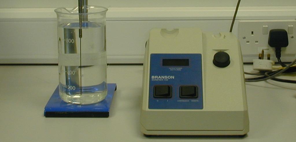
66 & :!! "#$ %% &"" 3.1 Introduction to Apparatus Design )< ),* 5 B,*
67 ,*" ) Performance Characteristic Specification Justification Frequency of Operation khz Typical values used in clinical applications in the literature [7, 21, 51] Wire waveguide diameter 0.35mm -1.0mm Access to peripheral and coronary arteries, similar to standard guidewire dimensions and those reported in the literature [51] Wire waveguide distal-tip displacement Up to 100m peakto-peak Typical values used in clinical applications in the literature [7, 21, 51] Wire waveguide length Up to 500mm Allow for the testing of a range of lengths
68 =0 = =: " 7 7 B) =9 <4 = E =1 6 + # = # < B,*& 5
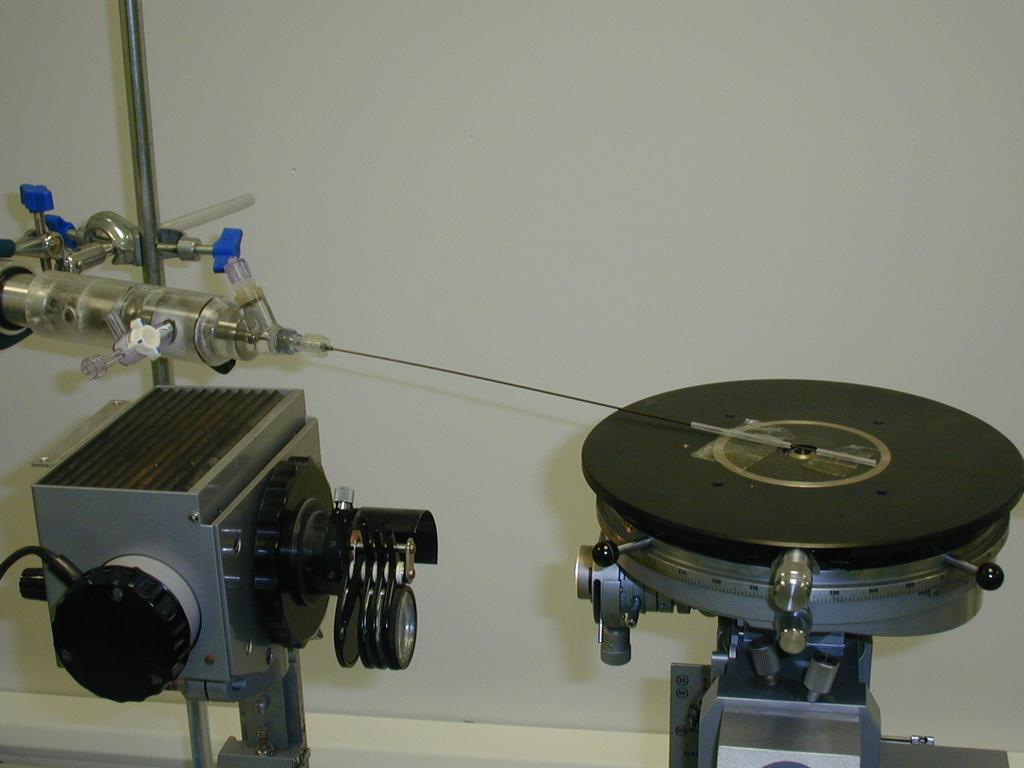
69 3.2 Ultrasonic Wire Waveguide Apparatus Design and Development <*-+S &" S%3* ; =" <#' Ultrasonic generator and converter %G-+@ '..-/0ID4MF+N ) ) B,. ) # ) [ )% ' A= ) M-3N


70 A8& B,. &" $ 0 %0 '..-/ 0 B,,MF+N
71 3.2.2 Acoustic Horn 5 E %&S: - ' *++2 )..- / 0 0 MF*N B,3 ) MF+N B, Wire Waveguide Design! %!' B 7 : R %GD+G;B 7! 3D1+G' < MF.F,N NiTi Wire Waveguide -D47 %X3,47 '7 %#' *+ + =MF3N / *D- + =
 : 9? Q) < +?")
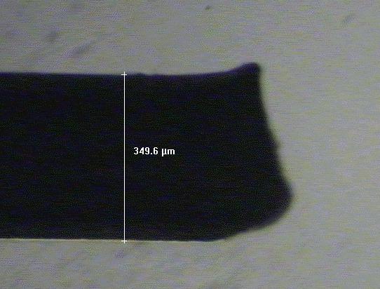
72 MF3N! *+ +D +,- *+ +D +,- ) : 9? Q) < +?4 = B,, 0 " =


73 4 B,3 # / & - B,-# # / = Tensile testing of NiTi wire waveguide < +,- +D 5 Q*' 9? : % '.',' 7 / R /.+T7. [ %.+ + =' +,- B,D MF.F,F-N
74 & MF,N % ' 9? XF-$ % +14' # D++: % ' # D4E 9? X,+$ % ' +D B,F % L1-4' *+4 +*D4 %Y+14' 9? F-$E *3++: Material density of NiTi waveguide # )! AVR < : T D331[, 9??! MF-N
75 3.2.4 Connection of wire waveguide to acoustic horn ) #..-/0 ) $ ID4 ) 1.40E E E+09 Austenitic Transformation Martensitic Stress Pa) 8.00E E E E E Strain B,D< +,-!
76 1.80E E E+09 Stress Pa) 1.20E E E E+08 Cycle 1 Cycle 2 Cycle E E E Strain
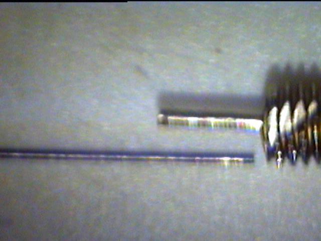
77 B,F= +D! ) 0 ) Evaluation of wire waveguide connection method # *+ +D +,- ) MF+N B,1 B *-,+

78 *- B,G & > - " B,1 J


79 - 4 & ; ; B,G # Q ;
80 Single side set-screw. *+ :. B,*+B,** B,** B %,- 3- ' %D+ 1+ ' # & F+ %A S; = >D+*?' B,*. %L-' 7 B,*, %L*-' B B,*, *+ % ' +D +,-

81 B,*+ 4A - #: ; ; 0 * B,**
82 45 Time to Failure Single Side Set-screw) Time Seconds) Wire Waveguide Diameter mm) B,*.

83 A A & 4 A A A B,*, +D
84 +,- +D & 7 ) E Double side set-screw B,*3,*- %L-' B,*D #%L*-' B +,-

85 B,*3 4A #1 ; ; 4A B,*-
86 60 Time to Failure Double Side Set-screw) Time Seconds) Wire Waveguide Diameter mm) B,*D
87 +,- +D *+ E Axial set-screw D+ :, B,*F,*1 %L-' B,*G # # %L*3' B,.+ %L*', E B,*1 *+ %L,',++ +,- +D D+

88 B,*F A & 4A A A A 0# A A B,*1 *+
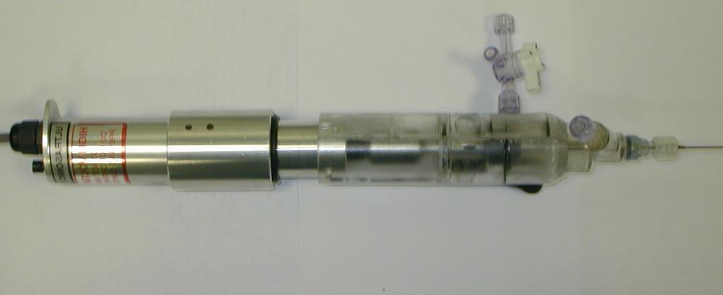
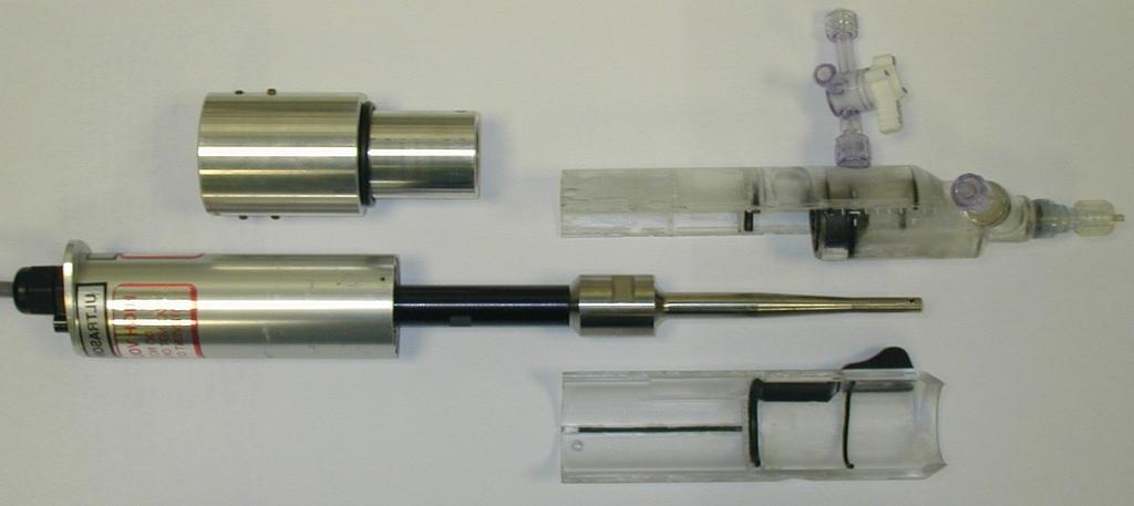
89 +,- +D B,.* %A R ; = >D+*?'E B,.3 B Final apparatus design and housing & # B,.. 5 # 5 # 5? B,., B,++ B,.3 +,-
90
 300 250 Time Seconds) 200")
 B,*G @")
91 350 Time to Failure Axial Crimped Set-screw) Time Seconds) Wire Waveguide Diameter mm) 6A ; < 46A B,.+ +D

92 < #: B,.* +,- # % '
93 B,.. Figure 3.21: Detailed drawing of ultrasonic wire waveguide apparatus
94 &! ; B,.,
95 350 Time to Failure in Housing Time Seconds) mm 0.35mm with sleeve 0.6mm 1.0mm Connection Method B,.3
96 3.3 Summary #! 5 *+,++ *+ # 7 +D +,- G+ +,- # = D ) ) = 3-
97 & 9 #'#$ %% &"" 4.1. Introduction ) =, 5 ) )
98
99 4.2. Direct peak-to-peak displacement measurement ) = B3* Displacement measurement technique " ) E B3. 7 E B3. G<A L'A B3, %<< ' %@ >@$ =3++?'= % #< &' 5 1+
100 ; ; 6+ + A & &A A B3* = + = 6! 6! + = 4 C 4 C B3.<
101 Calibration of Objective Lenses = %T ;R >< :?' 7 5 = B B & D+ * B 3-.+K.+K *GG1K %\' +*1K < D+K -G1.%\+.,K '*++K GG13K %\+..K ' %\ +.,K ' D+K GGF4 %,\' I +DGK

102 6+ & & B3, =
 B3-/.+K % *GG1K \+*1K '")
103 B33.+*++ 10 Histogram of Displacement Measurement 9 Number of Measurements Displacement m) B3-/.+K % *GG1K \+*1K '
104 4.3. Wire Waveguide Distal-Tip Peak-to-Peak Displacements " 5 3+ B3D B3F *+ B *+ *+ +D +,- B, Effect of input power dial settings *+ B31 < E K
105 ; + B3D
106 B3F
107 Distal-Tip Displacement µm p-p) Input Power Dial-Setting Length =298mm Length = 278mm Length = 258mm Length = 228mm B31 *+ *
108 Effects of Wire Waveguide Length J **1,+, - *+ *- B3G.1,,3K.D, -.K # %.-1 *11 ' %.11.*1 ' B3G ) & ) " %' ) 3* ).,- / 0 3* f nc = GC@9@M@NK %3*' 4 l n
109 90 Output peak-to-peak Displacement µm) Wire Length mm) B3G7 **1,+, *- 3*= ).,-/ 0 n Analytical Experimental Percentage Lengths mm) Lengths mm) Error %)
110 ) F. F+ ).,-/ 0 / ) ).* ) " B3*+ & 0 *- %GC',.K # 3.
111 90 Power Setting = 1.5 Output peak-to-peak Displacement µm) y = x Analytical Non- Resonant Lengths Linear Line AA) Wire Length mm) B3*+7 **1,+, ) : ) /
112 ...-.-*+ B3**& 3. * *+ : *K 33-K 3DK
113 Output peak-to-peak Displacement µm) Power Setting = 2 Power Setting = 2.25 Power Setting = 2.5 Linear Trend 2) Linear Trend 2.25) Linear Trend 2.5) Wire Length mm) B3**7 **1,+, 3.= Power Setting Linear Fit y-intercept R-Squared of Linear Fit Exponential Fit y-intercept R-Squared of Exponential Fit Displacement results along length of wire waveguide " ) 3. %'
114 %GC' %G' ωx ωl ωx u x, t) = bcos + tan sin )sinωt %3.' c c c.11 B ).,-/0,.K B 3*..11,,*+D*F1.-* F+*3,.*-.11 B ).11,+,.F, # B3*,# *-,.K.11 B3*3 0 %.11.*,*31 ' %.-, *F1 '.F,,+, B3*-
115 .F,,+,.11 E ),-
116 Internal Displacements p-p) Displacement m) Distance mm) B3*.#.11 5,.K.,-/ 0! %'

117 B3*, G.K D,*FK -3K
118 Displacements p-p) along wire waveguide Displacements m p-p) Distance mm) B3*3.11 *-% L,.K '
119 Displacements p-p) along wire waveguide 40 Experimental 273mm Experimental 288mm Displacements p-p) Distance mm) B3*-.F, *-% L,.K '
120 Displacements p-p) along wire waveguide 40 Experimental 303mm Experimental 288mm Displacements p-p) Distance mm) B3*-,+, *-% L,.K '
121 4.5. Summary 7 7 / ).,-/0 B &
122 & ) #%% * 5.1 Introduction = 3 E ) 7 =. ) Q! # B
123 =. B ) = 3 E < : MD.N )< 5.2 Modal Analysis of Wire Waveguide #
124 5.2.1 Modal Analysis Method B-* #! <9<R : %1*'5 & A0 MFDN ) 2 [ K]{ φ } = ω [ M ]{ φ } %-*' i i i [K ] L { φ i } L % ' ω L )% ω 2 ' i i [M ] L
125 8 +,,+,+,+ B-*
126 5.2.2 Effects of Mesh Density on Modal Analysis of Wire Waveguide B-. ). 3) %3.'MFFN 0 0 : % ' %' %' %H'MDDN : ),+, *+ +D +,- 9?! = Sensitivity Analysis of Material Properties B 9? I-4 = 3 = 3

127 B-. *+.HD+D. B-. *+.H,+, 3
128 5.2.4 Results of Modal Analysis ),+, -*)+,+/0 ) ) B-, ) B %*H*+' ) ) *H- B *+ B-, * H*+ ) 7 ) *H.++ ).HD+D B-.. 3 *+ -, B-,B-, +D +,-
129 -*= #! ; B),+, Resonant Frequency Analytical Resonant Frequency Solution Hz) Numerical Resonant Frequency Predictions Hz) % Error) 1.0mm 0.6mm 0.35mm 0.03%) %) %) %) %) %) %) %) %) %) %) %) %) %) %) B.HG+G +D, 3 < +,-.H*.*. 3
130 Summary of Modal Analysis -* ) ) ++,4 ) B-3 9? I-4 ) 5 )
131 Frequency Hz) st Resonant Frequency 2nd Resonant Frequency 3rd Resonant Frequency 4th Resonant Frequency 5th Resonant Frequency Mesh Density r y) B-,: *+,+,
132 Frequency Hz) st Resonant Frequency 2nd Resonant Frequency 3rd Resonant Frequency 4th Resonant Frequency 5th Resonant Frequency Mesh Density r y) B-,: +D,+,
133 Frequency Hz) st Resonant Frequency 2nd Resonant Frequency 3rd Resonant Frequency 4th Resonant Frequency 5th Resonant Frequency Mesh Density r y) B-,: +,-,+,
134 st Resonant Frequency 5th Resonant Frequency Frequency Hz) %) %) Young's Modulus Gpa) B-3 ) %I-4'9? L,+, st Resonant Frequency 5th Resonant Frequency Frequency Hz) %) %) Density kg/m^3) B-3 ) %I-4' L,+,
135 5.3 Harmonic Response Analysis of Wire Waveguide # ) MDFN ) ) ) = 3 ) Harmonic response method # ) MDFN [ M ] u) + [ C] u) + [ K] u) = F a ) %-.' [M ] L [K ] L a F ) L
136 [C] L u ) u ) u ) L [ C] = β )[ K] %-,' β ) ζ ) ) f ) ζ β ) = %-3' πf B-- # G!!$$ )
137 5.3.2 Distal-tip response of wire waveguides over a range of frequencies ) +,+/0 ) : *+ +D +,- ) Distal-tip response of wire waveguides over a range lengths = 3 : **1,+, - *+ +D +,- ).,-/ 0 ) Displacement response along length of wire waveguides " % ' ).,-/ 0 = 3
138 5.3.5 Wire Waveguides with Spherical Distal-tip Geometry / M.-.-N7 = Results from harmonic response analysis B-D )+J,+/ 0,+K,+, *4 ) ) MD-N B-F *+,+K D+K G+K E *4 ) =, ).,-/0 = 3 B-1
139 7 ) B-G 5 ) J = 3 B )
140 8 +,,-.#,+,+ B--
141 8.00E-04 Distal-tip peak-to-peak displacement m) 7.00E E E E E E E E+00 Diameter = 0.35mm Diameter = 0.6mm Diameter = 1.0mm Frequency Hz) B-D )+J,+/ 0,+K,+, *4
142 5.00E-04 Distal-tip peak-to-peak displacement m) 4.50E E E E E E E E E-05 Input = 30m p-p) Input = 60m p-p) Input = 90m p-p) 0.00E Frequency Hz) B-F *+ )*-J,+/ 0,+K D+K G+ K,+, *4
143 Distal-tip peak-to-peak displacement m) 2.00E E E E E E E E E E-05 Damping = 1% Damping = 2% Damping = 3% Damping = 4% Damping = 5% 0.00E Frequency Hz) B-1 *+ )*1J.1/ 0,+K,+, *4-4
144 Distal-tip peak-to-peak displacement m) 3.00E E E E E E-05 Length = 303mm Length = 283mm Length = 263mm 0.00E Frequency Hz) B-G *+ )*1J.1/ 0,+K.D,.1,,+, *4
145 B-*+ ).,-/0 *+ **1J,+, -,.K *+ *- % ' 3-4 B-** MF,N % ' B-*..- 3DK Q
146 Damping = 4% Distal-tip peak-to-peak Displacement µm) 100 Damping = 4.5% Damping = 5% Wire Length mm) B-*+ *+.,-/ 0 **1 J,+,,.K
147 Distal-tip peak-to-peak Displacement µm) Numerical Experimental Wire Length mm) B-**= *+ **1 J,+,,. K % L*-' 3-4
148 Distal-tip peak-to-peak Displacement µm) Numerical Experimental Wire Length mm) B-*.= *+ **1 J,+, 3D K % L..-' 3-4
149 B-*, *+.11,.K.,-/0 ).*# 3-4 B -*3 %'.11,.K.,-/0 3-4 #.11 B-*, %,.K %'' 0# -*1 : 7 B-*3.1K %'# 0.1:
150 Phase Numerical Analytical Phase Degrees) Distance mm) Internal Displacements p-p) 35 Displacement m) Distance mm) 6.0E+07 Stress 5.0E E+07 Stress Pa) 3.0E E E E Distance mm) B-*,= % ' *+ %L.11 '
151 Phase Phase Degrees) Internal Waveguide Displacements p-p) 35 Numerical Experimental 30 Displacement p-p m) Distance mm) 6.E+07 Internal Waveguide Stress 5.E+07 Stress Pa) 4.E+07 3.E+07 2.E+07 1.E+07 0.E Distance mm) B-*3= % L3-4' *+ %L.11 '
152 Phase 90 Phase Degrees) Internal Waveguide Displacements p-p) 40 Numerical Experimental 35 Displacement p-p) m) Distance mm) 6.E+07 Internal Waveguide Stress 5.E+07 Stress Pa) 4.E+07 3.E+07 2.E+07 1.E+07 0.E Distance mm) B-*-= % L3-4' *+ %L,+, '
153 Phase Phase Degrees) Internal Waveguide Displacements p-p) Numerical Experimental Displacem ent p-p) m ) Distance mm) Internal Waveguide Stress 7.E+07 6.E+07 5.E+07 Stress Pa) 4.E+07 3.E+07 2.E+07 1.E+07 0.E Distance mm) B-*D= % L3-4' *+ %L.F, ' ) %' B *+..!
154 -+-:! =, B-*-,+, ) %' <,D1: -3,: < B-*D.F, ) -..: D3D: *+.F, 3*! # M-3N % ' =,3 B -*F ) +,- -++ *+ *- ) )< MD-N < -3
155 5.3.7 Summary of Harmonic Analysis of Wire Waveguide # 5!
156
157 Distal-Tip Displacement m) No distal-tip 1.0mm Ball-tip 1.5mm Ball-tip Frequency Hz) B-*F= ) +,- %L-++ ' *++K Coupled Fluid-Structure Model of Wire Waveguide
158 < : MD.N ) Acoustic Fluid-Structure Method MD1N) % ) -.' < [ M ] u) + [ K ] u) = F ) + [ R] P) S S S %--' T B M ] P) + [ K ] P) = F ) ρ [ R] u) [ F F F 0 P ) P ) L. M&NL ) ) -- ) ) ) -D
159 = M ρ 0 R S T 0 M F u K S + P 0 R u F = K F P F S F %-D' B #.G%. 3 ' %B<' # # *.G%. 3 ' B-*1 % & % ' 7 P = + %-F' max 2 2 P R PI
160 A < A B-*1<! B< : Fluid-structure model of spherical distal-tip # +,- -++ *+ *- %X*-1+ *' %X*+-+, 'MF1N
161 +,- *+ B -*G MD+N B-.+ %' *+ # >+C? >+;? *+*- B-.*B-.. ) *- 0

162 < $ % < $<% ; ; < $; % B-*G < # B< : 7 7 *+

163 5 > B-.+ %' *+ D3-K.,-/ 0
164 Distal-Tip Displacement p-p m) No Distal Fluid 100m With Distal Fluid 100m With Distal Fluid 150m Frequency Hz) B-.*= ) +,-%L-++' *+ *++K*-+K%'
165 Distal-Tip Displacement p-p m) No Distal Fluid With fluid 100m With fluid 150m Frequency Hz) B-..= ) +,- %L-++ ' *- *++K *-+K %' %>+C?' % ' +,- *+ B-., ) -1MD+N*+ %D3-2 ')%.,- / 0'
166 P max 2 R cosθ 2 2 = 2π ρrf d 0 %-1' 2 r * [. B.*. ) -GM-FN.11/ ) *++.++M-3-1N T 2 Pm = %-G' 2ρc B-.3 >+C? B -.- >+;? *+ *- %'
167 m Numerical 64.5m Analytical Pressure Pa) Distance from distal-tip mm) B-.,= >+C? *+ D3-K.,-/0
168 m, 1.0mm tip m, 1.0mm tip Pressure Pa) m, 1.5mm tip 76m, 1.5mm tip Cavitation Threshold 2.5W/cm^2) Distance mm) B-.3= >+C? *+ *-.,-/ 0 = %.-7 [. '
169 Pressure Pa) m, 1.0mm tip 95m, 1.0mm tip 51m, 1.5mm tip 76m, 1.5mm tip Cavitation Threshold 2.5W/cm^2) Distance mm) B-.-= >+;? *+ *-.,-/ 0 = %.-7 [. '
170 B-.D, +,- *- -*2 < MD.N & B-.F B-.F : MD.NB-.1 *. *: : MD.N,! # D-2 B -.G 5 &

171 B-.D % ' *- -*K.,-/ 0

172 B-.F %'.3D *,+K..-/ 0 : MD.N
173 Experimental, Makin [62] Numerical Pressure Pa) Distance mm) B-.1= : MD.N
174 ' Pressure [Pa] '

175 B-.G= ' : MD.N' % LD-2 %'' %O*. ' & Fluid-structure model of wire waveguide with no distal-tip # +,- B-,+B-,* **.D--1+2 B-,. B-,,
176 # *+ B -,3 *+ D B -,+ ) [. M-3N
177 B-,* %'+,- %)L.,-/ 0 L**2 ' µm 26µm 55µm 80µm Pressure Pa) Distance from distal-tip mm) B-,.= %+,- '.,-/ 0

178 B-,, % L1+2 %'' +,-
179 um p-p) Pressure Pa) ump-p) 27ump-p) Cavitation Threshold 2.5W/cm^2) Distance mm) B-,3= %*+ '.,-/ 0= %.-7 [. '
180 5.5 Summary # 3-4 ) % ' : MD.N )
181 & 1 " /#$ % % &"" 6.1 Introduction & *+ =,! +,- = -
182 6.2 Tapered Wire Waveguide #! *+ +,- B D* 7 = %*+.,+<7 <= E " <#'! =,,*+ & *+ +,- *+.11 BD. = 3! +,- % ' # +,- BD, : MD.N +3
183 # #: BD* +,-
184 80 70 Distal-Tip Displacement µm p-p) Input Power Dial Setting BD. *+.11

185 BD, +,- 5 1
186 6.3 Model Materials = %' MF1N< %@#' MF1FG% MDN'N ) & =; $= " =%E/' !M1+N= % ' BD3 5 <MD.+N& ;&;= = / /.+T7.[ BD- -+! B DD 9? D+: F+: )<MD.+NB.,%*3' 3*D:
187 9? * *+++: M1* 1.% D'3G1,N

188 &&! &- BD3&
189 Strain ,000,000-4,000,000 Stress Pa) -6,000,000-8,000,000-10,000,000-12,000,000-14,000,000-16,000,000 Calc. Carb. 1 Calc. Carb. 2 20kN Calc. Hydr. 40kN Calc. Hydr. 50kN Calc. Hydr. -18,000,000 BD-; %L.' %.+3+-+!'
190 0 Strain ,000,000 Stress Pa) -2,000,000-3,000,000-4,000,000-5,000,000-6,000,000 Slope = 60 MPa R 2 = Slope = 70 MPa R 2 = Calc. Carb. 1 Calc. Carb. 2 Linear Calc. Carb. 2) Linear Calc. Carb. 1) BDD=
191 6.4 Testing Ultrasonic Wire Waveguide Apparatus on Model Materials =, BDFBD1 %.$ %.'.G!.O $.. +-! B [ BDGBD*+ %.'*! BD** BD*..! #,-.1. [ -* [ -+!
192 Fc Fr Fa Specimen Slider/ Holder Nylon) Table-top Steel) W =mg N) Waveguide and horn BDF
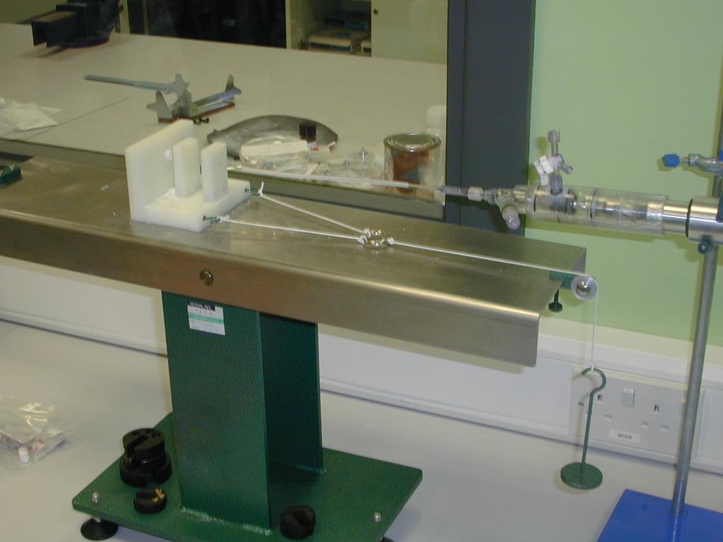
193 BD1#
MECHANICAL PROPERTIES OF MATERIALS
 MECHANICAL PROPERTIES OF MATERIALS! Simple Tension Test! The Stress-Strain Diagram! Stress-Strain Behavior of Ductile and Brittle Materials! Hooke s Law! Strain Energy! Poisson s Ratio! The Shear Stress-Strain
Development and Verification of Multi-Level Sub- Meshing Techniques of PEEC to Model High- Speed Power and Ground Plane-Pairs of PFBS
 Rose-Hulman Institute of Technology Rose-Hulman Scholar Graduate Theses - Electrical and Computer Engineering Graduate Theses Spring 5-2015 Development and Verification of Multi-Level Sub- Meshing Techniques
Robust Network Interdiction with Invisible Interdiction Assets
 University of Arkansas, Fayetteville ScholarWorks@UARK Theses and Dissertations 5-2014 Robust Network Interdiction with Invisible Interdiction Assets Nail Orkun Baycik University of Arkansas, Fayetteville
Statistical analysis of extreme events in a nonstationary context via a Bayesian framework. Case study with peak-over-threshold data
 Statistical analysis of extreme events in a nonstationary context via a Bayesian framework. Case study with peak-over-threshold data B. Renard, M. Lang, P. Bois To cite this version: B. Renard, M. Lang,
 katoh@kuraka.co.jp okaken@kuraka.co.jp mineot@fukuoka-u.ac.jp 4 35 3 Normalized stress σ/g 25 2 15 1 5 Breaking test Theory 1 2 Shear tests Failure tests Compressive tests 1 2 3 4 5 6 Fig.1. Relation between
Strain gauge and rosettes
 Strain gauge and rosettes Introduction A strain gauge is a device which is used to measure strain (deformation) on an object subjected to forces. Strain can be measured using various types of devices classified
Figure 1 - Plan of the Location of the Piles and in Situ Tests
 Figure 1 - Plan of the Location of the Piles and in Situ Tests 1 2 3 A B C D DMT4 DMT5 PMT1 CPT4 A 2.2 1.75 S5+ SPT CPT7 CROSS SECTION A-A C2 E7 E5 S4+ SPT E3 E1 E DMT7 T1 CPT9 DMT9 CPT5 C1 ground level
Follow this and additional works at:
 Indiana University - Purdue University Fort Wayne Opus: Research & Creativity at IPFW Manufacturing & Construction Engineering Technology and Interior Design Senior Design Projects School of Engineering,
Chapter 7 Transformations of Stress and Strain
 Chapter 7 Transformations of Stress and Strain INTRODUCTION Transformation of Plane Stress Mohr s Circle for Plane Stress Application of Mohr s Circle to 3D Analsis 90 60 60 0 0 50 90 Introduction 7-1
(Mechanical Properties)
") 109101 Engineering Materials (Mechanical Properties-I) 1 (Mechanical Properties) Sheet Metal Drawing / (- Deformation) () 3 Force -Elastic deformation -Plastic deformation -Fracture Fracture 4 Mode of
109101 Engineering Materials (Mechanical Properties-I) 1 (Mechanical Properties) Sheet Metal Drawing / (- Deformation) () 3 Force -Elastic deformation -Plastic deformation -Fracture Fracture 4 Mode of
Note: Please use the actual date you accessed this material in your citation.
 MIT OpenCourseWare http://ocw.mit.edu 6.03/ESD.03J Electromagnetics and Applications, Fall 005 Please use the following citation format: Markus Zahn, 6.03/ESD.03J Electromagnetics and Applications, Fall
RSDW08 & RDDW08 series
 /,, MODEL SELECTION TABLE INPUT ORDER NO. INPUT VOLTAGE (RANGE) NO LOAD INPUT CURRENT FULL LOAD VOLTAGE CURRENT EFFICIENCY (Typ.) CAPACITOR LOAD (MAX.) RSDW08F-03 344mA 3.3V 2000mA 80% 2000μF RSDW08F-05
NPI Unshielded Power Inductors
 FEATURES NON-SHIELDED MAGNETIC CIRCUIT DESIGN SMALL SIZE WITH CURRENT RATINGS TO 16.5 AMPS SURFACE MOUNTABLE CONSTRUCTION TAKES UP LESS PCB REAL ESTATE AND SAVES MORE POWER TAPED AND REELED FOR AUTOMATIC
Multilayer Ceramic Chip Capacitors
 FEATURES X7R, X6S, X5R AND Y5V DIELECTRICS HIGH CAPACITANCE DENSITY ULTRA LOW ESR & ESL EXCELLENT MECHANICAL STRENGTH NICKEL BARRIER TERMINATIONS RoHS COMPLIANT SAC SOLDER COMPATIBLE* PART NUMBER SYSTEM
DETERMINATION OF DYNAMIC CHARACTERISTICS OF A 2DOF SYSTEM. by Zoran VARGA, Ms.C.E.
 DETERMINATION OF DYNAMIC CHARACTERISTICS OF A 2DOF SYSTEM by Zoran VARGA, Ms.C.E. Euro-Apex B.V. 1990-2012 All Rights Reserved. The 2 DOF System Symbols m 1 =3m [kg] m 2 =8m m=10 [kg] l=2 [m] E=210000
TRIAXIAL TEST, CORPS OF ENGINEERS FORMAT
 TRIAXIAL TEST, CORPS OF ENGINEERS FORMAT .5 C, φ, deg Tan(φ) Total.7 2.2 Effective.98 8.33 Shear,.5.5.5 2 2.5 3 Total Normal, Effective Normal, Deviator,.5.25.75.5.25 2.5 5 7.5 Axial Strain, % Type of
SMD Transient Voltage Suppressors
 SMD Transient Suppressors Feature Full range from 0 to 22 series. form 4 to 60V RMS ; 5.5 to 85Vdc High surge current ability Bidirectional clamping, high energy Fast response time
ΙΕΥΘΥΝΤΗΣ: Καθηγητής Γ. ΧΡΥΣΟΛΟΥΡΗΣ Ι ΑΚΤΟΡΙΚΗ ΙΑΤΡΙΒΗ
 ΠΑΝΕΠΙΣΤΗΜΙΟ ΠΑΤΡΩΝ ΠΟΛΥΤΕΧΝΙΚΗ ΣΧΟΛΗ ΤΜΗΜΑ ΜΗΧΑΝΟΛΟΓΩΝ ΚΑΙ ΑΕΡΟΝΑΥΠΗΓΩΝ ΜΗΧΑΝΙΚΩΝ ΕΡΓΑΣΤΗΡΙΟ ΣΥΣΤΗΜΑΤΩΝ ΠΑΡΑΓΩΓΗΣ & ΑΥΤΟΜΑΤΙΣΜΟΥ / ΥΝΑΜΙΚΗΣ & ΘΕΩΡΙΑΣ ΜΗΧΑΝΩΝ ΙΕΥΘΥΝΤΗΣ: Καθηγητής Γ. ΧΡΥΣΟΛΟΥΡΗΣ Ι ΑΚΤΟΡΙΚΗ
Second Order RLC Filters
 ECEN 60 Circuits/Electronics Spring 007-0-07 P. Mathys Second Order RLC Filters RLC Lowpass Filter A passive RLC lowpass filter (LPF) circuit is shown in the following schematic. R L C v O (t) Using phasor
Design and Fabrication of Water Heater with Electromagnetic Induction Heating
 U Kamphaengsean Acad. J. Vol. 7, No. 2, 2009, Pages 48-60 ก 7 2 2552 ก ก กก ก Design and Fabrication of Water Heater with Electromagnetic Induction Heating 1* Geerapong Srivichai 1* ABSTRACT The purpose
Multilayer Ceramic Chip Capacitors
 FEATURES X7R, X6S, X5R AND Y5V DIELECTRICS HIGH CAPACITANCE DENSITY ULTRA LOW ESR & ESL EXCELLENT MECHANICAL STRENGTH NICKEL BARRIER TERMINATIONS RoHS COMPLIANT SAC SOLDER COMPATIBLE* Temperature Coefficient
Daewoo Technopark A-403, Dodang-dong, Wonmi-gu, Bucheon-city, Gyeonggido, Korea LM-80 Test Report
 LM-80 Test Report Approved Method: Measuring Lumen Maintenance of LED Light Sources Project Number: KILT1212-U00216 Date: September 17 th, 2013 Requested by: Dongbu LED Co., Ltd 90-1, Bongmyeong-Ri, Namsa-Myeon,
Electronic Supplementary Information (ESI)
") Electronic Supplementary Material (ESI) for RSC Advances. This journal is The Royal Society of Chemistry 2016 Electronic Supplementary Information (ESI) Cyclopentadienyl iron dicarbonyl (CpFe(CO) 2 ) derivatives
Electronic Supplementary Material (ESI) for RSC Advances. This journal is The Royal Society of Chemistry 2016 Electronic Supplementary Information (ESI) Cyclopentadienyl iron dicarbonyl (CpFe(CO) 2 ) derivatives
NMBTC.COM /
 Common Common Vibration Test:... Conforms to JIS C 60068-2-6, Amplitude: 1.5mm, Frequency 10 to 55 Hz, 1 hour in each of the X, Y and Z directions. Shock Test:...Conforms to JIS C 60068-2-27, Acceleration
Type 947D Polypropylene, High Energy Density, DC Link Capacitors
 Type 947D series uses the most advanced metallized film technology for long life and high reliability in DC Link applications. This series combines high capacitance and very high ripple current capability
Type C Aluminum Electrolytic, Screw Terminal Best Value 85 C High Capacitance Screw Terminal Type
 Type 386 85 C Aluminum Electrolytic, Screw Terminal While Type 386 s standard encasement is by compression with the capacitor element captured on an aluminum peg in the can bottom and a phenolic peg in
Rational Ligand Design for Potential Applications in Transition Metal Catalysis
 University of Missouri, St. Louis IRL @ UMSL Dissertations UMSL Graduate Works 10-25-2011 Rational Ligand Design for Potential Applications in Transition Metal Catalysis Sergey L. Sedinkin University of
Computing the Gradient
 FMIA F. Moukalled L. Mangani M. Darwish An Advanced Introduction with OpenFOAM and Matlab This textbook explores both the theoretical oundation o the Finite Volume Method (FVM) and its applications in
Bulletin 1489 UL489 Circuit Breakers
 Bulletin 489 UL489 Circuit Breakers Tech Data 489-A Standard AC Circuit Breaker 489-D DC Circuit Breaker 489-A, AC Circuit Breakers 489-D, DC Circuit Breakers Bulletin 489-A Industrial Circuit Breaker
ZLW Series. Single-stage Monoblock Centrifugal Pump ZL PUMP GROUP.,LTD
 ZLW Series Single-stage Monoblock Centrifugal Pump ZL PUMP GROUP.,LTD 1 Application Apply as the transportation of liquids in the fields of air condition, heating, sanitary water, water treatment cooling,
Correction of chromatic aberration for human eyes with diffractive-refractive hybrid elements
 5 5 2012 10 Chinese Optics Vol. 5 No. 5 Oct. 2012 1674-2915 2012 05-0525-06 - * 100190-14 - - 14. 51 μm 81. 4 μm - 1. 64 μm / O436. 1 TH703 A doi 10. 3788 /CO. 20120505. 0525 Correction of chromatic aberration
Design Method of Ball Mill by Discrete Element Method
 Design Method of Ball Mill by Discrete Element Method Sumitomo Chemical Co., Ltd. Process & Production Technology Center Makio KIMURA Masayuki NARUMI Tomonari KOBAYASHI The grinding rate of gibbsite in
SMC SERIES Subminiature Coaxial Connectors
 SERIES Subminiature Coaxial Connectors FEATURES Subminiature coaxial connectors with 50 Ω impedance for applications up to 10 GHz. (screw on mechanism)fulfills the subminiature coaxial connector requirement
Decision-Making in the Dark: How Pre-Trial Errors Change the Narrative in Criminal Jury Trials
 Chicago-Kent Law Review Volume 90 Issue 3 Juries and Lay Participation: American Perspectives and Global Trends Article 8 6-23-2015 Decision-Making in the Dark: How Pre-Trial Errors Change the Narrative
Metal Oxide Varistors (MOV) Data Sheet
 Data Sheet") Φ SERIES Metal Oxide Varistors (MOV) Data Sheet Features Wide operating voltage (V ma ) range from 8V to 0V Fast responding to transient over-voltage Large absorbing transient energy capability Low clamping
Φ SERIES Metal Oxide Varistors (MOV) Data Sheet Features Wide operating voltage (V ma ) range from 8V to 0V Fast responding to transient over-voltage Large absorbing transient energy capability Low clamping
Metal Film Leaded Precision Resistor
 Features Excellent overall stability Very tight tolerance down to ±0.05% Extremely low TCR down to ±5 PPM/ C High power rating up to 3 Watts Excellent ohmic contact Construction Applications Telecommunication
Shenzhen Lys Technology Co., Ltd
 Carbide drawing dies Properties of grade Grade Density TRS Average Grain size Hardness (HRA) (g/cm3) (MPa) (ųm) YL01 15.25 93.5 3300 0.8 YL10.2 14.5 92.0 4000 0.8 YG6 14.95 90 2400 1.6 YG6X 14.95 91.5
SMC SERIES Subminiature Coaxial Connectors
 SERIES Subminiature Coaxial Connectors FEATURES Subminiature coaxial connectors with 50 Ω impedance for applications up to 10 GHz. (screw on mechanism)fulfills the subminiature coaxial connector requirement
Surface Mount Multilayer Chip Capacitors for Commodity Solutions
 Surface Mount Multilayer Chip Capacitors for Commodity Solutions Below tables are test procedures and requirements unless specified in detail datasheet. 1) Visual and mechanical 2) Capacitance 3) Q/DF
Metal Film Leaded Precision Resistor
 Power ratio(%) MFR Series Features Excellent overall stability Very tight tolerance down to ±0.05% Extremely low TCR down to ±5 PPM/ C High power rating up to 3 Watts Excellent ohmic contact Applications
CorV CVAC. CorV TU317. 1
 30 8 JOURNAL OF VIBRATION AND SHOCK Vol. 30 No. 8 2011 1 2 1 2 2 1. 100044 2. 361005 TU317. 1 A Structural damage detection method based on correlation function analysis of vibration measurement data LEI
Lifting Entry (continued)
") ifting Entry (continued) Basic planar dynamics of motion, again Yet another equilibrium glide Hypersonic phugoid motion Planar state equations MARYAN 1 01 avid. Akin - All rights reserved http://spacecraft.ssl.umd.edu
ifting Entry (continued) Basic planar dynamics of motion, again Yet another equilibrium glide Hypersonic phugoid motion Planar state equations MARYAN 1 01 avid. Akin - All rights reserved http://spacecraft.ssl.umd.edu
Written Examination. Antennas and Propagation (AA ) April 26, 2017.
 April 26, 2017.") Written Examination Antennas and Propagation (AA. 6-7) April 6, 7. Problem ( points) Let us consider a wire antenna as in Fig. characterized by a z-oriented linear filamentary current I(z) = I cos(kz)ẑ
Written Examination Antennas and Propagation (AA. 6-7) April 6, 7. Problem ( points) Let us consider a wire antenna as in Fig. characterized by a z-oriented linear filamentary current I(z) = I cos(kz)ẑ
AT Surface Mount Package SOT-363 (SC-70) I I Y. Pin Connections B 1 C 1 E 1 E 2 C 2 B , 7:56 PM
 I I Y. Pin Connections B 1 C 1 E 1 E 2 C 2 B , 7:56 PM") AT-3263 Surface Mount Package SOT-363 (SC-7) I I Y Pin Connections B 1 C 1 E 1 E 2 C 2 B 2 Page 1 21.4., 7:6 PM Absolute Maximum Ratings [1] Absolute Thermal Resistance [2] : Symbol Parameter Units Maximum
AT-3263 Surface Mount Package SOT-363 (SC-7) I I Y Pin Connections B 1 C 1 E 1 E 2 C 2 B 2 Page 1 21.4., 7:6 PM Absolute Maximum Ratings [1] Absolute Thermal Resistance [2] : Symbol Parameter Units Maximum
Finish: Anticorrosive finish in polyester. Number of motor poles 4=1400 r/min. 50 Hz 6=900 r/min. 50 Hz 8=750 r/min. 50 Hz
 HEP HEPT HEP: Wall-mounted axial fans, with IP65 motor HEPT: Long-cased axial fans, with IP65 motor Wall-mounted axial (HEP) and long-cased (HEPT) fans, with fibreglass-reinforced plastic impeller. Fan:
0.635mm Pitch Board to Board Docking Connector. Lead-Free Compliance
 .635mm Pitch Board to Board Docking Connector Lead-Free Compliance MINIDOCK SERIES MINIDOCK SERIES Features Specifications Application.635mm Pitch Connector protected by Diecasted Zinc Alloy Metal Shell
C4C-C4H-C4G-C4M MKP Series AXIAL CAPACITORS PCB APPLICATIONS
 C4C-C4H-C4G-C4M AXIAL CAPACITORS PCB APPLICATIONS General characteristics - Self-Healing - Low losses - High ripple current - High contact reliability - Suitable for high frequency applications 40 ±5 L
Multilayer Chip Inductor
 Features -Monolithic structure for high reliability -High self-resonant frequency -Excellent solderability and high heat resistance Construction Applications -RF circuit in telecommunication and other
Coupling of a Jet-Slot Oscillator With the Flow-Supply Duct: Flow-Acoustic Interaction Modeling
 1th AIAA/CEAS Aeroacoustics Conference, May 006 interactions Coupling of a Jet-Slot Oscillator With the Flow-Supply Duct: Interaction M. Glesser 1, A. Billon 1, V. Valeau, and A. Sakout 1 mglesser@univ-lr.fr
Thin Film Chip Resistors
 FEATURES PRECISE TOLERANCE AND TEMPERATURE COEFFICIENT EIA STANDARD CASE SIZES (0201 ~ 2512) LOW NOISE, THIN FILM (NiCr) CONSTRUCTION REFLOW SOLDERABLE (Pb FREE TERMINATION FINISH) Type Size EIA PowerRating
Απόκριση σε Μοναδιαία Ωστική Δύναμη (Unit Impulse) Απόκριση σε Δυνάμεις Αυθαίρετα Μεταβαλλόμενες με το Χρόνο. Απόστολος Σ.
 Απόκριση σε Δυνάμεις Αυθαίρετα Μεταβαλλόμενες με το Χρόνο. Απόστολος Σ.") Απόκριση σε Δυνάμεις Αυθαίρετα Μεταβαλλόμενες με το Χρόνο The time integral of a force is referred to as impulse, is determined by and is obtained from: Newton s 2 nd Law of motion states that the action
Απόκριση σε Δυνάμεις Αυθαίρετα Μεταβαλλόμενες με το Χρόνο The time integral of a force is referred to as impulse, is determined by and is obtained from: Newton s 2 nd Law of motion states that the action
 22 .5 Real consumption.5 Real residential investment.5.5.5 965 975 985 995 25.5 965 975 985 995 25.5 Real house prices.5 Real fixed investment.5.5.5 965 975 985 995 25.5 965 975 985 995 25.3 Inflation
ISM 868 MHz Ceramic Antenna Ground cleared under antenna, clearance area mm x 8.25 mm. Pulse Part Number: W3013
 W0 Datasheet version.. Ceramic Antenna. (0/08). Ceramic Antenna Ground cleared under antenna, clearance area 0.80 mm x 8.5 mm. Pulse Part Number: W0 Features - Omni directional radiation - Low profile
EXPERIMENTAL AND NUMERICAL STUDY OF A STEEL-TO-COMPOSITE ADHESIVE JOINT UNDER BENDING MOMENTS
 NATIONAL TECHNICAL UNIVERSITY OF ATHENS SCHOOL OF NAVAL ARCHITECTURE AND ARINE ENGINEERING SHIPBUILDING TECHNOLOGY LABORATORY EXPERIENTAL AND NUERICAL STUDY OF A STEEL-TO-COPOSITE ADHESIVE JOINT UNDER
YJM-L Series Chip Varistor
 Features 1. RoHS & Halogen Free (HF) compliant 2. EIA size: 0402 ~ 2220 3. Operating voltage: 5.5Vdc ~ 85Vdc 4. High surge suppress capability 5. Bidirectional and symmetrical V/I characteristics 6. Multilayer
Monolithic Crystal Filters (M.C.F.)
") Monolithic Crystal Filters (M.C.F.) MCF (MONOLITHIC CRYSTAL FILTER) features high quality quartz resonators such as sharp cutoff characteristics, low loss, good inter-modulation and high stability over
Monolithic Crystal Filters (M.C.F.) MCF (MONOLITHIC CRYSTAL FILTER) features high quality quartz resonators such as sharp cutoff characteristics, low loss, good inter-modulation and high stability over
Reforming the Regulation of Political Advocacy by Charities: From Charity Under Siege to Charity Under Rescue?
 Chicago-Kent Law Review Volume 91 Issue 3 Nonprofit Oversight Under Siege Article 9 7-1-2015 Reforming the Regulation of Political Advocacy by Charities: From Charity Under Siege to Charity Under Rescue?
DERIVATION OF MILES EQUATION FOR AN APPLIED FORCE Revision C
 DERIVATION OF MILES EQUATION FOR AN APPLIED FORCE Revision C By Tom Irvine Email: tomirvine@aol.com August 6, 8 Introduction The obective is to derive a Miles equation which gives the overall response
SC Style Optical Connector
 SC Style Optical Connector OUTLINE SC connector is a push/pull style connector developed by NTT. The square, snap-in connector latches with a simple push-pull motion and is keyed. It is frequently used
Συγκριτική Αξιολόγηση Προσοµοιωµάτων Τοιχείων και Πυρήνων Κτηρίων µε τη Μέθοδο των Πεπερασµένων Στοιχείων και Πειραµατικά Αποτελέσµατα
 Συγκριτική Αξιολόγηση Προσοµοιωµάτων Τοιχείων και Πυρήνων Κτηρίων µε τη Μέθοδο των Πεπερασµένων Στοιχείων και Πειραµατικά Αποτελέσµατα Experimental verification of shear wall modeling using finite element
Evolution of Novel Studies on Thermofluid Dynamics with Combustion
 MEMOIRS OF SHONAN INSTITUTE OF TECHNOLOGY Vol. 42, No. 1, 2008 * Evolution of Novel Studies on Thermofluid Dynamics with Combustion Hiroyuki SATO* This paper mentions the recent development of combustion
Sampling Basics (1B) Young Won Lim 9/21/13
 Young Won Lim 9/21/13") Sampling Basics (1B) Copyright (c) 2009-2013 Young W. Lim. Permission is granted to copy, distribute and/or modify this document under the terms of the GNU Free Documentation License, Version 1.2 or any
Sampling Basics (1B) Copyright (c) 2009-2013 Young W. Lim. Permission is granted to copy, distribute and/or modify this document under the terms of the GNU Free Documentation License, Version 1.2 or any
Study of In-vehicle Sound Field Creation by Simultaneous Equation Method
 Study of In-vehicle Sound Field Creation by Simultaneous Equation Method Kensaku FUJII Isao WAKABAYASI Tadashi UJINO Shigeki KATO Abstract FUJITSU TEN Limited has developed "TOYOTA remium Sound System"
Creative TEchnology Provider
 1 Oil pplication Capacitors are intended for the improvement of Power Factor in low voltage power networks. Used advanced technology consists of metallized PP film with extremely low loss factor and dielectric
Matrices and Determinants
 Matrices and Determinants SUBJECTIVE PROBLEMS: Q 1. For what value of k do the following system of equations possess a non-trivial (i.e., not all zero) solution over the set of rationals Q? x + ky + 3z
LS series ALUMINUM ELECTROLYTIC CAPACITORS CAT.8100D. Specifications. Drawing. Type numbering system ( Example : 200V 390µF)
") Snap-in Terminal Type, 85 C Standard Withstanding 3000 hours application of rated ripple current at 85 C. Compliant to the RoHS directive (2011/65/EU). LS Smaller LG Specifications Item Category Temperature
Snap-in Terminal Type, 85 C Standard Withstanding 3000 hours application of rated ripple current at 85 C. Compliant to the RoHS directive (2011/65/EU). LS Smaller LG Specifications Item Category Temperature
2. Laser Specifications 2 1 Specifications IK4301R D IK4401R D IK4601R E IK4101R F. Linear Linear Linear Linear
 2. Laser Specifications 2 1 Specifications IK4301R D IK4401R D IK4601R E IK4101R F 441.6 441.6 441.6 441.6 30 50 70 100 TEM00 TEM00 TEM00 TEM00 BEAM DIAMETER ( 1/e2) 1.1 1.1 1.2 1.2 0.5 0.5 0.5 0.4 RATIO
Smaller. 6.3 to 100 After 1 minute's application of rated voltage at 20 C, leakage current is. not more than 0.03CV or 4 (µa), whichever is greater.
, whichever is greater.") Low Impedance, For Switching Power Supplies Low impedance and high reliability withstanding 5000 hours load life at +05 C (3000 / 2000 hours for smaller case sizes as specified below). Capacitance ranges
Low Impedance, For Switching Power Supplies Low impedance and high reliability withstanding 5000 hours load life at +05 C (3000 / 2000 hours for smaller case sizes as specified below). Capacitance ranges
MAX4147ESD PART 14 SO TOP VIEW. Maxim Integrated Products 1 MAX4147 EVALUATION KIT AVAILABLE ; Rev 1; 11/96 V CC V EE OUT+ IN+ R t SENSE IN-
 -; Rev ; / EVALUATION KIT AVAILABLE µ µ PART ESD TEMP. RANGE - C to +5 C PPACKAGE SO TOP VIEW V EE V CC SENSE+ SENSE- R t R t R t R t MAX SENSE OUT SENSE+ SENSE- N.C. SHDN N.C. 3 5 R f R G R f 3 VDSL TRANSFORMER
CL-SB SLIDE SWITCHES CL - SB B T FEATURES PART NUMBER DESIGNATION. RoHS compliant
 CL-SB RoHS ompliant INTERNAL STRUCTURE 1 6 4 FEATURES Part name Cover Slider Housing Moving ontat Fixed ontat pin 5 Material Flammability Stainless steel (SUS 4) UL94V- Polyamido PPS UL94V- Polyphenylenesulphide
B37631 K K 0 60
 Multilayer Ceramic acitors High; X5R and X7R Chip Ordering code system B37631 K 7 5 K 6 Packaging 6 ^ cardboard tape, 18-mm reel 62 ^ blister tape, 18-mm reel Internal coding acitance tolerance K ^ ± %
Cellular Physiology and Biochemistry
 Original Paper 2016 The Author(s). 2016 Published The Author(s) by S. Karger AG, Basel Published online: November 25, 2016 www.karger.com/cpb Published by S. Karger AG, Basel 486 www.karger.com/cpb Accepted:
ΑΡΙΣΤΟΤΕΛΕΙΟ ΠΑΝΕΠΙΣΤΗΜΙΟ ΘΕΣΣΑΛΟΝΙΚΗΣ ΤΜΗΜΑ ΟΔΟΝΤΙΑΤΡΙΚΗΣ ΕΡΓΑΣΤΗΡΙΟ ΟΔΟΝΤΙΚΗΣ ΚΑΙ ΑΝΩΤΕΡΑΣ ΠΡΟΣΘΕΤΙΚΗΣ
 ΑΡΙΣΤΟΤΕΛΕΙΟ ΠΑΝΕΠΙΣΤΗΜΙΟ ΘΕΣΣΑΛΟΝΙΚΗΣ ΤΜΗΜΑ ΟΔΟΝΤΙΑΤΡΙΚΗΣ ΕΡΓΑΣΤΗΡΙΟ ΟΔΟΝΤΙΚΗΣ ΚΑΙ ΑΝΩΤΕΡΑΣ ΠΡΟΣΘΕΤΙΚΗΣ ΣΥΓΚΡΙΤΙΚΗ ΜΕΛΕΤΗ ΤΗΣ ΣΥΓΚΡΑΤΗΤΙΚΗΣ ΙΚΑΝΟΤΗΤΑΣ ΟΡΙΣΜΕΝΩΝ ΠΡΟΚΑΤΑΣΚΕΥΑΣΜΕΝΩΝ ΣΥΝΔΕΣΜΩΝ ΑΚΡΙΒΕΙΑΣ
Pipe E235N (St 37.4 NBK) phosphated and oiled
 phosphated and oiled") Pipe E235N (St 37.4 NBK) phosphated and oiled Working Pressure Burst Pressure 4X1ST37.4NBK* 4 x 1.0 3201041000 397 459 555 2600 0.07 6X1ST37.4NBK 6 x 1.0 3201061000 252 289 394 1560 0.12 6X1.5ST37.4NBK
Pipe E235N (St 37.4 NBK) phosphated and oiled Working Pressure Burst Pressure 4X1ST37.4NBK* 4 x 1.0 3201041000 397 459 555 2600 0.07 6X1ST37.4NBK 6 x 1.0 3201061000 252 289 394 1560 0.12 6X1.5ST37.4NBK
Supporting Information
 Supporting Information Aluminum Complexes of N 2 O 2 3 Formazanate Ligands Supported by Phosphine Oxide Donors Ryan R. Maar, Amir Rabiee Kenaree, Ruizhong Zhang, Yichen Tao, Benjamin D. Katzman, Viktor
MS SERIES MS DESK TOP ENCLOSURE APPLICATION EXAMPLE FEATURE. Measuring instruments. Power supply equipments
 MS SERIES MS DESK TOP ENCLOSURE FEATURE Available in 176 sizes. Screws are not appeared on the surface. Usable as rack mount case with optinal mounting bracket. There are no ventilation hole for cover
the total number of electrons passing through the lamp.
 1. A 12 V 36 W lamp is lit to normal brightness using a 12 V car battery of negligible internal resistance. The lamp is switched on for one hour (3600 s). For the time of 1 hour, calculate (i) the energy
Study on the Strengthen Method of Masonry Structure by Steel Truss for Collapse Prevention
 33 2 2011 4 Vol. 33 No. 2 Apr. 2011 1002-8412 2011 02-0096-08 1 1 1 2 3 1. 361005 3. 361004 361005 2. 30 TU746. 3 A Study on the Strengthen Method of Masonry Structure by Steel Truss for Collapse Prevention
Ingenieurbüro Frank Blasek - Beratender Ingenieur Am Kohlhof 10, Osterholz-Scharmbeck Tel: 04791/ Fax: 04791/
 Page: 10 CONTENTS Contents... 10 General Data... 10 Structural Data des... 10 erials... 10 Sections... 10 ents... 11 Supports... 11 Loads General Data... 12 LC 1 - Vollast 120 km/h 0,694 kn/qm... 12 LC,
Ingenieurbüro Frank Blasek - Beratender Ingenieur Am Kohlhof 10, Osterholz-Scharmbeck Tel: 04791/ Fax: 04791/
 Page: 1 CONTENTS Contents... 1 General Data... 1 Structural Data des... 1 erials... 1 Sections... 1 ents... 2 Supports... 2 Loads General Data... 3 LC 1 - Vollast 90 km/h 0,39 kn/qm... 3 LC, LG Results
Spectrum Representation (5A) Young Won Lim 11/3/16
 Young Won Lim 11/3/16") Spectrum (5A) Copyright (c) 2009-2016 Young W. Lim. Permission is granted to copy, distribute and/or modify this document under the terms of the GNU Free Documentation License, Version 1.2 or any later
Spectrum (5A) Copyright (c) 2009-2016 Young W. Lim. Permission is granted to copy, distribute and/or modify this document under the terms of the GNU Free Documentation License, Version 1.2 or any later
Metal Oxide Leaded Film Resistor
 Features -Excellent Long-Time stability -High surge / overload capability -Wide resistance range : 0.1Ω~22MΩ -Controlled temperature coefficient -Resistance standard tolerance: ±5% (consult factory for
Optimizing Microwave-assisted Extraction Process for Paprika Red Pigments Using Response Surface Methodology
 2012 34 2 382-387 http / /xuebao. jxau. edu. cn Acta Agriculturae Universitatis Jiangxiensis E - mail ndxb7775@ sina. com 212018 105 W 42 2 min 0. 631 TS202. 3 A 1000-2286 2012 02-0382 - 06 Optimizing
CL-SB SLIDE SWITCHES CL - SB B T FEATURES PART NUMBER DESIGNATION. RoHS compliant
 CL-SB RoHS ompliant INTERNAL STRUCTURE 1 6 4 5 Part name Material Flammability FEATURES Cover Stainless steel (SUS 4) Slider Housing Moving ontat Fixed ontat pin Polyamido Polyphenylenesulphide Copper
FERRITES FERRITES' NOTES RAW MATERIAL SPECIFICATION (RMS)
") FERRITES' NOTES RW MTERIL SPEIFITION (RMS) Property Unit Pratical Frequency Range MHz Initial Permeability urie Temperature Specific Gravity g/cm 3 Loss Factor @ FREQUENY -6 MHz Temp. oef. of Initial Permeability
FERRITES' NOTES RW MTERIL SPEIFITION (RMS) Property Unit Pratical Frequency Range MHz Initial Permeability urie Temperature Specific Gravity g/cm 3 Loss Factor @ FREQUENY -6 MHz Temp. oef. of Initial Permeability
ΔΙΠΛΩΜΑΤΙΚΗ ΕΡΓΑΣΙΑ. του φοιτητή του Τμήματος Ηλεκτρολόγων Μηχανικών και. Τεχνολογίας Υπολογιστών της Πολυτεχνικής Σχολής του. Πανεπιστημίου Πατρών
 ΠΑΝΕΠΙΣΤΗΜΙΟ ΠΑΤΡΩΝ ΤΜΗΜΑ ΗΛΕΚΤΡΟΛΟΓΩΝ ΜΗΧΑΝΙΚΩΝ ΚΑΙ ΤΕΧΝΟΛΟΓΙΑΣ ΥΠΟΛΟΓΙΣΤΩΝ ΤΟΜΕΑΣ ΣΥΣΤΗΜΑΤΩΝ ΗΛΕΚΤΡΙΚΗΣ ΕΝΕΡΓΕΙΑΣ ΕΡΓΑΣΤΗΡΙΟ ΗΛΕΚΤΡΟΜΗΧΑΝΙΚΗΣ ΜΕΤΑΤΡΟΠΗΣ ΕΝΕΡΓΕΙΑΣ ΔΙΠΛΩΜΑΤΙΚΗ ΕΡΓΑΣΙΑ του φοιτητή του
SPBW06 & DPBW06 series
 /,, MODEL SELECTION TABLE INPUT ORDER NO. INPUT VOLTAGE (RANGE) NO LOAD INPUT CURRENT FULL LOAD VOLTAGE CURRENT EFFICIENCY (TYP.) CAPACITOR LOAD (MAX.) SPBW06F-03 310mA 3.3V 0 ~ 1500mA 81% 4700μF SPBW06F-05
Precision Metal Film Fixed Resistor Axial Leaded
 Features EIA standard colour-coding Non-Flame type available Low noise and voltage coefficient Low temperature coefficient range Wide precision range in small package Too low or too high ohmic value can
EE512: Error Control Coding
 EE512: Error Control Coding Solution for Assignment on Finite Fields February 16, 2007 1. (a) Addition and Multiplication tables for GF (5) and GF (7) are shown in Tables 1 and 2. + 0 1 2 3 4 0 0 1 2 3
CONSULTING Engineering Calculation Sheet
 E N G I N E E R S Consulting Engineers jxxx 1 Structure Design - EQ Load Definition and EQ Effects v20 EQ Response Spectra in Direction X, Y, Z X-Dir Y-Dir Z-Dir Fundamental period of building, T 1 5.00
DC-DC Constant Current Step-Down LED driver LDD-300L LDD-350L LDD-500L LDD-600L LDD-700L CURRENT RANGE
 SPECIFICATION ORDER NO. LDD-00L LDD-0L LDD-00L LDD-00L LDD-700L CURRENT RANGE 00mA 0mA 00mA VOLTAGE RANGE Note. ~ VDC for LDD-00~700L/LW ; ~ 8VDC for LDD-00~700LS CURRENT ACCURACY (Typ.) ±% at VDC input
MSN DESK TOP ENCLOSURE WITH STAND / CARRYING HANDLE
 MSN SERIES MSN DESK TOP ENCLOSURE WITH STAND / CARRYING HANDLE W H FEATURE Available in 176 sizes. Stand / carrying handle can be adjusted in 30 degree. Maximum load is kg. There are no ventilation hole
+85 C General Purpose Miniature Aluminum Capacitors
 +85 C General Purpose Miniature Aluminum Capacitors Features- Increased CV Efficiency Non Polar Design Available (Special Order) General Specifications- Operating Temperature: -40 to +85 C Voltage Range:
Longitudinal Changes in Component Processes of Working Memory
 This Accepted Manuscript has not been copyedited and formatted. The final version may differ from this version. Research Article: New Research Cognition and Behavior Longitudinal Changes in Component Processes
Return Line Filters Type RTF10/25
 Technical Data Type RTF1/25 Product Description Technical Data Construction Materials Filter head: Sealings: Aluminum NR (una-n ) Other sealing materials on request Options and Accessories Valve Clogging
GS3. A liner offset equation of the volumetric water content that capacitance type GS3 soil moisture sensor measured
 J. Jpn. Soc. Soil Phys. No. 130, p.19 25 (2015) GS3 1 2 A liner offset equation of the volumetric water content that capacitance type GS3 soil moisture sensor measured Shoichi MITSUISHI 1 and Masaru MIZOGUCHI
SIEMENS Squirrel Cage Induction Standard Three-phase Motors
 - SIEMENS Squirrel Cage Induction Standard Three-phase Motors 2 pole 3000 rpm 50Hz Rated current Power Efficiency Rated Ratio Noise Output Frame Speed Weight 3V 400V 415V factor Class 0%Load 75%Load torque
QUICKTRONIC PROFESSIONAL QTP5
 osram.com QUICKTRONIC PROFESSIONA QTP5 ECG for T5/ 16mm, T8/ 26mm, DUUX fluorescent lamps QTP5 i.e. UMIUX T5 HO ES 01 Product Features: Up to 100.000 hours lifetime 1 amp start with optimized filament
MathCity.org Merging man and maths
 MathCity.org Merging man and maths Exercise 10. (s) Page Textbook of Algebra and Trigonometry for Class XI Available online @, Version:.0 Question # 1 Find the values of sin, and tan when: 1 π (i) (ii)
FP series Anti-Bend (Soft termination) capacitor series
 capacitor series") FP series Anti-Bend (Soft termination) capacitor series Features Applications» High performance to withstanding 5mm of substrate» For general digital circuit bending test guarantee» For power supply bypass
FP series Anti-Bend (Soft termination) capacitor series Features Applications» High performance to withstanding 5mm of substrate» For general digital circuit bending test guarantee» For power supply bypass