Floor convectors. Technical Catalogue
|
|
|
- Παύλος Αλαβάνος
- 7 χρόνια πριν
- Προβολές:
Transcript

1 Floor convectors Technical Catalogue

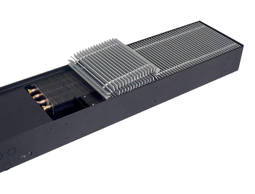
2 Overview Natural convection floor convectors TK-13 TK-13 Natural convection floor convectors principle of operation is natural air convection. They are designed for secondary room heating. Their heating capacities at catalogue conditions range up to 4 kw. They are distinguished for their silent operation. Forced convection floor convectors TKV-13 TKV-13 floor convectors principle of operation is forced convection. Natural air circulation is boosted by means of a fan. They are suitable for primary, in applications requiring higher heating capacities, also for secundary heating. Their heating capacities at catalogue conditions range up 12,8 kw. Usually the most appropriate models for installation are those with the housing height of 105 mm. In order to achieve higher heating capatities models with a housing height of 140 mm are available. Models with 80 mm housing height are designed for applications where installation height is lower than 100 mm (for example, renovation of old buildings). TK-13 TKV-13 Floor convectors for humid conditions with forced or natural convection TKV-S-13, TK-S-13 TKV-S-13 and TK-S-13 Floor convectors operate in the same way as the types TKV-13 and TK-13. They are particularly suitable for heating of areas with increased level of humidity such as swimming pools or similar. For safety, a low voltage fan (12 V) is installed in the TKV-S-13 model. Because of the potential ingress of water into the interior of the housing, a collection tray is mounted to collect and drain water. The technical characteristics are the same as the catalogue technical characteristics of the TK-13 and TKV-13 floor convectors of 105 mm height. TKV-S-13, TK-S-13 Cooling and heating floor convectors TKH-13 In summer, the TKH-13 floor convector draws in warm air from the areas around windows or hot walls, cools it in the heat exchanger, and feeds it back into the room. This reduces heat gains due to heat room envelope surfaces. In the cooling process, a part of moisture is extracted from the air; this dehumidification also contributes to thermal comfort.in winter, the TKH-13 floor convector is applied for heating like any other floor convector: it heats cold air from the window area and returns it into the room. Software Klima TK TKH-13 The package allows the selection of a standard heating floor convector (TK-13, TKV-13, TKH-13) either according to the available space for intsallation or a specified thermal capacity. Upon the entry of basic parameters the package lists the corresponding convector types, which we can correct or optimize as we want. Further we choose accessories (terad-on grille, control elements, ). Selection program evaluates the technical characteristics and prints the catalogue ordering key. The end result of selection can also be printed, as the basis for the order. 2
3 Content GENERAL 4 Natural convection floor convectors TK-13 6 Forced convection floor convectors TKV QUICK OVERVIEW OF FLOOR CONVECTORS TK-13 AND TKV Floor convectors FOR HUMID CONDITIONS WITH FORCED 40 OR NATURAL CONVECTION TKV-S-13, TK-S-13 cooling and heating floor convectors TKH EXAMPLES OF floor CONVECTOR connections INTO GROups 52 accessories 54 Types and colours of tread-on grilles 55 Control accessories - water side 56 Control accessories - air side 57 Other accessories 59 ORDERING KEY 61 Page 3


4 General General All measurements of floor convectors for heating and cooling are performed in conformance with European directives and European standards, which prescribes operation and usage of heating and cooling devices. Heating characteristics of floor convectors for heating (TK-13, TKV-13, TK-S-13, TKV-S-13) have been measured according to european standard EN 442, which precisely prescribes process of definition of nominal by temperature conditions 75 C, 65 C, 20 C. Laboratory for hat exchangers at Hidria Institute Klima with certified measurement equipment is the sixth suchlike in Europe for measurements of heating characteristics of heating devices and it has to provide repeatability and reparability. Heating and cooling characteristics of floor convectors for heating and cooling (TKH-13) have been measured according to EUROVENT standard 6/3 under the following conditions: 2-pipe systems: cooling 7 C / 12 C / 27 C / 47 % RH, heating 50 C / 20 C, water flow equal to water flow at cooling 4-pipe systems: cooling 7 C / 12 C / 27 C / 47 % RH, heating 70 C / 60 C / 20 C. Sound power level L WA (db), A weighted according to IEC and calculated in accordance with the recommendation of the EN ISO 3741 standard. Sound pressure level L pa (db), A weighted at certain distance in specific room can be calculated from sound power level data of device. 4


5 General Benefits In rooms with large glazing envelope surfaces or cold envelope walls, it is difficult to establish comfortable heating by means of conventional heating bodies only. Temperature differences between the glass surfaces and bulk air temperature lead to cooling of air in the boundary layer along the wall and in turn, to its downwards flow and spreading across the entire room floor area, the result being occupants discomfort. Especially when outside temperatures drop below 10 C, it is virtually impossible to maintain occupational comfort in rooms with large surface windows unless auxiliary floor convector heating is used. Floor convectors further prevent condensation build-up on glass, as they maintain a layer of warm humid air adjacent to the glass surfaces. Floor convectors (in particular the forced convection types) also prevent inlet of cold outside air. Functions Room heating (primary or secondary heating), Maintenance of uniform air circulation field in the room, and thereby, uniform distribution of heat throughout the room, Increasing of cold areas surface temperature, Prevention of condensation build-up on glass surfaces, Prevention of ingress of cold outside air through big glass surfaces, Room cooling (TKH-13 models), Heating of areas with increased humidity (TK-S-13, TKV-S-13). Characteristics High quality of material and production, High heating and cooling capacities, Good sound characteristics, Small water content in the heat exchanger and fast heating/cooling of the room, Installation into the floor, hence no occupation of the space, Installation in humid areas (TK-S-13 and TKV-S-13 models), Wide range of control accessories, Much flexibility to the needs of the project with specific versions (corner designs, rounded contours, variety of tread-on grilles), Easy installation, operation and maintenance. Pressure and temperature limitation of heat exchanger Maximal operating pressure: 11 bar. Maximal allowed pressure: 16 bar. Maximal water temperature: 110 C. Samples of heat exchangers have been tested by an accredited test laboratory. 5
.")

6 Natural convection floor convectors TK-13 Natural convection floor convectors TK-13 Application Natural convection floor convectors are applied basically as secondary heating bodies, in combination with other primary heating bodies (also in combination with TKV-13 s serving as primary heating bodies). They are installed to the floor, in the immediate proximity of windows, doors and other cooling surfaces. Recommended distance between floor convector and glass surface is mm. They are used for partial cover heat losses, prevention of condensation on glass surfaces, reduction of the convection effect from cold surfaces and prevention of inlet of cold outside air through doors. Floor convectors with natural convection feature silent operation. Operation Natural convection floor convectors apply the principle of natural circulation of air. Cold air enters into the floor convector, warms in the heat exchangers and rises into the room. warm air cold air TK-13 Components (Basic design) 1. Heat exchanger, 2. Tread-on grille, 3.. Types TK-13 floor convectors are available in 33 lengths TK-13 from 800 mm to 5000 mm, widths of 200 mm, 300 mm and 400 mm and heights of 70 mm, 105 mm and 140 mm. In the range up to 3000 mm lengths are available in the increments of 100 mm, over 3000 mm lengths are available in the increments of 200 mm. Control accessories The basic design has no water side control components. They have to be ordered as options to the basis version (for example: valves 01,,VP2). warm air cold air
7 Natural convection floor convectors TK-13 Technical data TK-13 Lx20x07 length L [mm] 75 C / 65 C / 20 C 70 C / 55 C / 20 C 55 C/ 45 C / 20 C Q h ṁ w Δp w Q h ṁ w Δp w Q h ṁ w Δp w [W] [kg/h] [kpa] [W] [kg/h] [kpa] [W] [kg/h] [kpa] ,8 < 0, ,9 < 0, ,4 < 0, ,8 < 0, ,8 < 0, ,2 < 0, ,7 < 0, ,8 < 0, ,0 < 0, ,7 < 0, ,8 < 0, ,9 < 0, ,6 < 0, ,7 < 0, ,7 < 0, ,6 < 0, ,7 < 0, ,5 < 0, ,5 < 0, ,7 < 0, ,4 < 0, ,5 0, ,6 < 0, ,2 < 0, ,5 0, ,6 < 0, ,1 < 0, ,4 0, ,6 < 0, ,9 < 0, ,4 0, ,5 < 0, ,7 < 0, ,3 0, ,5 < 0, ,6 < 0, ,3 0, ,5 < 0, ,4 < 0, ,2 0, ,4 < 0, ,3 < 0, ,2 0, ,4 0, ,1 < 0, ,1 0, ,4 0, ,9 < 0, ,1 0, ,4 0, ,8 0, ,0 0, ,3 0, ,6 0, ,0 0, ,3 0, ,5 0, ,0 0, ,3 0, ,3 0, ,9 0, ,2 0, ,1 0, ,9 0, ,2 0, ,0 0, ,8 0, ,2 0, ,8 0, ,7 0, ,1 0, ,5 0, ,6 0, ,0 0, ,2 0, ,5 0, ,0 0, ,8 0, ,5 0, ,9 0, ,5 0, ,4 0, ,8 0, ,2 0, ,3 0, ,8 0, ,9 0, ,2 0, ,7 0, ,5 0, ,1 0, ,6 0, ,2 0, ,0 0, ,6 0, ,9 0, ,9 0, ,5 0, ,6 0,06 Definition of symbols Q h [W] ṁ w [kg/h] Δp w [kpa] Water flow Pressure drop on the waterside 7
8 Natural convection floor convectors TK-13 TK-13 Lx30x07 length L [mm] 75 C / 65 C / 20 C 70 C / 55 C / 20 C 55 C/ 45 C / 20 C Q h ṁ w Δp w Q h ṁ w Δp w Q h ṁ w Δp w [W] [kg/h] [kpa] [W] [kg/h] [kpa] [W] [kg/h] [kpa] ,6 < 0, ,9 < 0, ,3 < 0, ,0 < 0, ,6 < 0, ,9 < 0, ,4 < 0, ,4 < 0, ,5 < 0, ,9 0, ,1 < 0, ,0 < 0, ,3 0, ,8 < 0, ,6 < 0, ,7 0, ,5 < 0, ,2 < 0, ,1 0, ,3 0, ,8 < 0, ,5 0, ,0 0, ,3 0, ,9 0, ,7 0, ,9 0, ,3 0, ,5 0, ,5 0, ,7 0, ,2 0, ,1 0, ,1 0, ,9 0, ,6 0, ,5 0, ,6 0, ,2 0, ,9 0, ,4 0, ,8 0, ,3 0, ,1 0, ,4 0, ,8 0, ,8 0, ,9 0, ,2 0, ,6 0, ,5 0, ,6 0, ,3 0, ,1 0, ,0 0, ,0 0, ,7 0, ,4 0, ,7 0, ,2 0, ,8 0, ,5 0, ,8 0, ,2 0, ,2 0, ,4 0, ,6 0, ,9 0, ,0 0, ,4 0, ,4 0, ,1 0, ,2 0, ,8 0, ,3 0, ,1 0, ,3 0, ,4 0, ,9 0, ,7 0, ,6 0, ,7 1, ,2 0, ,7 0, ,5 1, ,7 0, ,9 0, ,3 1, ,1 0, ,0 0, ,1 1, ,6 0, ,2 0, ,0 1, ,0 0, ,3 0, ,8 2, ,5 0, ,5 0,45 Definition of symbols Q h [W] ṁ w [kg/h] Δp w [kpa] Water flow Pressure drop on the waterside 8
9 Natural convection floor convectors TK-13 TK-13 Lx40x07 length L [mm] 75 C / 65 C / 20 C 70 C / 55 C / 20 C 55 C/ 45 C / 20 C Q h ṁ w Δp w Q h ṁ w Δp w Q h ṁ w Δp w [W] [kg/h] [kpa] [W] [kg/h] [kpa] [W] [kg/h] [kpa] ,5 <0, ,0 <0, ,3 <0, ,3 0, ,4 <0, ,6 <0, ,2 0, ,9 <0, ,9 <0, ,1 0, ,4 0, ,2 0, ,9 0, ,9 0, ,5 0, ,8 0, ,4 0, ,8 0, ,7 0, ,9 0, ,1 0, ,5 0, ,4 0, ,4 0, ,4 0, ,9 0, ,8 0, ,3 0, ,4 0, ,1 0, ,1 0, ,8 0, ,4 0, ,0 0, ,3 0, ,7 0, ,9 0, ,8 0, ,0 0, ,7 0, ,3 0, ,3 0, ,6 0, ,8 0, ,6 0, ,5 0, ,3 0, ,0 0, ,3 0, ,8 0, ,3 0, ,2 0, ,3 0, ,6 0, ,1 0, ,8 0, ,9 0, ,9 0, ,2 0, ,2 0, ,8 0, ,7 0, ,5 0, ,7 1, ,2 0, ,8 0, ,5 1, ,7 0, ,1 0, ,3 1, ,7 0, ,8 0, ,0 1, ,7 0, ,4 0, ,7 2, ,6 0, ,0 0, ,5 2, ,6 0, ,7 0, ,2 3, ,6 0, ,3 0, ,9 3, ,6 0, ,9 0, ,7 4, ,6 1, ,5 0, ,4 4, ,5 1, ,2 1, ,1 5, ,5 1, ,8 1, ,9 6, ,5 1, ,4 1,46 Definition of symbols Q h [W] ṁ w [kg/h] Δp w [kpa] Water flow Pressure drop on the waterside 9
10 Natural convection floor convectors TK-13 TK-13 Lx20x10 length L [mm] 75 C / 65 C / 20 C 70 C / 55 C / 20 C 55 C/ 45 C / 20 C Q h ṁ w Δp w Q h ṁ w Δp w Q h ṁ w Δp w [W] [kg/h] [kpa] [W] [kg/h] [kpa] [W] [kg/h] [kpa] ,4 < 0, ,3 < 0, ,8 < 0, ,0 < 0, ,6 < 0, ,0 < 0, ,6 < 0, ,9 < 0, ,2 < 0, ,2 < 0, ,2 < 0, ,4 < 0, ,8 < 0, ,6 < 0, ,6 < 0, ,4 < 0, ,9 < 0, ,8 < 0, ,0 0, ,2 < 0, ,0 < 0, ,6 0, ,5 < 0, ,2 < 0, ,2 0, ,8 < 0, ,4 < 0, ,8 0, ,1 < 0, ,6 < 0, ,4 0, ,5 < 0, ,8 < 0, ,0 0, ,8 0, ,0 < 0, ,6 0, ,1 0, ,2 0, ,2 0, ,4 0, ,4 0, ,8 0, ,7 0, ,6 0, ,4 0, ,1 0, ,8 0, ,1 0, ,4 0, ,0 0, ,7 0, ,7 0, ,2 0, ,3 0, ,0 0, ,4 0, ,9 0, ,3 0, ,6 0, ,5 0, ,7 0, ,8 0, ,1 0, ,0 0, ,0 0, ,7 0, ,3 0, ,2 0, ,9 0, ,9 0, ,7 0, ,1 0, ,6 0, ,1 0, ,3 0, ,2 0, ,5 0, ,5 0, ,8 0, ,9 0, ,7 0, ,5 0, ,3 0, ,9 0, ,1 0, ,7 0, ,1 0, ,8 0, ,1 0, ,3 0, ,4 0, ,5 0, ,5 0, ,0 0, ,9 0, ,7 0, ,7 0, ,3 0,13 Definition of symbols Q h [W] ṁ w [kg/h] Δp w [kpa] Water flow Pressure drop on the waterside 10
11 Natural convection floor convectors TK-13 TK-13 Lx30x10 length L [mm] 75 C / 65 C / 20 C 70 C / 55 C / 20 C 55 C/ 45 C / 20 C Q h ṁ w Δp w Q h ṁ w Δp w Q h ṁ w Δp w [W] [kg/h] [kpa] [W] [kg/h] [kpa] [W] [kg/h] [kpa] ,4 <0, ,0 <0, ,6 <0, ,8 <0, ,3 <0, ,8 <0, ,1 0, ,5 <0, ,9 <0, ,5 0, ,8 <0, ,1 <0, ,9 0, ,0 0, ,2 <0, ,2 0, ,3 0, ,4 0, ,6 0, ,6 0, ,5 0, ,9 0, ,8 0, ,7 0, ,3 0, ,1 0, ,8 0, ,6 0, ,3 0, ,0 0, ,0 0, ,6 0, ,2 0, ,3 0, ,8 0, ,3 0, ,7 0, ,1 0, ,5 0, ,1 0, ,4 0, ,6 0, ,4 0, ,6 0, ,8 0, ,8 0, ,9 0, ,9 0, ,1 0, ,1 0, ,1 0, ,5 0, ,4 0, ,2 0, ,8 0, ,6 0, ,4 0, ,2 0, ,9 0, ,5 0, ,6 0, ,1 0, ,7 0, ,9 0, ,4 0, ,8 0, ,3 0, ,7 0, ,0 0, ,6 0, ,9 0, ,1 0, ,0 0, ,2 0, ,3 0, ,7 0, ,7 0, ,6 0, ,4 1, ,2 0, ,9 0, ,1 1, ,7 0, ,2 0, ,8 1, ,2 0, ,5 0, ,5 1, ,7 0, ,8 0, ,3 2, ,2 0, ,1 0, ,0 2, ,8 0, ,5 0, ,7 3, ,3 0, ,8 0, ,4 3, ,8 0, ,1 0,84 Definition of symbols Q h [W] ṁ w [kg/h] Δp w [kpa] Water flow Pressure drop on the waterside 11
12 Natural convection floor convectors TK-13 TK-13 Lx40x10 length L [mm] 75 C / 65 C / 20 C 70 C / 55 C / 20 C 55 C/ 45 C / 20 C Q h ṁ w Δp w Q h ṁ w Δp w Q h ṁ w Δp w [W] [kg/h] [kpa] [W] [kg/h] [kpa] [W] [kg/h] [kpa] ,3 0, ,2 < 0, ,8 < 0, ,1 0, ,2 < 0, ,8 < 0, ,0 0, ,3 0, ,7 0, ,8 0, ,3 0, ,7 0, ,6 0, ,3 0, ,6 0, ,5 0, ,4 0, ,6 0, ,3 0, ,4 0, ,6 0, ,1 0, ,5 0, ,5 0, ,9 0, ,5 0, ,5 0, ,8 0, ,6 0, ,4 0, ,6 0, ,6 0, ,4 0, ,4 0, ,7 0, ,3 0, ,3 0, ,7 0, ,3 0, ,1 0, ,7 0, ,3 0, ,9 0, ,8 0, ,2 0, ,8 0, ,8 0, ,2 0, ,6 0, ,9 0, ,1 0, ,4 0, ,9 0, ,1 0, ,2 1, ,0 0, ,0 0, ,1 1, ,0 0, ,0 0, ,9 1, ,0 0, ,9 0, ,7 1, ,1 0, ,9 0, ,6 1, ,1 0, ,9 0, ,2 2, ,2 0, ,8 0, ,9 2, ,3 0, ,7 0, ,5 3, ,4 0, ,6 0, ,2 3, ,5 1, ,5 0, ,8 4, ,6 1, ,4 1, ,5 5, ,6 1, ,3 1, ,2 6, ,7 1, ,2 1, ,8 7, ,8 1, ,2 1, ,5 8, ,9 2, ,1 2, ,1 9, ,0 2, ,0 2,38 Definition of symbols Q h [W] ṁ w [kg/h] Δp w [kpa] Water flow Pressure drop on the waterside 12
13 Natural convection floor convectors TK-13 TK-13 Lx20x14 length L [mm] 75 C / 65 C / 20 C 70 C / 55 C / 20 C 55 C/ 45 C / 20 C Q h ṁ w Δp w Q h ṁ w Δp w Q h ṁ w Δp w [W] [kg/h] [kpa] [W] [kg/h] [kpa] [W] [kg/h] [kpa] ,3 < 0, ,1 < 0, ,3 < 0, ,4 < 0, ,6 < 0, ,7 < 0, ,5 < 0, ,2 < 0, ,0 < 0, ,5 0, ,7 < 0, ,4 < 0, ,6 0, ,2 < 0, ,7 < 0, ,7 0, ,8 < 0, ,0 < 0, ,8 0, ,3 < 0, ,4 < 0, ,8 0, ,8 0, ,7 < 0, ,9 0, ,3 0, ,0 0, ,0 0, ,9 0, ,4 0, ,1 0, ,4 0, ,7 0, ,1 0, ,9 0, ,0 0, ,2 0, ,5 0, ,4 0, ,3 0, ,0 0, ,7 0, ,4 0, ,5 0, ,0 0, ,5 0, ,0 0, ,4 0, ,5 0, ,6 0, ,7 0, ,6 0, ,1 0, ,1 0, ,7 0, ,6 0, ,4 0, ,8 0, ,2 0, ,7 0, ,8 0, ,7 0, ,1 0, ,9 0, ,2 0, ,4 0, ,0 0, ,7 0, ,7 0, ,1 0, ,8 0, ,4 0, ,3 0, ,9 0, ,1 0, ,5 0, ,9 0, ,8 0, ,6 0, ,0 0, ,4 0, ,8 0, ,0 0, ,1 0, ,9 0, ,1 0, ,8 0, ,1 1, ,1 0, ,4 0, ,2 1, ,2 0, ,1 0, ,4 1, ,3 0, ,8 0, ,5 1, ,3 0, ,5 0,32 Definition of symbols Q h [W] ṁ w [kg/h] Δp w [kpa] Water flow Pressure drop on the waterside 13
14 Natural convection floor convectors TK-13 TK-13 Lx30x14 length L [mm] 75 C / 65 C / 20 C 70 C / 55 C / 20 C 55 C/ 45 C / 20 C Q h ṁ w Δp w Q h ṁ w Δp w Q h ṁ w Δp w [W] [kg/h] [kpa] [W] [kg/h] [kpa] [W] [kg/h] [kpa] ,1 < 0, ,2 < 0, ,4 < 0, ,1 < 0, ,8 < 0, ,7 < 0, ,1 < 0, ,3 < 0, ,1 < 0, ,1 0, ,9 < 0, ,4 < 0, ,1 0, ,4 < 0, ,8 < 0, ,2 0, ,0 < 0, ,1 < 0, ,2 0, ,5 0, ,5 < 0, ,2 0, ,1 0, ,8 0, ,2 0, ,6 0, ,1 0, ,2 0, ,2 0, ,5 0, ,3 0, ,7 0, ,8 0, ,3 0, ,3 0, ,2 0, ,3 0, ,8 0, ,5 0, ,3 0, ,4 0, ,9 0, ,3 0, ,0 0, ,2 0, ,4 0, ,5 0, ,6 0, ,4 0, ,1 0, ,9 0, ,4 0, ,6 0, ,3 0, ,4 0, ,2 0, ,6 0, ,4 0, ,7 0, ,9 0, ,4 0, ,3 0, ,3 0, ,5 0, ,8 0, ,6 0, ,5 0, ,4 0, ,0 0, ,5 0, ,5 0, ,7 0, ,6 0, ,6 0, ,4 0, ,6 0, ,7 0, ,1 0, ,6 0, ,8 0, ,7 0, ,7 0, ,9 0, ,4 0, ,7 1, ,0 0, ,1 0, ,7 1, ,1 0, ,8 0, ,8 1, ,2 0, ,5 0, ,8 1, ,3 0, ,2 0, ,9 1, ,4 0, ,9 0,42 Definition of symbols Q h [W] ṁ w [kg/h] Δp w [kpa] Water flow Pressure drop on the waterside 14
15 Natural convection floor convectors TK-13 TK-13 Lx40x14 length L [mm] 75 C / 65 C / 20 C 70 C / 55 C / 20 C 55 C/ 45 C / 20 C Q h ṁ w Δp w Q h ṁ w Δp w Q h ṁ w Δp w [W] [kg/h] [kpa] [W] [kg/h] [kpa] [W] [kg/h] [kpa] ,9 < 0, ,3 < 0, ,4 < 0, ,4 < 0, ,2 < 0, ,0 < 0, ,9 < 0, ,0 < 0, ,6 < 0, ,3 < 0, ,9 < 0, ,1 < 0, ,8 < 0, ,7 < 0, ,7 < 0, ,3 < 0, ,5 < 0, ,3 < 0, ,8 < 0, ,4 < 0, ,9 < 0, ,3 0, ,2 < 0, ,5 < 0, ,7 0, ,0 < 0, ,1 < 0, ,2 0, ,9 < 0, ,7 < 0, ,7 0, ,7 < 0, ,3 < 0, ,2 0, ,6 < 0, ,9 < 0, ,6 0, ,4 < 0, ,5 < 0, ,1 0, ,2 < 0, ,1 < 0, ,6 0, ,1 0, ,7 0, ,1 0, ,9 0, ,3 0, ,6 0, ,7 0, ,8 0, ,0 0, ,6 0, ,4 0, ,5 0, ,4 0, ,0 0, ,0 0, ,3 0, ,6 0, ,5 0, ,1 0, ,2 0, ,9 0, ,9 0, ,8 0, ,4 0, ,8 0, ,4 0, ,4 0, ,4 0, ,6 0, ,3 0, ,1 0, ,8 0, ,3 0, ,8 0, ,0 0, ,2 0, ,5 0, ,1 0, ,2 0, ,1 0, ,3 0, ,2 0, ,8 0, ,5 0, ,1 0, ,5 0, ,7 0, ,1 0, ,2 0, ,9 0, ,0 0, ,8 0, ,1 0, ,0 0, ,5 0, ,2 0,08 Definition of symbols Q h [W] ṁ w [kg/h] Δp w [kpa] Water flow Pressure drop on the waterside 15
16 Natural convection floor convectors TK-13 Dimensions TK-13 Lx20x L 200 L Inner 1/2 thread TK-13 Lx20x R L 200 L Inner 1/2 thread R Inner 3/4 thread Inner 1/2 thread TK-13 Lx20x14 R15 L 200 L L 200 L
17 L 200 L Floor convectors Natural convection floor convectors TK Inner 1/2 thread TK-13 Lx30x07 R L L 200 L L Inner 1/2 thread Inner 1/2 thread TK -13 Lx30x10 R L 200 LL LL L Inner 1/2 thread Inner 1/2 thread R R Inner 3/4 thread TK-13 Lx30x R L L 200 L L Inner 3/4 thread , Inner 1/2 thread 17
18 Inner 1/2 thread Floor convectors Natural convection floor convectors TK-13 Inner 1/2 thread TK-13 Lx40x07 R15 R L 200 L 400L L 200 L 400 L Inner 3/4 thread Inner 1/2 thread Inner 1/2 thread TK-13 Lx40x10 R R15 42 L 200 L 400 L 200 L Inner 3/4 thread , Inner 1/2 thread TK-13 Lx40x R15 L 200 L Inner 3/4 thread 18


19 Forced convection floor convectors TKV-13 Forced convection floor convectors TKV-13 Application Floor convectors with forced convection are particularly suitable for primary or secondary heating of rooms, where faster heating and large heating capacities are required. They are installed to the floor, in the immediate proximity of windows, doors and other cooling surfaces. Recommended distance between floor convector and glass surface is mm. They are used for partial cover heat losses, prevention of condensation on glass surfaces, reduction of the convection effect from cold surfaces and prevention of inlet of cold outside air through doors. Floor convectors with forced convection feature low noise level during low fan speeds. Operation Forced convection floor convectors apply the principle of forced air circulation, maintained both by means of a tangential fan and by natural convection. Cold air enters into the floor convector, warms in the heat exchanger and rises into the room. Increased volume flow rate contributes to uniform distribution of heat in the room and improved occupancy comfort. warm air cold air warm air cold air TKV-13 components (basic design) 1. Heat exchanger, 2. Tangential fan, 3. Tread-on grille, 4.. Types TKV-13 floor convectors are available in 32 lengths from 900 mm to 5000 mm, in the widths of 200 mm, 300 mm and 400 mm and hights of 80 mm, 105 mm and 140 mm. In the range up to 3000 mm lengths are available in the increments of 100 mm, over 3000 lengths are available in the increments of 200 mm. Control accessories Basic version does not include regulation elements on water and air side. For water side regulation, different types of valves are available, codes 01,,VP2. For 3-step speed control of AC fan as a basic accessory, the autotransformer should be selected and if necessary the relay interface. For stepless control of AC or EC fans, you can choose the appropriate regulator from the accessories available. Depending on the selected type of floor convector type and control, different types of thermostats are available
20 Forced convection floor convectors TKV-13 Technical data TKV-13 Lx20x08 length L [mm] Sound Sound power Fan speed 75 C /65 C / 20 C 70 C /55 C / 20 C 55 C / 45 C / 20 C pressure Q h ṁ w Δp w Q h ṁ w Δp w Q h ṁ w Δp w L WA L pa AC [W] [kg/h] [kpa] [W] [kg/h] [kpa] [W] [kg/h] [kpa] [db] [db] MAX ,0 0, ,0 <0, ,2 <0, MED ,7 0, ,7 <0, ,3 <0, MIN ,8 <0, ,4 <0, ,7 <0,01 <30 23 STOP 95 8,1 <0, ,2 <0, ,9 <0,01 MAX ,5 0, ,7 <0, ,7 <0, MED ,2 0, ,4 <0, ,9 <0, MIN ,4 0, ,2 <0, ,4 <0,01 <30 23 STOP 112 9,6 <0, ,0 <0, ,6 <0,01 MAX ,1 0, ,4 0, ,2 0, MED ,7 0, ,2 <0, ,5 <0, MIN ,9 0, ,9 <0, ,1 <0,01 <30 23 STOP ,2 <0, ,7 <0, ,4 <0,01 MAX ,0 0, ,4 0, ,0 0, MED ,4 0, ,8 0, ,1 0, MIN ,7 0, ,3 0, ,0 0, STOP ,2 <0, ,8 <0, ,3 <0,01 MAX ,5 0, ,2 0, ,7 0, MED ,9 0, ,6 0, ,9 0, MIN ,2 0, ,0 0, ,7 0, STOP ,7 <0, ,6 <0, ,1 <0,01 MAX ,0 0, ,9 0, ,3 0, MED ,4 0, ,4 0, ,5 0, MIN ,7 0, ,8 0, ,4 0, STOP ,3 <0, ,3 <0, ,8 <0,01 MAX ,6 0, ,7 0, ,9 0, MED ,9 0, ,1 0, ,2 0, MIN ,2 0, ,6 0, ,1 0, STOP ,8 <0, ,1 <0, ,5 <0,01 MAX ,1 0, ,4 0, ,4 0, MED ,4 0, ,9 0, ,8 0, MIN ,7 0, ,3 0, ,8 0, STOP ,3 <0, ,9 <0, ,3 <0,01 MAX ,0 0, ,4 0, ,2 0, MED ,1 0, ,5 0, ,4 0, MIN ,5 0, ,7 0, ,7 0, STOP ,3 0, ,9 <0, ,2 <0,01 MAX ,5 0, ,1 0, ,9 0, MED ,6 0, ,3 0, ,1 0, MIN ,0 0, ,4 0, ,4 0, STOP ,9 0, ,7 <0, ,0 <0,01 MAX ,1 0, ,9 0, ,5 0, MED ,1 0, ,1 0, ,8 0, MIN ,5 0, ,2 0, ,1 0, STOP ,4 0, ,5 <0, ,7 <0,01 MAX ,0 0, ,8 0, ,1 0, MED ,7 0, ,7 0, ,3 0, MIN ,3 0, ,5 0, ,9 0, STOP ,4 0, ,6 <0, ,7 <0,01 MAX ,5 0, ,6 0, ,8 0, MED ,2 0, ,5 0, ,0 0, MIN ,8 0, ,3 0, ,7 0, STOP ,9 0, ,3 <0, ,4 <0,01 MAX ,0 0, ,3 0, ,4 0, MED ,8 0, ,2 0, ,7 0, MIN ,3 0, ,1 0, ,4 0, STOP ,5 0, ,1 <0, ,1 <0,01 MAX ,6 0, ,1 0, ,1 0, MED ,3 0, ,0 0, ,4 0, MIN ,9 0, ,9 0, ,1 0, STOP ,0 0, ,9 <0, ,9 <0,01 MAX ,1 0, ,8 0, ,6 0, MED ,8 0, ,8 0, ,1 0, MIN ,4 0, ,6 0, ,8 0, STOP ,5 0, ,7 0, ,6 <0,01 MAX ,0 1, ,8 0, ,3 0, MED ,4 0, ,4 0, ,6 0, MIN ,1 0, ,9 0, ,6 0, STOP ,5 0, ,7 0, ,6 0,01 MAX ,6 1, ,5 0, ,0 0, MED ,9 0, ,1 0, ,3 0, MIN ,7 0, ,7 0, ,4 0, STOP ,1 0, ,5 0, ,3 0,01 MAX ,1 1, ,3 0, ,6 0, MED ,5 0, ,9 0, ,0 0, MIN ,2 0, ,5 0, ,1 0, STOP ,6 0, ,3 0, ,0 0,01 MAX ,0 1, ,2 0, ,1 0, MED ,1 1, ,5 0, ,4 0, MIN ,9 0, ,7 0, ,9 0, STOP ,6 0, ,3 0, ,0 0,01 MAX ,5 1, ,0 0, ,8 0, MED ,6 1, ,3 0, ,2 0, MIN ,5 0, ,5 0, ,6 0, STOP ,1 0, ,1 0, ,7 0,01 20
21 Forced convection floor convectors TKV-13 TKV-13 Lx20x08 length L [mm] Sound Sound power Fan speed 75 C /65 C / 20 C 70 C /55 C / 20 C 55 C / 45 C / 20 C pressure Q h ṁ w Δp w Q h ṁ w Δp w Q h ṁ w Δp w L WA L pa AC [W] [kg/h] [kpa] [W] [kg/h] [kpa] [W] [kg/h] [kpa] [db] [db] MAX ,1 1, ,8 0, ,5 0, MED ,1 1, ,1 0, ,9 0, MIN ,0 0, ,3 0, ,4 0, STOP ,7 0, ,9 0, ,5 0,01 MAX ,1 2, ,3 0, ,8 0, MED ,2 1, ,6 0, ,3 0, MIN ,0 0, ,9 0, ,8 0, STOP ,7 0, ,5 0, ,9 0,01 MAX ,1 2, ,8 0, ,0 0, MED ,2 1, ,1 0, ,6 0, MIN ,1 0, ,4 0, ,3 0, STOP ,7 0, ,0 0, ,4 0,02 MAX ,2 2, ,2 0, ,1 0, MED ,2 1, ,7 0, ,9 0, MIN ,1 0, ,0 0, ,7 0, STOP ,8 0, ,6 0, ,9 0,02 MAX ,1 4, ,2 1, ,5 1, MED ,5 2, ,9 0, ,0 0, MIN ,6 1, ,6 0, ,3 0, STOP ,9 0, ,7 0, ,8 0,02 MAX ,1 4, ,7 1, ,8 1, MED ,5 2, ,5 0, ,5 0, MIN ,7 1, ,1 0, ,8 0, STOP ,9 0, ,2 0, ,3 0,03 MAX ,1 5, ,2 1, ,1 1, MED ,6 3, ,0 0, ,8 0, MIN ,7 1, ,7 0, ,3 0, STOP ,0 0, ,8 0, ,7 0,03 MAX ,2 5, ,7 1, ,3 1, MED ,6 3, ,5 0, ,2 0, MIN ,8 2, ,3 0, ,7 0, STOP ,0 0, ,3 0, ,2 0,04 MAX ,2 5, ,1 1, ,4 1, MED ,6 3, ,0 1, ,5 1, MIN ,8 2, ,8 0, ,1 0, STOP ,0 0, ,9 0, ,7 0,04 MAX ,1 9, ,1 2, ,9 2, MED ,9 5, ,3 1, ,6 1, MIN ,3 3, ,4 0, ,8 0, STOP ,1 0, ,0 0, ,6 0,05 MAX ,1 9, ,6 2, ,2 3, MED ,9 5, ,8 1, ,0 1, MIN ,4 3, ,0 0, ,3 1, STOP ,2 0, ,6 0, ,1 0,06 Note: The level of sound pressure L pa is calculated based on the level of sound power L WA emitted by the noise source at a certain distance (1 m) and depends on the installation type (free space or next to a wall). Definition of symbols Q h [W] ṁ w [kg/h] Δp w [kpa] Water flow Pressure drop on the waterside 21
22 Forced convection floor convectors TKV-13 TKV-13 Lx30x08 length L [mm] Sound Sound Fan speed 75 C / 65 C / 20 C 70 C /55 C / 20 C 55 C / 45 C / 20 C power pressure Q h ṁ w Δp w Q h ṁ w Δp w Q h ṁ w Δp w L WA L pa AC [W] [kg/h] [kpa] [W] [kg/h] [kpa] [W] [kg/h] [kpa] [db] [db] MAX ,0 0, ,1 0, ,7 0, MED ,8 0, ,1 0, ,8 0, MIN ,2 0, ,4 <0, ,8 <0, STOP ,8 <0, ,5 <0, ,0 <0,01 MAX ,4 0, ,3 0, ,6 0, MED ,1 0, ,3 0, ,8 0, MIN ,6 0, ,6 0, ,8 0, STOP ,2 <0, ,7 <0, ,1 <0,01 MAX ,7 0, ,4 0, ,3 0, MED ,5 0, ,4 0, ,7 0, MIN ,9 0, ,8 0, ,8 0, STOP ,5 <0, ,9 <0, ,2 <0,01 MAX ,4 0, ,9 0, ,5 0, MED ,9 0, ,9 0, ,5 0, MIN ,8 0, ,4 0, ,3 0, STOP ,9 0, ,7 <0, ,8 <0,01 MAX ,7 0, ,1 0, ,5 0, MED ,2 0, ,1 0, ,6 0, MIN ,1 0, ,6 0, ,5 0, STOP ,3 0, ,9 <0, ,9 <0,01 MAX ,1 0, ,3 0, ,5 0, MED ,6 0, ,3 0, ,6 0, MIN ,5 0, ,8 0, ,6 0, STOP ,6 0, ,1 <0, ,0 <0,01 MAX ,4 0, ,4 0, ,3 0, MED ,9 0, ,4 0, ,6 0, MIN ,8 0, ,0 0, ,6 0, STOP ,0 0, ,2 <0, ,1 <0,01 MAX ,8 0, ,5 0, ,1 0, MED ,3 0, ,6 0, ,6 0, MIN ,1 0, ,2 0, ,7 0, STOP ,3 0, ,4 0, ,2 <0,01 MAX ,4 0, ,1 0, ,3 0, MED ,7 0, ,0 0, ,3 0, MIN ,0 0, ,8 0, ,1 0, STOP ,8 0, ,2 0, ,8 0,01 MAX ,8 0, ,3 0, ,3 0, MED ,0 0, ,2 0, ,4 0, MIN ,3 0, ,0 0, ,3 0, STOP ,1 0, ,4 0, ,9 0,01 MAX ,1 1, ,4 0, ,2 0, MED ,3 0, ,4 0, ,4 0, MIN ,7 0, ,2 0, ,4 0, STOP ,4 0, ,6 0, ,0 0,01 MAX ,8 1, ,9 0, ,0 0, MED ,8 1, ,8 0, ,9 0, MIN ,5 0, ,8 0, ,6 0, STOP ,9 0, ,3 0, ,7 0,01 MAX ,1 2, ,1 0, ,0 0, MED ,1 1, ,0 0, ,1 0, MIN ,9 0, ,0 0, ,8 0, STOP ,2 0, ,5 0, ,8 0,01 MAX ,4 2, ,3 0, ,1 0, MED ,4 1, ,2 0, ,2 0, MIN ,2 0, ,2 0, ,9 0, STOP ,6 0, ,7 0, ,9 0,02 MAX ,8 2, ,4 0, ,0 0, MED ,8 1, ,4 0, ,2 0, MIN ,6 0, ,4 0, ,0 0, STOP ,9 0, ,9 0, ,0 0,02 MAX ,1 2, ,6 0, ,0 0, MED ,1 1, ,5 0, ,3 0, MIN ,9 0, ,6 0, ,1 0, STOP ,3 0, ,1 0, ,1 0,02 MAX ,8 3, ,1 1, ,8 1, MED ,5 2, ,9 0, ,8 0, MIN ,8 1, ,2 0, ,4 0, STOP ,7 0, ,9 0, ,7 0,03 MAX ,1 4, ,2 1, ,8 1, MED ,9 2, ,1 0, ,9 0, MIN ,1 1, ,4 0, ,6 0, STOP ,0 0, ,1 0, ,8 0,03 MAX ,5 4, ,4 1, ,8 1, MED ,2 2, ,3 0, ,0 0, MIN ,5 1, ,6 0, ,7 0, STOP ,4 0, ,2 0, ,9 0,03 MAX ,1 6, ,8 1, ,4 2, MED ,6 3, ,6 1, ,4 1, MIN ,3 2, ,2 0, ,9 0, STOP ,8 0, ,0 0, ,5 0,04 MAX ,5 6, ,0 1, ,5 2, MED ,0 3, ,8 1, ,5 1, MIN ,7 2, ,4 0, ,1 0, STOP ,2 0, ,2 0, ,6 0,04 22
23 Forced convection floor convectors TKV-13 TKV-13 Lx30x08 length L [mm] Sound Sound Fan speed 75 C / 65 C / 20 C 70 C /55 C / 20 C 55 C / 45 C / 20 C power pressure Q h ṁ w Δp w Q h ṁ w Δp w Q h ṁ w Δp w L WA L pa AC [W] [kg/h] [kpa] [W] [kg/h] [kpa] [W] [kg/h] [kpa] [db] [db] MAX ,8 7, ,2 2, ,6 2, MED ,3 3, ,0 1, ,6 1, MIN ,0 2, ,6 0, ,2 0, STOP ,5 0, ,4 0, ,7 0,05 MAX ,5 7, ,6 2, ,6 2, MED ,0 4, ,4 1, ,8 1, MIN ,7 2, ,0 0, ,5 0, STOP ,2 0, ,8 0, ,9 0,06 MAX ,2 8, ,8 2, ,4 2, MED ,7 4, ,8 1, ,9 1, MIN ,4 2, ,4 0, ,7 0, STOP ,9 0, ,2 0, ,1 0,07 MAX ,9 9, ,1 2, ,2 2, MED ,4 5, ,1 1, ,9 1, MIN ,0 3, ,8 0, ,8 0, STOP ,6 0, ,5 0, ,3 0,09 MAX ,2 16, ,2 4, ,1 5, MED ,2 9, ,9 2, ,1 2, MIN ,8 5, ,0 1, ,6 1, STOP ,5 0, ,1 0, ,5 0,11 MAX ,9 17, ,5 5, ,1 5, MED ,9 9, ,3 2, ,3 2, MIN ,4 5, ,5 1, ,8 1, STOP ,1 0, ,4 0, ,7 0,13 MAX ,6 18, ,8 5, ,1 6, MED ,6 10, ,7 3, ,4 3, MIN ,1 6, ,9 1, ,1 1, STOP ,8 0, ,8 0, ,9 0,15 MAX ,3 20, ,1 5, ,9 6, MED ,3 11, ,0 3, ,5 3, MIN ,8 7, ,2 1, ,3 2, STOP ,5 0, ,2 0, ,1 0,17 MAX ,9 21, ,4 6, ,7 6, MED ,9 12, ,4 3, ,5 3, MIN ,5 7, ,6 2, ,4 2, STOP ,2 0, ,6 0, ,3 0,20 MAX ,3 33, ,5 9, ,7 10, MED ,8 18, ,2 5, ,8 5, MIN ,2 11, ,9 3, ,2 3, STOP ,1 1, ,1 0, ,5 0,24 MAX ,0 35, ,8 10, ,7 11, MED ,5 19, ,6 5, ,0 5, MIN ,9 11, ,3 3, ,4 3, STOP ,8 1, ,5 0, ,7 0,27 Note: The level of sound pressure L pa is calculated based on the level of sound power L WA emitted by the noise source at a certain distance (1 m) and depends on the installation type (free space or next to a wall). Other technical data for TKV-13 Lx20x08 and TKV-13 Lx30x08 length [mm] Fan designation (max. no. of fans) Water connectors dimensions [ ] Air flow [m³/h] Max. input power [W] Max. input current [A] / , / , / , / , / , / , / , / ,40 Definition of symbols Q h [W] ṁ w [kg/h] Δp w [kpa] Water flow Pressure drop on the waterside 23
24 Forced convection floor convectors TKV-13 TKV-13 Lx20x10 length L [mm] Sound Sound power Fan speed 75 C / 65 C / 20 C 70 C /55 C / 20 C 55 C / 45 C / 20 C pressure Q h ṁ w Δp w Q h ṁ w Δp w Q h ṁ w Δp w L WA L pa AC EC [W] [kg/h] [kpa] [W] [kg/h] [kpa] [W] [kg/h] [kpa] [db] [db] MAX 100% ,6 0, ,9 <0, ,4 <0, MED 70% ,9 0, ,0 <0, ,9 <0, MIN 50% ,1 0, ,6 <0, ,9 <0,01 < % ,8 <0, ,1 <0, ,0 <0,01 <30 <20 STOP 109 9,4 <0, ,8 <0, ,5 <0,01 MAX 100% ,2 0, ,7 <0, ,9 0, MED 70% ,5 0, ,8 <0, ,5 <0, MIN 50% ,7 0, ,4 <0, ,6 <0,01 < % ,4 <0, ,9 <0, ,8 <0,01 <30 <20 STOP ,0 <0, ,6 <0, ,2 <0,01 MAX 100% ,8 0, ,4 0, ,4 0, MED 70% ,1 0, ,5 <0, ,1 <0, MIN 50% ,3 0, ,2 <0, ,3 <0,01 < % ,0 <0, ,7 <0, ,5 <0,01 <30 <20 STOP ,5 <0, ,4 <0, ,0 <0,01 MAX 100% ,0 0, ,3 0, ,4 0, MED 70% ,7 0, ,4 0, ,3 0, MIN 50% ,1 0, ,6 0, ,4 0, % ,5 0, ,5 <0, ,5 <0,01 <30 21 STOP ,6 <0, ,0 <0, ,5 <0,01 MAX 100% ,6 0, ,0 0, ,1 0, MED 70% ,2 0, ,2 0, ,0 0, MIN 50% ,7 0, ,4 0, ,2 0, % ,1 0, ,3 <0, ,3 <0,01 <30 21 STOP ,2 <0, ,8 <0, ,2 <0,01 MAX 100% ,2 0, ,8 0, ,8 0, MED 70% ,8 0, ,0 0, ,7 0, MIN 50% ,3 0, ,2 0, ,9 0, % ,6 0, ,1 0, ,1 0,01 <30 21 STOP ,8 <0, ,6 <0, ,0 <0,01 MAX 100% ,8 0, ,6 0, ,3 0, MED 70% ,4 0, ,8 0, ,4 0, MIN 50% ,8 0, ,0 0, ,6 0, % ,2 0, ,9 0, ,8 0,01 <30 21 STOP ,3 <0, ,4 <0, ,7 <0,01 MAX 100% ,3 0, ,3 0, ,8 0, MED 70% ,0 0, ,5 0, ,0 0, MIN 50% ,4 0, ,8 0, ,3 0, % ,8 0, ,7 0, ,6 0,01 <30 21 STOP ,9 0, ,2 <0, ,5 <0,01 MAX 100% ,6 0, ,2 0, ,9 0, MED 70% ,6 0, ,4 0, ,2 0, MIN 50% ,2 0, ,3 0, ,3 0, % ,3 0, ,6 0, ,6 0,02 <30 22 STOP ,0 0, ,8 <0, ,9 <0,01 MAX 100% ,2 0, ,0 0, ,5 0, MED 70% ,2 0, ,2 0, ,9 0, MIN 50% ,8 0, ,1 0, ,1 0, % ,9 0, ,4 0, ,3 0,02 <30 22 STOP ,5 0, ,6 <0, ,7 <0,01 MAX 100% ,8 0, ,7 0, ,1 0, MED 70% ,7 0, ,0 0, ,6 0, MIN 50% ,4 0, ,9 0, ,8 0, % ,5 0, ,2 0, ,1 0,02 <30 22 STOP ,1 0, ,4 <0, ,4 <0,01 MAX 100% ,1 0, ,5 0, ,9 0, MED 70% ,3 0, ,8 0, ,6 0, MIN 50% ,2 0, ,2 0, ,7 0, % ,0 0, ,0 0, ,0 0, STOP ,2 0, ,0 <0, ,9 <0,01 MAX 100% ,6 0, ,3 0, ,6 0, MED 70% ,9 0, ,6 0, ,3 0, MIN 50% ,8 0, ,1 0, ,5 0, % ,6 0, ,8 0, ,8 0, STOP ,8 0, ,8 <0, ,7 <0,01 MAX 100% ,2 0, ,1 0, ,3 0, MED 70% ,5 0, ,4 0, ,1 0, MIN 50% ,4 0, ,9 0, ,3 0, % ,1 0, ,6 0, ,6 0, STOP ,3 0, ,6 0, ,4 <0,01 MAX 100% ,8 0, ,9 0, ,9 0, MED 70% ,1 0, ,2 0, ,8 0, MIN 50% ,9 0, ,7 0, ,0 0, % ,7 0, ,4 0, ,4 0, STOP ,9 0, ,4 0, ,2 0,01 MAX 100% ,4 0, ,6 0, ,5 0, MED 70% ,6 0, ,0 0, ,4 0, MIN 50% ,5 0, ,5 0, ,8 0, % ,3 0, ,3 0, ,1 0, STOP ,5 0, ,2 0, ,9 0,01 MAX 100% ,7 1, ,4 0, ,3 0, MED 70% ,2 0, ,8 0, ,5 0, MIN 50% ,3 0, ,9 0, ,7 0, % ,8 0, ,1 0, ,1 0, STOP ,6 0, ,8 0, ,4 0,01 24
25 Forced convection floor convectors TKV-13 TKV-13 Lx20x10 length L [mm] Sound Sound power Fan speed 75 C / 65 C / 20 C 70 C /55 C / 20 C 55 C / 45 C / 20 C pressure Q h ṁ w Δp w Q h ṁ w Δp w Q h ṁ w Δp w L WA L pa AC EC [W] [kg/h] [kpa] [W] [kg/h] [kpa] [W] [kg/h] [kpa] [db] [db] MAX 100% ,2 1, ,2 0, ,0 0, MED 70% ,8 0, ,6 0, ,2 0, MIN 50% ,9 0, ,7 0, ,5 0, % ,4 0, ,9 0, ,9 0, STOP ,1 0, ,6 0, ,1 0,01 MAX 100% ,8 1, ,0 0, ,7 0, MED 70% ,4 0, ,4 0, ,9 0, MIN 50% ,5 0, ,5 0, ,2 0, % ,0 0, ,7 0, ,6 0, STOP ,7 0, ,4 0, ,9 0,01 MAX 100% ,1 1, ,7 0, ,3 0, MED 70% ,0 1, ,1 0, ,8 0, MIN 50% ,3 0, ,9 0, ,1 0, % ,5 0, ,5 0, ,5 0, STOP ,8 0, ,0 0, ,4 0,01 MAX 100% ,7 2, ,5 0, ,0 0, MED 70% ,6 1, ,9 0, ,6 0, MIN 50% ,9 0, ,7 0, ,9 0, % ,0 0, ,3 0, ,3 0, STOP ,4 0, ,8 0, ,1 0,01 MAX 100% ,3 2, ,3 0, ,7 0, MED 70% ,1 1, ,7 0, ,4 0, MIN 50% ,5 0, ,5 0, ,7 0, % ,6 0, ,1 0, ,1 0, STOP ,9 0, ,6 0, ,9 0,01 MAX 100% ,4 2, ,9 0, ,0 0, MED 70% ,3 1, ,3 0, ,8 0, MIN 50% ,6 0, ,1 0, ,2 0, % ,8 0, ,8 0, ,7 0, STOP ,1 0, ,2 0, ,4 0,02 MAX 100% ,6 2, ,4 0, ,2 0, MED 70% ,5 1, ,9 0, ,2 0, MIN 50% ,8 1, ,7 0, ,7 0, % ,9 0, ,4 0, ,2 0, STOP ,2 0, ,8 0, ,9 0,02 MAX 100% ,7 2, ,9 0, ,4 0, MED 70% ,6 1, ,5 0, ,5 0, MIN 50% ,9 1, ,3 0, ,1 0, % ,1 0, ,0 0, ,7 0, STOP ,4 0, ,4 0, ,4 0,02 MAX ,3 4, ,6 1, ,2 1, MED ,8 2, ,1 0, ,6 0, MIN ,6 1, ,1 0, ,1 0, STOP ,5 0, ,6 0, ,3 0,03 MAX ,4 5, ,2 1, ,5 1, MED ,0 3, ,7 0, ,1 1, MIN ,7 2, ,8 0, ,6 0, STOP ,7 0, ,2 0, ,8 0,04 MAX ,6 5, ,7 1, ,8 1, MED ,1 3, ,3 0, ,5 1, MIN ,9 2, ,4 0, ,1 0, STOP ,8 0, ,8 0, ,3 0,04 MAX ,8 5, ,2 1, ,0 1, MED ,3 3, ,9 1, ,9 1, MIN ,0 2, ,0 0, ,5 0, STOP ,0 0, ,4 0, ,8 0,05 MAX ,9 6, ,8 1, ,1 2, MED ,4 3, ,5 1, ,2 1, MIN ,2 2, ,6 0, ,0 0, STOP ,2 0, ,0 0, ,3 0,06 MAX ,5 9, ,4 2, ,0 3, MED ,6 5, ,1 1, ,4 1, MIN ,8 3, ,4 1, ,0 1, STOP ,3 0, ,2 0, ,3 0,07 MAX ,6 10, ,0 3, ,3 3, MED ,8 6, ,7 1, ,9 2, MIN ,0 4, ,0 1, ,5 1, STOP ,4 0, ,8 0, ,8 0,08 Note: The level of sound pressure L pa is calculated based on the level of sound power L WA emitted by the noise source at a certain distance (1 m) and depends on the installation type (free space or next to a wall). Definition of symbols Q h [W] ṁ w [kg/h] Δp w [kpa] Water flow Pressure drop on the waterside 25
26 Forced convection floor convectors TKV-13 TKV-13 Lx30x10 length L [mm] Sound Sound power Fan speed 75 C / 65 C / 20 C 70 C /55 C / 20 C 55 C / 45 C / 20 C pressure Q h ṁ w Δp w Q h ṁ w Δp w Q h ṁ w Δp w L WA L pa AC EC [W] [kg/h] [kpa] [W] [kg/h] [kpa] [W] [kg/h] [kpa] [db] [db] MAX 100% ,8 0, ,6 0, ,7 0, MED 70% ,6 0, ,4 0, ,1 0, MIN 50% ,7 0, ,4 0, ,0 0,01 < % ,0 0, ,7 <0, ,0 <0,01 <30 <20 STOP ,8 <0, ,5 <0, ,9 <0,01 MAX 100% ,5 0, ,9 0, ,6 0, MED 70% ,4 0, ,7 0, ,2 0, MIN 50% ,4 0, ,8 0, ,2 0,01 < % ,8 0, ,1 <0, ,3 <0,01 <30 <20 STOP ,5 <0, ,9 <0, ,2 <0,01 MAX 100% ,3 0, ,2 0, ,5 0, MED 70% ,1 0, ,1 0, ,3 0, MIN 50% ,2 0, ,2 0, ,3 0,01 < % ,5 0, ,4 0, ,6 0,01 <30 <20 STOP ,3 0, ,3 <0, ,4 <0,01 MAX 100% ,1 0, ,5 0, ,1 0, MED 70% ,8 0, ,9 0, ,7 0, MIN 50% ,8 0, ,0 0, ,3 0,03 < % ,6 0, ,4 0, ,3 0,02 <30 <20 STOP ,0 0, ,2 <0, ,2 <0,01 MAX 100% ,8 0, ,9 0, ,4 0, MED 70% ,5 0, ,4 0, ,0 0, MIN 50% ,6 0, ,4 0, ,6 0,04 < % ,3 0, ,9 0, ,7 0,02 <30 <20 STOP ,8 0, ,6 <0, ,5 <0,01 MAX 100% ,6 0, ,3 0, ,4 0, MED 70% ,3 0, ,7 0, ,2 0, MIN 50% ,3 0, ,8 0, ,9 0,05 < % ,1 0, ,3 0, ,1 0,03 <30 <20 STOP ,5 0, ,0 <0, ,8 <0,01 MAX 100% ,3 0, ,6 0, ,4 0, MED 70% ,0 0, ,1 0, ,3 0, MIN 50% ,1 0, ,2 0, ,1 0,06 < % ,8 0, ,7 0, ,4 0,03 <30 <20 STOP ,3 0, ,4 0, ,0 <0,01 MAX 100% ,1 0, ,9 0, ,3 0, MED 70% ,8 0, ,4 0, ,4 0, MIN 50% ,8 0, ,6 0, ,3 0,06 < % ,6 0, ,1 0, ,6 0,03 <30 <20 STOP ,0 0, ,8 0, ,3 0,01 MAX 100% ,9 1, ,2 0, ,9 0, MED 70% ,4 0, ,3 0, ,8 0, MIN 50% ,5 0, ,4 0, ,3 0, % ,6 0, ,1 0, ,4 0,07 <30 21 STOP ,8 0, ,7 0, ,1 0,01 MAX 100% ,6 1, ,6 0, ,1 0, MED 70% ,2 0, ,7 0, ,1 0, MIN 50% ,2 0, ,8 0, ,6 0, % ,3 0, ,5 0, ,7 0,07 <30 21 STOP ,5 0, ,1 0, ,4 0,01 MAX 100% ,4 1, ,9 0, ,1 0, MED 70% ,9 0, ,1 0, ,3 0, MIN 50% ,0 0, ,2 0, ,9 0, % ,1 0, ,0 0, ,1 0,08 <30 20 STOP ,3 0, ,5 0, ,6 0,01 MAX 100% ,2 2, ,1 0, ,3 0, MED 70% ,6 1, ,9 0, ,3 0, MIN 50% ,6 0, ,0 0, ,5 0, % ,1 0, ,9 0, ,6 0,13 <30 22 STOP ,0 0, ,4 0, ,4 0,02 MAX 100% ,9 3, ,5 0, ,5 0, MED 70% ,3 1, ,3 0, ,6 0, MIN 50% ,4 0, ,4 0, ,9 0, % ,9 0, ,3 0, ,0 0,15 <30 21 STOP ,8 0, ,8 0, ,7 0,02 MAX 100% ,7 3, ,9 0, ,7 1, MED 70% ,1 1, ,7 0, ,9 0, MIN 50% ,1 1, ,8 0, ,2 0, % ,6 0, ,8 0, ,4 0,16 <30 21 STOP ,5 0, ,2 0, ,9 0,02 MAX 100% ,4 3, ,2 1, ,8 1, MED 70% ,8 1, ,1 0, ,2 0, MIN 50% ,9 1, ,2 0, ,5 0, % ,4 0, ,2 0, ,8 0,18 <30 21 STOP ,3 0, ,6 0, ,2 0,02 MAX 100% ,2 3, ,5 1, ,8 1, MED 70% ,6 2, ,5 0, ,4 0, MIN 50% ,6 1, ,6 0, ,8 0, % ,1 0, ,6 0, ,1 0,20 <30 21 STOP ,0 0, ,0 0, ,5 0,03 MAX 100% ,0 5, ,8 1, ,1 1, MED 70% ,2 3, ,3 0, ,5 0, MIN 50% ,3 1, ,4 0, ,5 0, % ,1 0, ,6 0, ,7 0, STOP ,8 0, ,9 0, ,3 0,03 26
27 Forced convection floor convectors TKV-13 TKV-13 Lx30x10 length L [mm] Sound Sound power Fan speed 75 C / 65 C / 20 C 70 C /55 C / 20 C 55 C / 45 C / 20 C pressure Q h ṁ w Δp w Q h ṁ w Δp w Q h ṁ w Δp w L WA L pa AC EC [W] [kg/h] [kpa] [W] [kg/h] [kpa] [W] [kg/h] [kpa] [db] [db] MAX 100% ,7 6, ,1 1, ,3 2, MED 70% ,0 3, ,7 0, ,8 1, MIN 50% ,0 2, ,8 0, ,9 0, % ,9 1, ,0 0, ,1 0, STOP ,5 0, ,3 0, ,5 0,04 MAX 100% ,5 6, ,5 1, ,4 2, MED 70% ,7 3, ,1 1, ,0 1, MIN 50% ,8 2, ,3 0, ,2 0, % ,6 1, ,4 0, ,4 0, STOP ,3 0, ,7 0, ,8 0,04 MAX 100% ,3 9, ,6 2, ,4 3, MED 70% ,4 5, ,8 1, ,9 1, MIN 50% ,4 3, ,0 0, ,8 0, % ,7 1, ,3 0, ,9 0, STOP ,0 0, ,6 0, ,6 0,05 MAX 100% ,0 9, ,0 2, ,7 3, MED 70% ,1 5, ,3 1, ,3 1, MIN 50% ,2 3, ,4 0, ,2 0, % ,4 1, ,8 0, ,3 0, STOP ,8 0, ,0 0, ,9 0,06 MAX 100% ,8 10, ,4 3, ,9 3, MED 70% ,9 5, ,7 1, ,6 1, MIN 50% ,9 3, ,8 0, ,5 1, % ,2 1, ,2 0, ,7 0, STOP ,5 0, ,4 0, ,1 0,06 MAX 100% ,3 11, ,1 3, ,2 3, MED 70% ,4 6, ,5 1, ,1 1, MIN 50% ,4 3, ,7 1, ,2 1, % ,7 1, ,1 0, ,5 0, STOP ,0 0, ,2 0, ,7 0,08 MAX 100% ,8 12, ,8 3, ,3 4, MED 70% ,9 6, ,2 2, ,5 2, MIN 50% ,9 4, ,5 1, ,7 1, % ,2 2, ,9 0, ,1 0, STOP ,5 0, ,0 0, ,3 0,10 MAX 100% ,3 13, ,4 4, ,2 4, MED 70% ,4 7, ,9 2, ,9 2, MIN 50% ,4 4, ,2 1, ,2 1, % ,7 2, ,7 0, ,8 0, STOP ,0 0, ,8 0, ,8 0,12 MAX ,9 24, ,0 7, ,0 7, MED ,6 13, ,6 3, ,3 3, MIN ,7 7, ,8 2, ,8 2, STOP ,5 0, ,6 0, ,3 0,14 MAX ,4 25, ,7 7, ,4 8, MED ,1 14, ,4 4, ,8 4, MIN ,2 8, ,7 2, ,5 2, STOP ,0 0, ,4 0, ,9 0,17 MAX ,9 27, ,4 8, ,6 9, MED ,6 15, ,2 4, ,3 4, MIN ,7 9, ,5 2, ,1 2, STOP ,5 0, ,2 0, ,5 0,20 MAX ,4 29, ,1 8, ,7 9, MED ,1 16, ,9 4, ,7 4, MIN ,2 9, ,3 2, ,6 2, STOP ,0 1, ,0 0, ,0 0,23 MAX ,9 31, ,7 9, ,6 10, MED ,6 17, ,7 5, ,0 5, MIN ,7 10, ,1 3, ,1 3, STOP ,5 1, ,8 0, ,6 0,26 MAX ,4 48, ,3 14, ,6 15, MED ,9 26, ,4 7, ,5 8, MIN ,1 15, ,7 4, ,8 4, STOP ,0 1, ,6 0, ,1 0,31 MAX ,9 51, ,0 15, ,9 16, MED ,4 28, ,2 8, ,0 8, MIN ,6 17, ,5 4, ,4 5, STOP ,5 1, ,4 0, ,6 0,35 Note: The level of sound pressure L pa is calculated based on the level of sound power L WA emitted by the noise source at a certain distance (1 m) and depends on the installation type (free space or next to a wall). Definition of symbols Q h [W] ṁ w [kg/h] Δp w [kpa] Water flow Pressure drop on the waterside 27
28 Forced convection floor convectors TKV-13 TKV-13 Lx40x10 length L [mm] Sound Sound power Fan speed 75 C / 65 C / 20 C 70 C /55 C / 20 C 55 C / 45 C / 20 C pressure Q h ṁ w Δp w Q h ṁ w Δp w Q h ṁ w Δp w L WA L pa AC EC [W] [kg/h] [kpa] [W] [kg/h] [kpa] [W] [kg/h] [kpa] [db] [db] MAX 100% ,8 0, ,8 0, ,9 0, MED 70% ,1 0, ,1 0, ,0 0, MIN 50% ,3 0, ,6 0, ,1 0,02 < % ,1 0, ,4 0, ,6 0,01 <30 <20 STOP ,3 0, ,3 <0, ,3 <0,01 MAX 100% ,5 0, ,5 0, ,2 0, MED 70% ,8 0, ,0 0, ,6 0, MIN 50% ,0 0, ,5 0, ,7 0,02 < % ,8 0, ,3 0, ,4 0,01 <30 <20 STOP ,0 0, ,2 <0, ,0 <0,01 MAX 100% ,2 0, ,3 0, ,4 0, MED 70% ,5 0, ,8 0, ,0 0, MIN 50% ,7 0, ,3 0, ,3 0,03 < % ,5 0, ,2 0, ,0 0,01 <30 <20 STOP ,7 0, ,1 <0, ,7 <0,01 MAX 100% ,2 0, ,8 0, ,6 0, MED 70% ,7 0, ,5 0, ,6 0, MIN 50% ,1 0, ,4 0, ,6 0,08 < % ,7 0, ,0 0, ,6 0,04 <30 <20 STOP ,1 0, ,8 0, ,2 0,01 MAX 100% ,9 0, ,7 0, ,2 0, MED 70% ,4 0, ,4 0, ,4 0, MIN 50% ,9 0, ,3 0, ,5 0,10 < % ,4 0, ,9 0, ,5 0,05 <30 <20 STOP ,8 0, ,7 0, ,9 0,01 MAX 100% ,6 1, ,5 0, ,7 0, MED 70% ,1 0, ,3 0, ,0 0, MIN 50% ,6 0, ,2 0, ,2 0,12 < % ,1 0, ,8 0, ,3 0,06 <30 <20 STOP ,5 0, ,6 0, ,6 0,01 MAX 100% ,3 1, ,3 0, ,1 0, MED 70% ,9 0, ,1 0, ,6 0, MIN 50% ,3 0, ,1 0, ,9 0,14 < % ,8 0, ,7 0, ,0 0,08 <30 <20 STOP ,3 0, ,5 0, ,3 0,02 MAX 100% ,1 1, ,1 0, ,3 0, MED 70% ,6 0, ,9 0, ,1 0, MIN 50% ,0 0, ,9 0, ,5 0,16 < % ,5 0, ,6 0, ,7 0,09 <30 <20 STOP ,0 0, ,3 0, ,0 0,02 MAX 100% ,0 3, ,7 0, ,5 1, MED 70% ,8 1, ,7 0, ,7 0, MIN 50% ,4 1, ,0 0, ,8 0, % ,7 0, ,4 0, ,3 0,17 <30 21 STOP ,4 0, ,1 0, ,4 0,03 MAX 100% ,7 3, ,5 1, ,1 1, MED 70% ,5 1, ,5 0, ,4 0, MIN 50% ,1 1, ,9 0, ,6 0, % ,5 0, ,3 0, ,1 0,19 <30 21 STOP ,1 0, ,0 0, ,2 0,03 MAX 100% ,4 3, ,3 1, ,6 1, MED 70% ,2 2, ,4 0, ,1 0, MIN 50% ,8 1, ,8 0, ,3 0, % ,2 0, ,3 0, ,9 0,21 <30 21 STOP ,8 0, ,9 0, ,9 0,04 MAX 100% ,4 6, ,7 1, ,1 2, MED 70% ,4 3, ,0 1, ,2 1, MIN 50% ,3 2, ,8 0, ,3 0, % ,4 1, ,0 0, ,2 0,34 <30 22 STOP ,2 0, ,6 0, ,3 0,05 MAX 100% ,1 7, ,6 2, ,8 2, MED 70% ,1 4, ,9 1, ,0 1, MIN 50% ,0 2, ,7 0, ,1 0, % ,1 1, ,9 0, ,1 0,38 <30 22 STOP ,9 0, ,5 0, ,0 0,06 MAX 100% ,8 7, ,4 2, ,4 2, MED 70% ,9 4, ,8 1, ,8 1, MIN 50% ,7 2, ,6 0, ,9 0, % ,8 1, ,9 0, ,0 0,42 <30 22 STOP ,6 0, ,4 0, ,7 0,07 MAX 100% ,5 8, ,3 2, ,0 2, MED 70% ,6 4, ,7 1, ,4 1, MIN 50% ,4 2, ,5 0, ,7 0, % ,5 1, ,8 0, ,8 0,46 <30 21 STOP ,4 0, ,3 0, ,5 0,08 MAX 100% ,2 8, ,1 2, ,4 2, MED 70% ,3 5, ,5 1, ,1 1, MIN 50% ,1 3, ,4 0, ,4 0, % ,2 1, ,7 0, ,6 0,50 <30 21 STOP ,1 0, ,2 0, ,2 0,10 MAX 100% ,2 13, ,5 4, ,1 4, MED 70% ,5 7, ,2 2, ,3 2, MIN 50% ,5 4, ,4 1, ,5 1, % ,4 2, ,4 0, ,9 0, STOP ,5 0, ,9 0, ,6 0,12 MAX 100% ,9 14, ,4 4, ,8 4, MED 70% ,2 8, ,1 2, ,1 2, MIN 50% ,3 5, ,3 1, ,3 1, % ,1 2, ,3 0, ,8 0, STOP ,2 0, ,8 0, ,3 0,13 28
29 Forced convection floor convectors TKV-13 TKV-13 Lx40x10 length L [mm] Sound Sound power Fan speed 75 C / 65 C / 20 C 70 C /55 C / 20 C 55 C / 45 C / 20 C pressure Q h ṁ w Δp w Q h ṁ w Δp w Q h ṁ w Δp w L WA L pa AC EC [W] [kg/h] [kpa] [W] [kg/h] [kpa] [W] [kg/h] [kpa] [db] [db] MAX 100% ,6 15, ,2 4, ,3 4, MED 70% ,9 8, ,0 2, ,8 2, MIN 50% ,0 5, ,2 1, ,1 1, % ,8 2, ,3 0, ,6 0, STOP ,9 0, ,7 0, ,0 0,15 MAX 100% ,6 22, ,5 6, ,7 7, MED 70% ,1 12, ,5 3, ,8 3, MIN 50% ,4 7, ,2 2, ,9 2, % ,0 3, ,0 1, ,8 1, STOP ,3 0, ,4 0, ,5 0,18 MAX 100% ,3 23, ,4 6, ,4 7, MED 70% ,8 13, ,4 3, ,7 3, MIN 50% ,1 7, ,1 2, ,8 2, % ,8 4, ,9 1, ,7 1, STOP ,0 0, ,3 0, ,2 0,20 MAX 100% ,0 24, ,3 7, ,1 7, MED 70% ,6 13, ,3 3, ,4 4, MIN 50% ,8 8, ,0 2, ,6 2, % ,5 4, ,8 1, ,6 1, STOP ,8 1, ,2 0, ,9 0,22 MAX 100% ,4 27, ,0 7, ,2 8, MED 70% ,0 15, ,1 4, ,8 4, MIN 50% ,3 9, ,8 2, ,2 2, % ,9 5, ,7 1, ,3 1, STOP ,2 1, ,0 0, ,3 0,27 MAX 100% ,9 30, ,6 8, ,1 9, MED 70% ,4 17, ,8 4, ,1 5, MIN 50% ,7 10, ,6 3, ,6 3, % ,3 5, ,5 1, ,9 1, STOP ,6 1, ,7 0, ,8 0,32 MAX 100% ,3 32, ,2 9, ,8 10, MED 70% ,9 18, ,5 5, ,2 5, MIN 50% ,1 11, ,4 3, ,9 3, % ,8 6, ,3 1, ,4 1, STOP ,0 1, ,5 0, ,2 0,38 MAX ,2 57, ,2 16, ,7 18, MED ,3 31, ,8 9, ,1 9, MIN ,0 19, ,4 5, ,3 5, STOP ,9 2, ,0 0, ,0 0,49 MAX ,6 61, ,9 18, ,9 19, MED ,7 34, ,6 9, ,5 10, MIN ,4 21, ,3 6, ,9 6, STOP ,3 2, ,8 0, ,5 0,57 MAX ,0 66, ,5 19, ,9 20, MED ,1 37, ,4 10, ,9 11, MIN ,8 23, ,1 6, ,4 6, STOP ,7 3, ,5 0, ,9 0,66 MAX ,5 71, ,1 20, ,8 22, MED ,6 40, ,1 11, ,1 12, MIN ,2 25, ,8 7, ,8 7, STOP ,2 3, ,3 0, ,3 0,76 MAX ,9 76, ,7 22, ,6 23, MED ,0 43, ,8 12, ,3 12, MIN ,7 27, ,6 7, ,2 7, STOP ,6 4, ,1 1, ,8 0,86 MAX ,8 117, ,7 34, ,5 37, MED ,4 65, ,1 18, ,2 19, MIN ,5 40, ,7 11, ,6 11, STOP ,4 4, ,6 1, ,6 1,06 MAX ,2 124, ,4 36, ,6 39, MED ,8 69, ,9 19, ,6 20, MIN ,9 42, ,5 12, ,1 12, STOP ,8 5, ,3 1, ,1 1,19 Note: The level of sound pressure L pa is calculated based on the level of sound power L WA emitted by the noise source at a certain distance (1 m) and depends on the installation type (free space or next to a wall). Other technical data for TKV-13 Lx20x10, Lx30x10 and Lx40x10 length [mm] Fan designation (max. no. of fans) Water connectors dimensions [ ] Air flow [m³/h] Max. input power [W] Max. input current [A] / , / , / , / , / , / , / , / ,00 Definition of symbols Q h [W] ṁ w [kg/h] Water flow Δp w [kpa] Pressure drop on the waterside 29
30 Forced convection floor convectors TKV-13 TKV-13 Lx20x14 length L [mm] Sound Sound power Fan speed 75 C / 65 C / 20 C 70 C /55 C / 20 C 55 C / 45 C / 20 C pressure Q h ṁ w Δp w Q h ṁ w Δp w Q h ṁ w Δp w L WA L pa AC EC [W] [kg/h] [kpa] [W] [kg/h] [kpa] [W] [kg/h] [kpa] [db] [db] MAX 100% ,4 0, ,3 0, ,6 0, MED 70% ,7 0, ,0 0, ,5 0, MIN 50% ,0 0, ,4 <0, ,8 <0,01 < % ,3 0, ,9 <0, ,7 <0,01 <30 <20 STOP ,8 <0, ,5 <0, ,2 <0,01 MAX 100% ,2 0, ,2 0, ,3 0, MED 70% ,6 0, ,9 0, ,2 0, MIN 50% ,8 0, ,3 0, ,6 0,01 < % ,1 0, ,8 <0, ,6 <0,01 <30 <20 STOP ,7 <0, ,5 <0, ,0 <0,01 MAX 100% ,1 0, ,0 0, ,8 0, MED 70% ,4 0, ,8 0, ,8 0, MIN 50% ,7 0, ,2 0, ,4 0,01 < % ,0 0, ,8 <0, ,5 <0,01 <30 <20 STOP ,6 <0, ,5 <0, ,9 <0,01 MAX 100% ,0 0, ,8 0, ,8 0, MED 70% ,6 0, ,2 0, ,5 0, MIN 50% ,2 0, ,8 0, ,9 0, % ,8 0, ,9 0, ,7 0,01 <30 21 STOP ,0 0, ,2 <0, ,5 <0,01 MAX 100% ,9 0, ,7 0, ,6 0, MED 70% ,5 0, ,1 0, ,3 0, MIN 50% ,0 0, ,8 0, ,8 0, % ,7 0, ,8 0, ,6 0,01 <30 21 STOP ,8 0, ,1 <0, ,4 <0,01 MAX 100% ,8 0, ,6 0, ,3 0, MED 70% ,4 0, ,1 0, ,1 0, MIN 50% ,9 0, ,7 0, ,6 0, % ,5 0, ,8 0, ,5 0,02 <30 21 STOP ,7 0, ,1 <0, ,3 <0,01 MAX 100% ,6 0, ,5 0, ,9 0, MED 70% ,2 0, ,0 0, ,8 0, MIN 50% ,8 0, ,6 0, ,4 0, % ,4 0, ,7 0, ,4 0,02 <30 20 STOP ,6 0, ,0 <0, ,2 <0,01 MAX 100% ,5 0, ,4 0, ,5 0, MED 70% ,1 0, ,9 0, ,4 0, MIN 50% ,6 0, ,6 0, ,2 0, % ,3 0, ,7 0, ,2 0,02 <30 20 STOP ,4 0, ,0 <0, ,1 <0,01 MAX 100% ,4 1, ,2 0, ,5 0, MED 70% ,3 0, ,2 0, ,1 0, MIN 50% ,1 0, ,2 0, ,7 0, % ,1 0, ,8 0, ,4 0,04 <30 22 STOP ,8 0, ,7 0, ,7 <0,01 MAX 100% ,3 1, ,1 0, ,3 0, MED 70% ,2 0, ,2 0, ,9 0, MIN 50% ,0 0, ,1 0, ,6 0, % ,0 0, ,7 0, ,3 0,05 <30 22 STOP ,7 0, ,7 0, ,6 0,01 MAX 100% ,1 1, ,0 0, ,9 0, MED 70% ,1 0, ,1 0, ,6 0, MIN 50% ,9 0, ,1 0, ,4 0, % ,8 0, ,7 0, ,2 0,06 <30 22 STOP ,5 0, ,6 0, ,5 0,01 MAX 100% ,0 2, ,6 0, ,6 0, MED 70% ,3 1, ,4 0, ,9 0, MIN 50% ,4 0, ,6 0, ,7 0, % ,6 0, ,7 0, ,3 0, STOP ,9 0, ,4 0, ,1 0,01 MAX 100% ,9 2, ,6 0, ,4 0, MED 70% ,1 1, ,3 0, ,8 0, MIN 50% ,2 0, ,6 0, ,6 0, % ,5 0, ,7 0, ,2 0, STOP ,8 0, ,3 0, ,9 0,01 MAX 100% ,8 2, ,5 0, ,2 0, MED 70% ,0 1, ,3 0, ,6 0, MIN 50% ,1 0, ,5 0, ,5 0, % ,4 0, ,6 0, ,1 0, STOP ,6 0, ,3 0, ,8 0,01 MAX 100% ,6 2, ,4 0, ,9 0, MED 70% ,9 1, ,2 0, ,4 0, MIN 50% ,0 0, ,5 0, ,4 0, % ,2 0, ,6 0, ,0 0, STOP ,5 0, ,2 0, ,7 0,01 MAX 100% ,5 2, ,3 0, ,6 0, MED 70% ,7 1, ,1 0, ,1 0, MIN 50% ,8 0, ,4 0, ,2 0, % ,1 0, ,6 0, ,9 0, STOP ,4 0, ,2 0, ,6 0,02 MAX 100% ,4 4, ,0 1, ,3 1, MED 70% ,0 2, ,4 0, ,5 0, MIN 50% ,3 1, ,0 0, ,6 0, % ,9 0, ,6 0, ,1 0, STOP ,7 0, ,9 0, ,2 0,02 30
31 Forced convection floor convectors TKV-13 TKV-13 Lx20x14 length L [mm] Sound Sound power Fan speed 75 C / 65 C / 20 C 70 C /55 C / 20 C 55 C / 45 C / 20 C pressure Q h ṁ w Δp w Q h ṁ w Δp w Q h ṁ w Δp w L WA L pa AC EC [W] [kg/h] [kpa] [W] [kg/h] [kpa] [W] [kg/h] [kpa] [db] [db] MAX 100% ,3 4, ,9 1, ,1 1, MED 70% ,8 2, ,4 0, ,4 0, MIN 50% ,2 1, ,9 0, ,5 0, % ,8 0, ,6 0, ,0 0, STOP ,6 0, ,9 0, ,1 0,02 MAX 100% ,1 5, ,8 1, ,9 1, MED 70% ,7 2, ,3 0, ,2 0, MIN 50% ,0 1, ,9 0, ,3 0, % ,6 0, ,5 0, ,9 0, STOP ,5 0, ,8 0, ,0 0,02 MAX 100% ,1 7, ,4 2, ,4 2, MED 70% ,9 4, ,6 1, ,4 1, MIN 50% ,5 2, ,4 0, ,6 0, % ,4 1, ,6 0, ,9 0, STOP ,8 0, ,5 0, ,6 0,03 MAX 100% ,9 7, ,4 2, ,2 2, MED 70% ,8 4, ,5 1, ,3 1, MIN 50% ,4 2, ,4 0, ,5 0, % ,3 1, ,5 0, ,9 0, STOP ,7 0, ,5 0, ,5 0,03 MAX 100% ,8 8, ,3 2, ,0 2, MED 70% ,6 4, ,5 1, ,1 1, MIN 50% ,3 2, ,3 0, ,4 0, % ,2 1, ,5 0, ,8 0, STOP ,6 0, ,4 0, ,4 0,04 MAX 100% ,5 8, ,1 2, ,5 2, MED 70% ,4 4, ,3 1, ,7 1, MIN 50% ,0 2, ,2 0, ,1 0, % ,9 1, ,4 0, ,6 0, STOP ,3 0, ,4 0, ,1 0,04 MAX 100% ,3 9, ,9 2, ,9 3, MED 70% ,1 5, ,2 1, ,2 1, MIN 50% ,7 3, ,1 0, ,8 0, % ,6 1, ,3 0, ,4 0, STOP ,0 0, ,3 0, ,9 0,05 MAX 100% ,0 10, ,7 3, ,1 3, MED 70% ,8 5, ,0 1, ,6 1, MIN 50% ,5 3, ,0 1, ,5 1, % ,4 1, ,2 0, ,2 0, STOP ,8 0, ,2 0, ,7 0,06 MAX ,8 18, ,1 5, ,8 5, MED ,3 10, ,7 3, ,6 3, MIN ,4 6, ,1 1, ,2 1, STOP ,5 0, ,6 0, ,9 0,08 MAX ,5 20, ,0 5, ,4 6, MED ,0 11, ,6 3, ,2 3, MIN ,2 6, ,0 1, ,0 1, STOP ,3 0, ,5 0, ,7 0,10 MAX ,3 21, ,8 6, ,8 6, MED ,8 11, ,4 3, ,8 3, MIN ,9 7, ,9 2, ,7 2, STOP ,0 0, ,4 0, ,4 0,11 MAX ,0 23, ,6 6, ,2 7, MED ,5 12, ,2 3, ,3 4, MIN ,6 7, ,8 2, ,4 2, STOP ,7 0, ,3 0, ,2 0,13 MAX ,7 24, ,3 7, ,4 7, MED ,2 13, ,0 4, ,7 4, MIN ,4 8, ,7 2, ,1 2, STOP ,5 0, ,3 0, ,0 0,15 MAX ,6 38, ,8 11, ,2 12, MED ,7 21, ,8 6, ,7 6, MIN ,3 12, ,8 3, ,9 3, STOP ,2 0, ,7 0, ,2 0,18 MAX ,3 40, ,6 11, ,7 12, MED ,4 22, ,6 6, ,3 7, MIN ,1 13, ,8 3, ,6 3, STOP ,9 0, ,6 0, ,0 0,20 Note: The level of sound pressure L pa is calculated based on the level of sound power L WA emitted by the noise source at a certain distance (1 m) and depends on the installation type (free space or next to a wall). Definition of symbols Q h [W] ṁ w [kg/h] Δp w [kpa] Water flow Pressure drop on the waterside 31
32 Forced convection floor convectors TKV-13 TKV-13 Lx30x14 length L [mm] Sound Sound power Fan speed 75 C / 65 C / 20 C 70 C /55 C / 20 C 55 C / 45 C / 20 C pressure Q h ṁ w Δp w Q h ṁ w Δp w Q h ṁ w Δp w L WA L pa AC EC [W] [kg/h] [kpa] [W] [kg/h] [kpa] [W] [kg/h] [kpa] [db] [db] MAX 100% ,6 0, ,4 0, ,5 0, MED 70% ,0 0, ,4 0, ,5 0, MIN 50% ,9 0, ,1 <0, ,3 <0,01 < % ,3 0, ,2 <0, ,9 <0,01 <30 <20 STOP ,5 <0, ,9 <0, ,1 <0,01 MAX 100% ,8 0, ,9 0, ,6 0, MED 70% ,2 0, ,0 0, ,8 0, MIN 50% ,2 0, ,7 <0, ,8 <0,01 < % ,6 0, ,8 <0, ,5 <0,01 <30 <20 STOP ,8 <0, ,5 <0, ,6 <0,01 MAX 100% ,1 0, ,4 0, ,6 0, MED 70% ,5 0, ,6 0, ,0 0, MIN 50% ,4 0, ,4 0, ,1 0,01 < % ,9 0, ,5 <0, ,9 <0,01 <30 <20 STOP ,0 <0, ,2 <0, ,1 <0,01 MAX 100% ,6 0, ,6 0, ,2 0, MED 70% ,4 0, ,6 0, ,9 0, MIN 50% ,2 0, ,8 0, ,5 0, % ,1 0, ,0 0, ,7 0,01 <30 20 STOP ,5 0, ,4 <0, ,1 <0,01 MAX 100% ,9 0, ,2 0, ,6 0, MED 70% ,7 0, ,2 0, ,5 0, MIN 50% ,5 0, ,5 0, ,1 0, % ,4 0, ,7 0, ,3 0,01 <30 20 STOP ,7 0, ,1 <0, ,6 <0,01 MAX 100% ,2 0, ,8 0, ,9 0, MED 70% ,9 0, ,9 0, ,9 0, MIN 50% ,8 0, ,2 0, ,6 0, % ,7 0, ,4 0, ,9 0,01 <30 20 STOP ,0 0, ,7 <0, ,2 <0,01 MAX 100% ,4 0, ,3 0, ,1 0, MED 70% ,2 0, ,5 0, ,2 0, MIN 50% ,1 0, ,8 0, ,1 0, % ,0 0, ,0 0, ,4 0,02 <30 20 STOP ,3 0, ,4 <0, ,7 <0,01 MAX 100% ,7 0, ,9 0, ,1 0, MED 70% ,5 0, ,1 0, ,5 0, MIN 50% ,3 0, ,5 0, ,5 0, % ,2 0, ,7 0, ,9 0,02 <30 <20 STOP ,5 0, ,0 <0, ,2 <0,01 MAX 100% ,2 0, ,0 0, ,8 0, MED 70% ,4 0, ,0 0, ,5 0, MIN 50% ,1 0, ,9 0, ,9 0, % ,5 0, ,2 0, ,6 0,03 <30 22 STOP ,0 0, ,3 0, ,2 <0,01 MAX 100% ,5 0, ,6 0, ,1 0, MED 70% ,6 0, ,7 0, ,9 0, MIN 50% ,4 0, ,6 0, ,4 0, % ,8 0, ,9 0, ,2 0,04 <30 21 STOP ,2 0, ,9 0, ,7 0,01 MAX 100% ,7 0, ,2 0, ,4 0, MED 70% ,9 0, ,3 0, ,4 0, MIN 50% ,7 0, ,3 0, ,9 0, % ,0 0, ,5 0, ,8 0,04 <30 21 STOP ,5 0, ,6 0, ,2 0,01 MAX 100% ,2 1, ,1 0, ,4 0, MED 70% ,8 0, ,1 0, ,8 0, MIN 50% ,5 0, ,7 0, ,0 0, % ,3 0, ,0 0, ,4 0,07 <30 22 STOP ,9 0, ,9 0, ,3 0,01 MAX 100% ,5 1, ,8 0, ,9 0, MED 70% ,1 0, ,8 0, ,4 0, MIN 50% ,8 0, ,4 0, ,6 0, % ,6 0, ,7 0, ,0 0,08 <30 22 STOP ,2 0, ,5 0, ,8 0,01 MAX 100% ,8 1, ,4 0, ,3 0, MED 70% ,3 1, ,5 0, ,9 0, MIN 50% ,0 0, ,0 0, ,2 0, % ,8 0, ,4 0, ,6 0,08 <30 22 STOP ,5 0, ,2 0, ,3 0,01 MAX 100% ,0 1, ,0 0, ,6 0, MED 70% ,6 1, ,1 0, ,4 0, MIN 50% ,3 0, ,7 0, ,7 0, % ,1 0, ,0 0, ,2 0,09 <30 22 STOP ,7 0, ,8 0, ,8 0,01 MAX 100% ,3 2, ,6 0, ,8 0, MED 70% ,9 1, ,7 0, ,8 0, MIN 50% ,6 0, ,4 0, ,2 0, % ,4 0, ,7 0, ,7 0,10 <30 22 STOP ,0 0, ,5 0, ,3 0,02 MAX 100% ,8 3, ,6 0, ,0 1, MED 70% ,8 1, ,6 0, ,4 0, MIN 50% ,4 1, ,8 0, ,4 0, % ,6 0, ,2 0, ,3 0, STOP ,4 0, ,7 0, ,4 0,02 32
33 Forced convection floor convectors TKV-13 TKV-13 Lx30x14 length L [mm] Sound Sound power Fan speed 75 C / 65 C / 20 C 70 C /55 C / 20 C 55 C / 45 C / 20 C pressure Q h ṁ w Δp w Q h ṁ w Δp w Q h ṁ w Δp w L WA L pa AC EC [W] [kg/h] [kpa] [W] [kg/h] [kpa] [W] [kg/h] [kpa] [db] [db] MAX 100% ,1 3, ,2 1, ,4 1, MED 70% ,0 1, ,3 0, ,9 0, MIN 50% ,7 1, ,5 0, ,0 0, % ,9 0, ,8 0, ,9 0, STOP ,7 0, ,4 0, ,9 0,02 MAX 100% ,3 3, ,8 1, ,7 1, MED 70% ,3 2, ,9 0, ,4 0, MIN 50% ,9 1, ,1 0, ,5 0, % ,2 0, ,5 0, ,5 0, STOP ,0 0, ,0 0, ,4 0,03 MAX 100% ,8 5, ,7 1, ,6 1, MED 70% ,2 2, ,7 0, ,8 0, MIN 50% ,7 1, ,5 0, ,5 0, % ,4 0, ,9 0, ,0 0, STOP ,4 0, ,3 0, ,4 0,03 MAX 100% ,1 5, ,3 1, ,1 1, MED 70% ,5 3, ,4 0, ,4 0, MIN 50% ,0 1, ,2 0, ,1 0, % ,7 0, ,6 0, ,7 0, STOP ,7 0, ,9 0, ,9 0,03 MAX 100% ,4 5, ,0 1, ,5 1, MED 70% ,7 3, ,0 0, ,9 0, MIN 50% ,3 1, ,9 0, ,7 0, % ,0 0, ,3 0, ,3 0, STOP ,9 0, ,6 0, ,4 0,04 MAX 100% ,9 6, ,2 1, ,2 2, MED 70% ,3 3, ,4 1, ,9 1, MIN 50% ,8 2, ,2 0, ,8 0, % ,5 1, ,7 0, ,5 0, STOP ,5 0, ,9 0, ,4 0,05 MAX 100% ,4 7, ,4 2, ,7 2, MED 70% ,8 3, ,6 1, ,7 1, MIN 50% ,3 2, ,6 0, ,8 0, % ,0 1, ,1 0, ,6 0, STOP ,0 0, ,2 0, ,5 0,06 MAX 100% ,0 7, ,5 2, ,0 2, MED 70% ,3 4, ,8 1, ,4 1, MIN 50% ,9 2, ,8 0, ,8 0, % ,6 1, ,4 0, ,7 0, STOP ,6 0, ,5 0, ,5 0,07 MAX ,0 13, ,5 3, ,7 4, MED ,1 7, ,6 2, ,8 2, MIN ,5 4, ,7 1, ,2 1, STOP ,4 0, ,0 0, ,6 0,08 MAX ,5 14, ,8 4, ,5 4, MED ,7 7, ,9 2, ,9 2, MIN ,1 4, ,1 1, ,4 1, STOP ,9 0, ,3 0, ,6 0,10 MAX ,1 15, ,0 4, ,1 4, MED ,2 8, ,2 2, ,8 2, MIN ,6 5, ,4 1, ,4 1, STOP ,5 0, ,6 0, ,6 0,11 MAX ,6 16, ,2 4, ,6 5, MED ,7 9, ,5 2, ,6 2, MIN ,1 5, ,7 1, ,4 1, STOP ,0 0, ,9 0, ,6 0,13 MAX ,1 17, ,3 5, ,9 5, MED ,3 9, ,7 2, ,3 3, MIN ,7 6, ,0 1, ,4 1, STOP ,6 0, ,2 0, ,6 0,15 MAX ,1 27, ,4 8, ,8 8, MED ,1 14, ,5 4, ,8 4, MIN ,3 8, ,9 2, ,9 2, STOP ,4 0, ,7 0, ,7 0,18 MAX ,7 29, ,6 8, ,5 9, MED ,6 15, ,8 4, ,8 4, MIN ,8 9, ,3 2, ,0 2, STOP ,0 0, ,1 0, ,7 0,20 Note: The level of sound pressure L pa is calculated based on the level of sound power L WA emitted by the noise source at a certain distance (1 m) and depends on the installation type (free space or next to a wall). Definition of symbols Q h [W] ṁ w [kg/h] Δp w [kpa] Water flow Pressure drop on the waterside 33
34 Forced convection floor convectors TKV-13 TKV-13 Lx40x14 length L [mm] Sound Sound power Fan speed 75 C / 65 C / 20 C 70 C /55 C / 20 C 55 C / 45 C / 20 C pressure Q h ṁ w Δp w Q h ṁ w Δp w Q h ṁ w Δp w L WA L pa AC EC [W] [kg/h] [kpa] [W] [kg/h] [kpa] [W] [kg/h] [kpa] [db] [db] MAX 100% ,5 <0, ,1 <0, ,5 <0, MED 70% ,5 <0, ,6 <0, ,5 <0, MIN 50% ,2 <0, ,8 <0, ,2 <0,01 < % ,8 <0, ,8 <0, ,5 <0,01 <30 <20 STOP ,1 <0, ,6 <0, ,0 <0,01 MAX 100% ,3 0, ,4 <0, ,2 <0, MED 70% ,3 <0, ,0 <0, ,4 <0, MIN 50% ,0 <0, ,2 <0, ,3 <0,01 < % ,6 <0, ,2 <0, ,7 <0,01 <30 <20 STOP ,9 <0, ,0 <0, ,1 <0,01 MAX 100% ,1 0, ,6 <0, ,6 <0, MED 70% ,1 <0, ,3 <0, ,2 <0, MIN 50% ,8 <0, ,5 <0, ,3 <0,01 < % ,4 <0, ,6 <0, ,8 <0,01 <30 <20 STOP ,7 <0, ,4 <0, ,2 <0,01 MAX 100% ,5 0, ,5 0, ,1 0, MED 70% ,5 0, ,4 <0, ,6 <0, MIN 50% ,7 0, ,6 <0, ,0 <0, % ,0 <0, ,6 <0, ,5 <0,01 <30 20 STOP ,7 <0, ,3 <0, ,7 <0,01 MAX 100% ,3 0, ,9 0, ,2 0, MED 70% ,3 0, ,8 <0, ,9 <0, MIN 50% ,5 0, ,1 <0, ,3 <0, % ,8 0, ,1 <0, ,8 <0,01 <30 20 STOP ,5 <0, ,7 <0, ,9 <0,01 MAX 100% ,1 0, ,2 0, ,1 0, MED 70% ,1 0, ,2 0, ,9 0, MIN 50% ,3 0, ,5 <0, ,5 <0, % ,6 0, ,5 <0, ,0 <0,01 <30 20 STOP ,3 <0, ,1 <0, ,0 <0,01 MAX 100% ,9 0, ,5 0, ,8 0, MED 70% ,9 0, ,6 0, ,9 0, MIN 50% ,1 0, ,9 <0, ,6 <0, % ,4 0, ,9 <0, ,2 <0,01 <30 <20 STOP ,1 <0, ,5 <0, ,1 <0,01 MAX 100% ,7 0, ,8 0, ,3 0, MED 70% ,7 0, ,9 0, ,8 0, MIN 50% ,9 0, ,3 <0, ,6 <0, % ,2 0, ,3 <0, ,3 <0,01 <30 <20 STOP ,9 <0, ,9 <0, ,2 <0,01 MAX 100% ,0 0, ,7 0, ,8 0, MED 70% ,0 0, ,0 0, ,2 0, MIN 50% ,9 0, ,4 0, ,3 0, % ,8 0, ,4 <0, ,0 <0,01 <30 21 STOP ,8 <0, ,9 <0, ,7 <0,01 MAX 100% ,8 0, ,0 0, ,8 0, MED 70% ,8 0, ,4 0, ,3 0, MIN 50% ,7 0, ,9 0, ,5 0, % ,6 0, ,8 0, ,3 <0,01 <30 21 STOP ,6 0, ,3 <0, ,8 <0,01 MAX 100% ,6 0, ,4 0, ,6 0, MED 70% ,6 0, ,8 0, ,4 0, MIN 50% ,5 0, ,3 0, ,7 0, % ,4 0, ,2 0, ,5 0,01 <30 21 STOP ,4 0, ,7 <0, ,0 <0,01 MAX 100% ,9 0, ,0 0, ,2 0, MED 70% ,0 0, ,7 0, ,2 0, MIN 50% ,4 0, ,3 0, ,0 0, % ,0 0, ,2 0, ,0 0,01 <30 22 STOP ,4 0, ,6 <0, ,5 <0,01 MAX 100% ,7 0, ,4 0, ,4 0, MED 70% ,8 0, ,2 0, ,5 0, MIN 50% ,2 0, ,8 0, ,3 0, % ,8 0, ,7 0, ,3 0,01 <30 22 STOP ,2 0, ,0 <0, ,6 <0,01 MAX 100% ,5 0, ,8 0, ,5 0, MED 70% ,6 0, ,6 0, ,7 0, MIN 50% ,0 0, ,2 0, ,6 0, % ,6 0, ,1 0, ,6 0,01 <30 22 STOP ,0 0, ,4 <0, ,7 <0,01 MAX 100% ,3 0, ,2 0, ,4 0, MED 70% ,4 0, ,1 0, ,8 0, MIN 50% ,8 0, ,6 0, ,8 0, % ,4 0, ,6 0, ,8 0,01 <30 22 STOP ,8 0, ,8 <0, ,8 <0,01 MAX 100% ,1 0, ,5 0, ,2 0, MED 70% ,2 0, ,4 0, ,9 0, MIN 50% ,6 0, ,1 0, ,9 0, % ,2 0, ,0 0, ,0 0,01 <30 22 STOP ,6 0, ,2 <0, ,0 <0,01 MAX 100% ,4 0, ,2 0, ,0 0, MED 70% ,5 0, ,4 0, ,8 0, MIN 50% ,6 0, ,1 0, ,3 0, % ,8 0, ,0 0, ,6 0, STOP ,5 0, ,2 <0, ,5 <0,01 34
35 Forced convection floor convectors TKV-13 TKV-13 Lx40x14 length L [mm] Sound Sound power Fan speed 75 C / 65 C / 20 C 70 C /55 C / 20 C 55 C / 45 C / 20 C pressure Q h ṁ w Δp w Q h ṁ w Δp w Q h ṁ w Δp w L WA L pa AC EC [W] [kg/h] [kpa] [W] [kg/h] [kpa] [W] [kg/h] [kpa] [db] [db] MAX 100% ,2 0, ,6 0, ,1 0, MED 70% ,3 0, ,8 0, ,0 0, MIN 50% ,4 0, ,5 0, ,6 0, % ,6 0, ,4 0, ,8 0, STOP ,3 0, ,6 0, ,6 <0,01 MAX 100% ,0 0, ,0 0, ,0 0, MED 70% ,1 0, ,3 0, ,2 0, MIN 50% ,2 0, ,0 0, ,8 0, % ,4 0, ,9 0, ,1 0, STOP ,1 0, ,0 0, ,7 <0,01 MAX 100% ,4 0, ,5 0, ,3 0, MED 70% ,5 0, ,1 0, ,8 0, MIN 50% ,2 0, ,9 0, ,0 0, % ,0 0, ,8 0, ,5 0, STOP ,0 0, ,0 0, ,2 0,01 MAX 100% ,2 0, ,9 0, ,5 0, MED 70% ,3 0, ,6 0, ,1 0, MIN 50% ,0 0, ,4 0, ,3 0, % ,7 0, ,3 0, ,8 0, STOP ,8 0, ,4 0, ,3 0,01 MAX 100% ,0 0, ,4 0, ,7 0, MED 70% ,1 0, ,0 0, ,4 0, MIN 50% ,8 0, ,9 0, ,6 0, % ,5 0, ,7 0, ,1 0, STOP ,6 0, ,8 0, ,4 0,01 MAX 100% ,6 0, ,1 0, ,6 0, MED 70% ,7 0, ,9 0, ,7 0, MIN 50% ,4 0, ,7 0, ,1 0, % ,1 0, ,6 0, ,6 0, STOP ,2 0, ,6 0, ,7 0,01 MAX 100% ,2 0, ,7 0, ,3 0, MED 70% ,3 0, ,7 0, ,8 0, MIN 50% ,0 0, ,6 0, ,4 0, % ,7 0, ,5 0, ,0 0, STOP ,8 0, ,4 0, ,9 0,01 MAX 100% ,8 1, ,3 0, ,6 0, MED 70% ,9 0, ,4 0, ,8 0, MIN 50% ,6 0, ,4 0, ,6 0, % ,3 0, ,3 0, ,3 0, STOP ,4 0, ,1 0, ,2 0,01 MAX ,4 1, ,9 0, ,8 0, MED ,6 0, ,4 0, ,0 0, MIN ,5 0, ,5 0, ,6 0, STOP ,3 0, ,1 0, ,2 0,02 MAX ,0 1, ,6 0, ,9 0, MED ,2 1, ,3 0, ,4 0, MIN ,1 0, ,4 0, ,1 0, STOP ,9 0, ,9 0, ,4 0,02 MAX ,6 2, ,3 0, ,7 0, MED ,8 1, ,1 0, ,6 0, MIN ,7 0, ,3 0, ,5 0, STOP ,5 0, ,7 0, ,7 0,02 MAX ,2 2, ,0 0, ,3 0, MED ,4 1, ,9 0, ,7 0, MIN ,3 0, ,1 0, ,9 0, STOP ,1 0, ,5 0, ,9 0,02 MAX ,8 2, ,6 0, ,8 0, MED ,0 1, ,6 0, ,7 0, MIN ,9 0, ,9 0, ,1 0, STOP ,7 0, ,3 0, ,1 0,03 MAX ,5 3, ,2 1, ,1 1, MED ,7 1, ,7 0, ,1 0, MIN ,8 1, ,1 0, ,2 0, STOP ,6 0, ,2 0, ,2 0,03 MAX ,1 3, ,9 1, ,1 1, MED ,3 2, ,5 0, ,4 0, MIN ,4 1, ,0 0, ,6 0, STOP ,2 0, ,0 0, ,4 0,04 Note: The level of sound pressure L pa is calculated based on the level of sound power L WA emitted by the noise source at a certain distance (1 m) and depends on the installation type (free space or next to a wall). Other technical data for TKV-13 Lx20x14, Lx30x14 and Lx40x14 length [mm] Fan designation (max. no. of fans) Water connectors dimensions [ ] Air flow [m³/h] Max. input power [W] Max. input current [A] / , / , / , / , / , / , / , / ,00 Definition of symbols Q h [W] ṁ w [kg/h] Water flow Δp w [kpa] Pressure drop on the waterside 35
36 Forced convection floor convectors TKV-13 Dimensions TKV-13 Lx20x08 Inner 1/2 thread Inflow connector TKV-13 Lx20x10 Inner 1/2 thread Inflow connector TKV-13 Lx20x14 Inner 1/2 thread Inflow connector Inner 3/4 thread Inner 1/2 thread Inflow connector - above Inflow connector 36
37 Inner 1/2 thread Inflow connector Forced convection floor convectors TKV-13 TKV-13 Lx30x08 Inner 1/2 thread Inflow connector Inner 1/2 thread Inflow connector TKV-13 Lx30x10 Inner 3/4 thread Inner 1/2 thread Inflow connector - above Inflow connector TKV-13 Lx30x14 Inner 3/4 thread Inflow connector 37
38 Forced convection floor convectors TKV-13 Inner 1/2 thread Inflow connector Inner 3/4 thread Inflow connector - above TKV-13 Lx40x10 Inner 1/2 3/4 thread Inflow connector TKV-13 Lx40x14 Inner 3/4 thread Inflow connector 38
39 Quick overview of floor convectors TK-13 and TKV-13 Quick overview of floor convectors TK-13 and TKV-13 Basic characteristics Natural convection floor convectors TK-13 Forced convection floor convectors TKV-13 Heating capacities up to 4 kw do 12,8 kw (75 C/ 65 C / 20 C) Length mm mm up to 3000 mm increment 100 mm up to 3000 mm increment 100 mm over 3000 mm increment 200 mm over 3000 mm increment 200 mm Width 200, 300, 400 mm 200, 300, 400 mm Height 70, 105, 140 mm 80 (width 200 and 300 only), 105, 140 mm No. of fans Fan speed - MAX-MED-MIN-STOP (AC) or continuous (EC) Dimensions TK mm 300 mm 400 mm 70 mm 105 mm 140 mm Dimensions TKV mm 300 mm 400 mm 80 mm 105 mm 140 mm 39


40 Floor convectors for humid conditions with forced or natural convection TKV-S-13, TK-S-13 Floor convectors for humid conditions with forced or natural convection TKV-S-13, TK-S-13 Application TKV-S-13 and TK-S-13 floor convectors operate in the same way as the types TKV-13 and TK-13. They are particularly suitable for heating of areas with increased level of humidity such as swimming pools or similar. For safety, low voltage fan (12 V) is installed in the TKV-S-13 model. Setting up into the room and installation is the same as floor convectors TK-13 and TKV-13. They are used for prevention of condensation on glass surfaces, reduction of the convection effect from cold surfaces, and prevention of ingress of cold outside air. Because of the potential ingress of water into the interior of the housing, collection tray is mounted to collect and drain water, but we do not recommend installing floor conevctor directly at the pools, hot tubs,... (recommended distance> 1 m), or in a place with the greater possibility of ingress of water into the interior of the floor convector. Operation Operation is similar to the operation of TK- 13 and TKV-13 floor convectors. warm air cold air warm air cold air Important: Technical characteristics are the same as catalogue technical characteristics of TK-13 and TKV-13 floor convectors of 105 mm height. Component parts (basic design) 1. Heat exchanger, 2. Tangential fan 12 V (for TKV-S-13 only), 3. Electric connection socket (for TKV-S-13 only), 4. Tread-on grille, 5. Condensation collection drip tray, 6.. Types Floor convectors are available in 15 lengths from 1100 mm to 2500 mm, 200mm, 300 mm or 400 mm width and 140 mm height. Three level fan speed is available. Control accessories Water side regulation is possible with manual valves only. Two-way valve VP2-2C is not appropriate because of thermal actuator 230 V. Air supply side regulation (sets 09S) is defined separately, according to the order conditions
41 Floor convectors for humid conditions with forced or natural convection TKV-S-13, TK-S-13 Dimensions of connectors TK-S-13 Lx20x14 TKV-S-13 Lx20x TK-S-13 Lx30x14, Lx40x14 TKV-S-13 Lx30x14, Lx40x (126) 400 (300) R R15 R R15 R R R15 R R15 R (150) (150) A Basic requirements and information for ordering of TKV-S-13 regulation 400 (300) Up to 6 pieces 12 VAC ventilation fans can 30 be controlled with a single 09S regulation (126) unit. Three TKV-S x20x14/2/, R15 units, up to six TKV-S x20x14/1/ R15 units or any combination of these R9.5 with no more than six ventilation fans in all R15 R TKV-S-13 units can be connected this way. Correct cross section selection for cables, connecting 09S regulation units with each TKV-S-13 unit is an important factor in 25 the 55 electrical installation phase. The cable cross section depends on the total power 200 (150) 200 (150) of each TKV-S and the cable length - the distance between each TKV-S and 09S the regulation box. Regulation box 09S which must be placed out of humid place! A The following information must be specified upon ordering in order to select the correct 09S regulation box size and related wiring (connection between 09S and TKV-S-13): Number and type of floor convectors (TKV-S-13) the number of ventilation fans in each TKV-S-13, connected to a specific 09S regulation box is the most critical, Distance between electrical connection box of each TKV-S-13 and 09S regulation box (cable length), If more 09S regulation boxes are controlled using one T01 thermostat, this needs to be specified, which TKV-S-13 units are going to be connected to Examples each 09S regulation unit. Cross section of wires 2,5 mm 2 4 mm 2 6 mm Each TKV-S-13 must be connected to the 09S regulation box with its own cable. Parallel connection of more TKV-S-13 units with one cable is not allowed No. of ventilation fans max. length [m] max. length [m] max. length [m] 18.3 n= n=2 12, n=3 8,5 13,5 20 NOTE: Examples are valid for copper wiring only
42 Cooling and heating floor convectors TKH-13 Cooling and heating floor convectors TKH-13 Application Cooling and heating floor convectors are designed for secondary cooling in the period of cooling demand, in some cases for primary room cooling. Their operation is the most efficient, when they are installed close to the heat source (solar radiation through windows ), to prevent room temperature raising. They are suitable for all rooms with large hot envelope surfaces (large windows, glazing, etc., ). They are applied in buildings in which, due to the construction characteristics, ceiling cooling is not feasible. During the heating season, the convectors can be applied for room heating, similar way to TKV-13 type. Operation In the cooling mode, the TKH-13 floor convector draws in warm air from the areas around windows and hot walls, cools it in the heat exchanger, and feeds it back into the room. An insulated condensation collection tray is installed under the heat exchanger to collect and drain the condensate generated during the cooling of the air. In the heating mode, the process is inverted: the TKH draws in cold air from the window areas, heats it and feeds back into the room. TKH-13 components (basic design) 1. Heat exchanger, 2. Tangential fan, 3. Electric connection socket, 4. Tread-on grille, 5., 6. Condensation collection tray. Types Six TKH-13 models for 2-pipe systems and twelve TKH-13 models for 4-pipe systems are available. Control accessories The range of accessories equals to the one for TKV-13. Special designs of control accessories can be supplied on request. warm air cold air warm air cold air
43 Cooling and heating floor convectors TKH-13 Technical data TKH-13 Lx34x14/2C/45 Cooling length L [mm] Fan speed Temperature regime T w [ C] 7/12 8/14 14/18 AC EC T a [ C] Q c,t [W] MAX 100% Q c,s [W] ṁ w [kg/h] Δp w [kpa] 0,65 0,84 0,94 0,38 0,52 0,58 0,28 0,39 0,48 Q c,t [W] MED 70% Q c,s [W] ṁ w [kg/h] Δp w [kpa] 0,52 0,66 0,74 0,30 0,41 0,47 0,21 0,29 0,36 Q c,t [W] MIN 50% Q c,s [W] ṁ w [kg/h] Δp w [kpa] 0,35 0,45 0,50 0,21 0,28 0,32 0,14 0,20 0,24 Q c,t [W] MAX 100% Q c,s [W] ṁ w [kg/h] Δp w [kpa] 2,65 3,50 3,97 1,47 2,06 2,36 1,05 1,55 1,90 Q c,t [W] MED 70% Q c,s [W] ṁ w [kg/h] Δp w [kpa] 1,77 2,32 2,63 0,98 1,39 1,59 0,66 0,97 1,20 Q c,t [W] MIN 50% Q c,s [W] ṁ w [kg/h] Δp w [kpa] 1,39 1,81 2,04 0,77 1,10 1,24 0,49 0,72 0,91 Q c,t [W] MAX 100% Q c,s [W] ṁ w [kg/h] Δp w [kpa] 6,66 8,90 10,16 3,58 5,14 5,91 2,51 3,79 4,71 Q c,t [W] MED 70% Q c,s [W] ṁ w [kg/h] Δp w [kpa] 4,49 5,97 6,79 2,40 3,49 4,00 1,58 2,37 2,98 Q c,t [W] MIN 50% Q c,s [W] ṁ w [kg/h] Δp w [kpa] 3,93 5,21 5,92 2,09 3,06 3,50 1,32 1,98 2,52 Heating length L [mm] Fan speed Temperature regime T w [ C] 75/65 70/55 55/45 AC EC T a [ C] Q h [W] MAX 100% ṁ w [kg/h] Δp w [kpa] 1,01 0,39 0,43 Q h [W] MED 70% ṁ w [kg/h] Δp w [kpa] 0,54 0,22 0,24 Q h [W] MIN 50% ṁ w [kg/h] Δp w [kpa] 0,33 0,14 0,15 Q h [W] MAX 100% ṁ w [kg/h] Δp w [kpa] 4,66 1,65 1,82 Q h [W] MED 70% ṁ w [kg/h] Δp w [kpa] 2,33 0,87 0,95 Q h [W] MIN 50% ṁ w [kg/h] Δp w [kpa] 1,38 0,54 0,59 Q h [W] MAX 100% ṁ w [kg/h] Δp w [kpa] 12,57 4,25 4,72 Q h [W] MED 70% ṁ w [kg/h] Δp w [kpa] 6,13 2,17 2,39 Q h [W] MIN 50% ṁ w [kg/h] Δp w [kpa] 3,41 1,26 1,38 Definition of symbols AC AC 230 V fan EC DC 24 V fan, electronically commutated. Models with EC fans available on request only. Q c,t [W] Total cooling capacity at 50 % relative air humidity Q c,s [W] Sensible cooling capacity Q h [W] ṁ w [kg/h] Water flow Δp w [kpa] Pressure drop on the waterside T w [ C] Water temperature T a [ C] Air temperature 43
44 Cooling and heating floor convectors TKH-13 TKH-13 Lx34x14/2C/60 Cooling length L [mm] Fan speed Temperature regime T w [ C] 7/12 8/14 14/18 AC T a [ C] Q c,t [W] MAX Q c,s [W] ṁ w [kg/h] Δp w [kpa] 0,99 1,30 1,46 0,57 0,78 0,89 0,41 0,60 0,73 Q c,t [W] MED Q c,s [W] ṁ w [kg/h] Δp w [kpa] 0,88 1,15 1,29 0,50 0,70 0,79 0,34 0,49 0,61 Q c,t [W] MIN Q c,s [W] ṁ w [kg/h] MAX MED MIN MAX MED MIN Δp w [kpa] 0,64 0,82 0,92 0,36 0,51 0,57 0,23 0,34 0,42 Q c,t [W] Q c,s [W] ṁ w [kg/h] Δp w [kpa] 4,45 5,93 6,76 2,41 3,44 3,95 1,71 2,58 3,19 Q c,t [W] Q c,s [W] ṁ w [kg/h] Δp w [kpa] 3,58 4,77 5,43 1,92 2,78 3,19 1,27 1,91 2,40 Q c,t [W] Q c,s [W] ṁ w [kg/h] Δp w [kpa] 3,09 4,10 4,66 1,64 2,41 2,75 1,02 1,54 1,96 Q c,t [W] Q c,s [W] ṁ w [kg/h] Δp w [kpa] 9,08 12,19 13,95 4,81 6,97 8,04 3,31 5,06 6,32 Q c,t [W] Q c,s [W] ṁ w [kg/h] Δp w [kpa] 7,14 9,57 10,92 3,76 5,50 6,34 2,45 3,74 4,73 Q c,t [W] Q c,s [W] ṁ w [kg/h] Δp w [kpa] 5,44 7,24 8,25 2,84 4,21 4,83 1,75 2,67 3,42 Heating length L [mm] Fan speed Temperature regime T w [ C] 75/65 70/55 55/45 AC T a [ C] Q h [W] MAX ṁ w [kg/h] MED MIN MAX MED MIN MAX MED MIN Δp w [kpa] 1,85 0,68 0,75 Q h [W] ṁ w [kg/h] Δp w [kpa] 1,07 0,41 0,45 Q h [W] ṁ w [kg/h] Δp w [kpa] 0,72 0,29 0,31 Q h [W] ṁ w [kg/h] Δp w [kpa] 9,18 3,11 3,45 Q h [W] ṁ w [kg/h] Δp w [kpa] 4,98 1,75 1,94 Q h [W] ṁ w [kg/h] Δp w [kpa] 2,99 1,09 1,20 Q h [W] ṁ w [kg/h] Δp w [kpa] 25,84 8,42 9,40 Q h [W] ṁ w [kg/h] Δp w [kpa] 13,60 4,57 5,08 Q h [W] ṁ w [kg/h] Δp w [kpa] 9,80 3,36 3,72 Definition of symbols AC AC 230 V fan EC DC 24 V fan, electronically commutated. Models with EC fans available on request only. Q c,t [W] Total cooling capacity at 50 % relative air humidity Q c,s [W] Sensible cooling capacity Q h [W] ṁ w [kg/h] Water flow Δp w [kpa] Pressure drop on the waterside T w [ C] Water temperature T a [ C] Air temperature 44
45 Cooling and heating floor convectors TKH-13 TKH-13 Lx34x14/4C/45 Cooling length L [mm] Fan speed Temperature regime T w [ C] 7/12 8/14 14/18 AC EC T a [ C] Q c,t [W] MAX 100% Q c,s [W] ṁ w [kg/h] Δp w [kpa] 0,38 0,49 0,55 0,22 0,30 0,34 0,16 0,23 0,28 Q c,t [W] MED 70% Q c,s [W] ṁ w [kg/h] Δp w [kpa] 0,29 0,37 0,42 0,17 0,23 0,26 0,12 0,17 0,20 Q c,t [W] MIN 50% Q c,s [W] ṁ w [kg/h] Δp w [kpa] 0,19 0,24 0,27 0,11 0,15 0,17 0,08 0,11 0,13 Q c,t [W] MAX 100% Q c,s [W] ṁ w [kg/h] Δp w [kpa] 1,45 1,92 2,19 0,79 1,12 1,29 0,55 0,83 1,02 Q c,t [W] MED 70% Q c,s [W] ṁ w [kg/h] Δp w [kpa] 1,06 1,41 1,60 0,58 0,83 0,95 0,38 0,57 0,71 Q c,t [W] MIN 50% Q c,s [W] ṁ w [kg/h] Δp w [kpa] 0,74 0,97 1,09 0,40 0,58 0,66 0,26 0,38 0,48 Q c,t [W] MAX 100% Q c,s [W] ṁ w [kg/h] Δp w [kpa] 3,35 4,50 5,14 1,78 2,57 2,96 1,22 1,87 2,33 Q c,t [W] MED 70% Q c,s [W] ṁ w [kg/h] Δp w [kpa] 2,01 2,69 3,06 1,07 1,56 1,79 0,70 1,06 1,33 Q c,t [W] MIN 50% Q c,s [W] ṁ w [kg/h] Δp w [kpa] 1,55 2,06 2,34 0,82 1,21 1,38 0,51 0,77 0,98 Heating length L [mm] Fan speed Temperature regime T w [ C] 75/65 70/55 55/45 AC EC T a [ C] Q h [W] MAX 100% ṁ w [kg/h] Δp w [kpa] 0,93 0,36 0,40 Q h [W] MED 70% ṁ w [kg/h] Δp w [kpa] 0,52 0,22 0,24 Q h [W] MIN 50% ṁ w [kg/h] Δp w [kpa] 0,28 0,12 0,13 Q h [W] MAX 100% ṁ w [kg/h] Δp w [kpa] 5,80 2,05 2,26 Q h [W] MED 70% ṁ w [kg/h] Δp w [kpa] 2,63 0,99 1,08 Q h [W] MIN 50% ṁ w [kg/h] Δp w [kpa] 1,54 0,61 0,66 Q h [W] MAX 100% ṁ w [kg/h] Δp w [kpa] 19,49 6,53 7,26 Q h [W] MED 70% ṁ w [kg/h] Δp w [kpa] 7,49 2,66 2,94 Q h [W] MIN 50% ṁ w [kg/h] Δp w [kpa] 4,21 1,56 1,72 Definition of symbols AC AC 230 V fan EC DC 24 V fan, electronically commutated. Models with EC fans available on request only. Q c,t [W] Total cooling capacity at 50 % relative air humidity Q c,s [W] Sensible cooling capacity Q h [W] ṁ w [kg/h] Water flow Δp w [kpa] Pressure drop on the waterside T w [ C] Water temperature T a [ C] Air temperature 45
46 Cooling and heating floor convectors TKH-13 TKH-13 Lx40x14/4C/45 Cooling length L [mm] Fan speed Temperature regime T w [ C] 7/12 8/14 14/18 AC EC T a [ C] Q c,t [W] MAX 100% Q c,s [W] ṁ w [kg/h] Δp w [kpa] 0,54 0,70 0,79 0,31 0,42 0,48 0,22 0,32 0,39 Q c,t [W] MED 70% Q c,s [W] ṁ w [kg/h] Δp w [kpa] 0,41 0,53 0,60 0,23 0,33 0,37 0,16 0,23 0,28 Q c,t [W] MIN 50% Q c,s [W] ṁ w [kg/h] Δp w [kpa] 0,27 0,34 0,38 0,15 0,21 0,24 0,10 0,15 0,18 Q c,t [W] MAX 100% Q c,s [W] ṁ w [kg/h] Δp w [kpa] 2,15 2,86 3,27 1,16 1,66 1,91 0,80 1,21 1,51 Q c,t [W] MED 70% Q c,s [W] ṁ w [kg/h] Δp w [kpa] 1,54 2,04 2,33 0,83 1,20 1,37 0,54 0,82 1,02 Q c,t [W] MIN 50% Q c,s [W] ṁ w [kg/h] Δp w [kpa] 1,08 1,42 1,61 0,58 0,84 0,96 0,37 0,55 0,69 Q c,t [W] MAX 100% Q c,s [W] ṁ w [kg/h] Δp w [kpa] 4,63 6,23 7,13 2,44 3,55 4,10 1,67 2,57 3,21 Q c,t [W] MED 70% Q c,s [W] ṁ w [kg/h] Δp w [kpa] 2,73 3,65 4,17 1,45 2,11 2,43 0,95 1,44 1,82 Q c,t [W] MIN 50% Q c,s [W] ṁ w [kg/h] Δp w [kpa] 2,10 2,79 3,18 1,11 1,63 1,87 0,69 1,05 1,34 Heating length L [mm] Fan speed Temperature regime T w [ C] 75/65 70/55 55/45 AC EC T a [ C] Q h [W] MAX 100% ṁ w [kg/h] Δp w [kpa] 2,14 0,79 0,87 Q h [W] MED 70% ṁ w [kg/h] Δp w [kpa] 1,11 0,43 0,47 Q h [W] MIN 50% ṁ w [kg/h] Δp w [kpa] 0,62 0,25 0,28 Q h [W] MAX 100% ṁ w [kg/h] Δp w [kpa] 12,30 4,17 4,63 Q h [W] MED 70% ṁ w [kg/h] Δp w [kpa] 6,08 2,15 2,38 Q h [W] MIN 50% ṁ w [kg/h] Δp w [kpa] 3,51 1,30 1,43 Q h [W] MAX 100% ṁ w [kg/h] Δp w [kpa] 37,60 12,27 13,69 Q h [W] MED 70% ṁ w [kg/h] Δp w [kpa] 17,95 6,08 6,75 Q h [W] MIN 50% ṁ w [kg/h] Δp w [kpa] 9,78 3,44 3,80 Definition of symbols AC AC 230 V fan EC DC 24 V fan, electronically commutated. Models with EC fans available on request only. Q c,t [W] Total cooling capacity at 50 % relative air humidity Q c,s [W] Sensible cooling capacity Q h [W] ṁ w [kg/h] Water flow Δp w [kpa] Pressure drop on the waterside T w [ C] Water temperature T a [ C] Air temperature 46
47 Cooling and heating floor convectors TKH-13 TKH-13 Lx34x14/4C/60 Cooling length L [mm] Fan speed Temperature regime T w [ C] 7/12 8/14 14/18 AC T a [ C] Q c,t [W] MAX Q c,s [W] ṁ w [kg/h] Δp w [kpa] 0,64 0,85 0,96 0,36 0,51 0,58 0,26 0,38 0,46 Q c,t [W] MED Q c,s [W] ṁ w [kg/h] Δp w [kpa] 0,49 0,64 0,72 0,27 0,38 0,44 0,19 0,27 0,34 Q c,t [W] MIN Q c,s [W] ṁ w [kg/h] MAX MED MIN MAX MED MIN Δp w [kpa] 0,31 0,40 0,45 0,18 0,25 0,28 0,12 0,17 0,21 Q c,t [W] Q c,s [W] ṁ w [kg/h] Δp w [kpa] 2,49 3,34 3,82 1,33 1,92 2,21 0,92 1,39 1,74 Q c,t [W] Q c,s [W] ṁ w [kg/h] Δp w [kpa] 1,82 2,42 2,77 0,96 1,40 1,61 0,62 0,95 1,20 Q c,t [W] Q c,s [W] ṁ w [kg/h] Δp w [kpa] 1,24 1,64 1,87 0,66 0,96 1,10 0,41 0,62 0,79 Q c,t [W] Q c,s [W] ṁ w [kg/h] Δp w [kpa] 5,39 7,29 8,35 2,82 4,12 4,76 1,92 2,96 3,72 Q c,t [W] Q c,s [W] ṁ w [kg/h] Δp w [kpa] 3,20 4,30 4,92 1,67 2,46 2,84 1,07 1,65 2,09 Q c,t [W] Q c,s [W] ṁ w [kg/h] Δp w [kpa] 2,45 3,27 3,73 1,27 1,89 2,17 0,78 1,19 1,53 Heating length L [mm] Fan speed Temperature regime T w [ C] 75/65 70/55 55/45 AC T a [ C] Q h [W] MAX ṁ w [kg/h] MED MIN MAX MED MIN MAX MED MIN Δp w [kpa] 1,82 0,67 0,74 Q h [W] ṁ w [kg/h] Δp w [kpa] 1,00 0,39 0,43 Q h [W] ṁ w [kg/h] Δp w [kpa] 0,50 0,21 0,23 Q h [W] ṁ w [kg/h] Δp w [kpa] 12,31 4,14 4,60 Q h [W] ṁ w [kg/h] Δp w [kpa] 5,48 1,94 2,14 Q h [W] ṁ w [kg/h] Δp w [kpa] 3,12 1,15 1,27 Q h [W] ṁ w [kg/h] Δp w [kpa] 39,98 12,95 14,45 Q h [W] ṁ w [kg/h] Δp w [kpa] 16,19 5,47 6,08 Q h [W] ṁ w [kg/h] Δp w [kpa] 8,81 3,10 3,42 Definition of symbols AC AC 230 V fan EC DC 24 V fan, electronically commutated. Models with EC fans available on request only. Q c,t [W] Total cooling capacity at 50 % relative air humidity Q c,s [W] Sensible cooling capacity Q h [W] ṁ w [kg/h] Water flow Δp w [kpa] Pressure drop on the waterside T w [ C] Water temperature T a [ C] Air temperature 47
48 Cooling and heating floor convectors TKH-13 TKH-13 Lx40x14/4C/60 Cooling length L [mm] Fan speed Temperature regime T w [ C] 7/12 8/14 14/18 AC T a [ C] Q c,t [W] MAX Q c,s [W] ṁ w [kg/h] MED MIN MAX MED MIN MAX MED MIN Δp w [kpa] 0,92 1,22 1,38 0,51 0,72 0,82 0,36 0,54 0,66 Q c,t [W] Q c,s [W] ṁ w [kg/h] Δp w [kpa] 0,70 0,91 1,03 0,38 0,55 0,62 0,26 0,38 0,47 Q c,t [W] Q c,s [W] ṁ w [kg/h] Δp w [kpa] 0,44 0,57 0,65 0,25 0,35 0,40 0,16 0,24 0,29 Q c,t [W] Q c,s [W] ṁ w [kg/h] Δp w [kpa] 3,71 5,00 5,72 1,96 2,85 3,29 1,34 2,06 2,58 Q c,t [W] Q c,s [W] ṁ w [kg/h] Δp w [kpa] 2,64 3,54 4,04 1,38 2,03 2,34 0,89 1,36 1,73 Q c,t [W] Q c,s [W] ṁ w [kg/h] Δp w [kpa] 1,83 2,43 2,76 0,96 1,41 1,62 0,59 0,90 1,15 Q c,t [W] Q c,s [W] ṁ w [kg/h] Δp w [kpa] 7,49 10,13 11,63 3,89 5,70 6,61 2,64 4,09 5,15 Q c,t [W] Q c,s [W] ṁ w [kg/h] Δp w [kpa] 4,37 5,88 6,72 2,27 3,35 3,87 1,46 2,26 2,87 Q c,t [W] Q c,s [W] ṁ w [kg/h] Δp w [kpa] 3,33 4,46 5,09 1,72 2,56 2,95 1,05 1,62 2,09 Heating length L [mm] Fan speed Temperature regime T w [ C] 75/65 70/55 55/45 AC T a [ C] Q h [W] MAX ṁ w [kg/h] Δp w [kpa] 4,44 1,55 1,71 Q h [W] MED ṁ w [kg/h] Δp w [kpa] 2,23 0,82 0,90 Q h [W] MIN ṁ w [kg/h] MAX MED MIN MAX MED MIN Δp w [kpa] 1,20 0,46 0,51 Q h [W] ṁ w [kg/h] Δp w [kpa] 28,93 9,40 10,49 Q h [W] ṁ w [kg/h] Δp w [kpa] 13,96 4,70 5,22 Q h [W] ṁ w [kg/h] Δp w [kpa] 7,86 2,74 3,03 Q h [W] ṁ w [kg/h] Δp w [kpa] 84,33 26,72 29,91 Q h [W] ṁ w [kg/h] Δp w [kpa] 39,53 12,87 14,36 Q h [W] ṁ w [kg/h] Δp w [kpa] 21,11 7,08 7,88 Definition of symbols AC AC 230 V fan EC DC 24 V fan, electronically commutated. Models with EC fans available on request only. Q c,t [W] Total cooling capacity at 50 % relative air humidity Q c,s [W] Sensible cooling capacity Q h [W] ṁ w [kg/h] Water flow Δp w [kpa] Pressure drop on the waterside T w [ C] Water temperature T a [ C] Air temperature 48
49 Cooling and heating floor convectors TKH-13 Other technical data TKH-13 Lx34x14/.../2C/45 length L [mm] No. of fans Water connector dimension [ ] Water content in the heat exchanger [l] Max. air flow [m³/h] /2 1, /4 2, /4 3,2 480 Sound power L WA [db] Sound pressure L pa [db] Max. input power [W] Max. input current [A] 24 0, , ,60 TKH-13 Lx34x14/.../2C/60 length L [mm] No. of fans Water connector dimension [ ] Water content in the heat exchanger [l] Max. air flow [m³/h] /2 1, /4 2, /4 3,2 750 Sound power L WA [db] Sound pressure L pa [db] Max. input power [W] Max. input current [A] 20 0, , ,36 TKH-13 Lx34x14/.../4C/45 length L [mm] No. of fans Water connector dimension [ ] Water content in the heat exchanger, heating [l] Water content in the heat exchanger, cooling [l] Max. air flow [m³/h] /2 0,4 1, /2 0,7 2, /2 1,0 2,9 480 Sound power L WA [db] Sound pressure L pa [db] < Max. input power [W] Max. input current [A] 24 0, , ,60 TKH-13 Lx40x14/.../4C/45 length L [mm] No. of fans Water connector dimension [ ] Water content in the heat exchanger, heating [l] Water content in the heat exchanger, cooling [l] Max. air flow [m³/h] /2 0,5 1, /2 0,9 2, /2 1,3 3,9 480 Sound power L WA [db] Sound pressure L pa [db] < Max. input power [W] Max. input current [A] 24 0, , ,60 49
50 Cooling and heating floor convectors TKH-13 TKH-13 Lx34x14/.../4C/60 length L [mm] No. of fans Water connector dimension [ ] Water content in the heat exchanger, heating [l] Water content in the heat exchanger, cooling [l] Max. air flow [m³/h] /2 0,4 1, /2 0,7 2, /2 1,0 2,9 750 Sound power L WA [db] Sound pressure L pa [db] Max. input power [W] AC Max. input current [A] AC 20 0, , ,36 TKH-13 Lx40x14/.../4C/60 length L [mm] No. of fans Water connector dimension [ ] Water content in the heat exchanger, heating [l] Water content in the heat exchanger, cooling [l] Max. air flow [m³/h] /2 0,5 1, /2 0,9 2, /2 1,3 3,9 750 Sound power L WA [db] Sound pressure L pa [db] Max. input power [W] AC Max. input current [A] AC 20 0, , ,36 Note: The level of sound pressure L pa is calculated based on the level of sound power L WA emitted by the noise source at a certain distance (1 m) and depends on the installation type (free space or next to a wall). 50
51 Cooling and heating floor convectors TKH-13 Dimensions TKH-13 Lx34x14/.../2C L A-A A R Inflow connector 15 L 1250 mm - 1/2 L 2000 mm - 3/4 L 2750 mm - 3/4 Ø16 A TKH-13 Lx34x14/.../4C TKH-13 4C w=340 L TKH-13 Lx40x14/.../4C TKH-13 4C w=400 L A-A Cooling A R A-A Cooling A R ½ Inflow connector Ø16 A Heating ½ Ø16 Inflow connector A Heating 51
52 Examples of floor convectors connections into groups Examples of floor convectors connections into groups Example 1: 2-2-pipe system, room thermostat, up to 6 fans Room thermostat T01 Floor convector 1 Autotransformer AT Floor convector 2 Floor convector 3 Example 2: 2-pipe system, room thermostat, more than 6 fans Room thermostat T01 Relay interface RV Floor convector Room thermostat T12 Room thermostat T02 Relay interface RV Autotransformer AT Autotransformer AT Floor convector 1 Floor convector 2 Floor convector 3 Relay interface RV Floor convector 1 Autotransformer AT Floor convector 2 52 Room thermostat T01 Floor convector 1
53 Examples of floor convectors connections into groups example 3: 4-4-pipe system, room thermostat, more than 6 fans Room thermostat T13 Relay interface RV Floor convector 1 Room thermostat T12 Autotransformer AT Floor convector 2 Floor convector 3 Relay interface RV Floor convector 1 Autotransformer AT Floor convector 2 Floor convector 3 example 4: Continuous regulation Room thermostat T20 Continuous regulation SC-1 Floor convector 1 Floor convector 2 Floor convector 3 Continuous regulation SC-1 Floor convector 1 Floor convector 2 Floor convector 3 Note: Control elements (AT45, AT60, RV,...) must be installed in the electrical connection box of the convector. 53
54 Accessories Accessories Code Tread-on grile 111 Standard tread-on grille design: Longitudinal fixed aluminium grille Anodised Standard: natural aluminium colour, black, brass colour On request: chocolate, bronze 114 Roll-up aluminium grille Anodised Standard: natural aluminium colour, black, brass colour On request: chocolate (114E), bronze (114F) 114W Roll-up wooden grille Wood type Standard: oak, ash, wallnut, mahogany, On request: wenge (114W5), cherry (114W6) 114SS Roll-up grille Stainless steel Code Control accessories Water side control (control of the warm water flow rate into the convector) 01 Thermostat valve R1/2, R3/4, straight 02 Thermostat valve R1/2, R3/4, angular 03 Radiator shut-off cock R1/2, R3/4, straight 04 Radiator shut-off cock R1/2, R3/4, angular VP2 Two-way valve with ET actuators ON-OF (2-pipe set) VP4 Two-way valve with ET actuators ON-OF (4-pipe set) VT2 Three way valve with ET actuator ON-OF (2-pipe set) VT4 Three way valve with ET actuator ON-OF (4-pipe set) T01 T02 T12 T13 T20 RV 09S SC 1 AT45 AT60 Air side control (fan operation control) Room thermostat for 2-pipe systems, surface installation LCD room thermostat for 2-pipe systems, semi-flush installation LCD room thermostat for 2- and 4-pipe systems, semi-flush installation Room thermostat for 4-pipe systems, surface installation Room thermostat for continuous regulation of AC fans, surface installation Relay interface for 2- and 4-pipe systems Fan speed controller for TKV-S-13 Room thermostat for continuous regulation of AC fans Autotransformer for AC fans control for TKV-13 and TKH-13/45 Autotransformer for AC fans control TKH-13/60 Code Other accessories 010(xx o ) Corner design of convector and grille 017 thermal insulation 018 Wooden protection cover (protection of the convector during the installation) 020(Rxxxx) Round shaped convector and grille 021 Aluminium frame, fixed to the housing 028 Level adjusting legs, leveling height mm 029 Level adjusting and support legs, with reinforced housing (upon request) 032 Connection for fresh air supply, without damper (upon request) 033 Connection for fresh air supply, with damper (upon request) 54


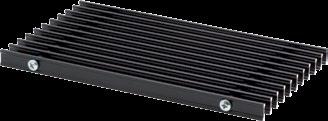
55 Accessories Types and colours of tread-on grilles Longitudinal aluminium tread-on grilles 111D longitudinal fixed grille, anodised in natural aluminium colour 111B longitudinal fixed grille, anodised in black colour 111C longitudinal fixed grille, anodised in brass colour Aluminium and stainless steel roll-up grilles 114D roll-up grille, anodised in natural aluminium colour 114B roll-up grille, anodised in black colour 114C roll-up grille, anodised in brass colour 114SS roll-up grille, stainless steel Wooden roll-up grilles 114W1 oak wood 114W2 ash wood 114W3 wallnut wood 114W4 mahogany wood 55


 VT4 Three way valve")


56 Accessories Water side control 01 Thermostat valve R1/2 ali R3/4, straight 02 Thermostat valve R1/2 or R3/4, angular 03 Radiator shut-off cock R1/2 ali R3/4, straight 04 Radiator shut-off cock R1/2 or R3/4, angular VP2 Two-way valve with ET actuators ON-OF (2-pipe set) VP4 Two-way valve with ET actuators ON-OF (4-pipe set) VT2 Three way valve with ET actuator ON-OF (2-pipe set) VT4 Three way valve with ET actuator ON-OF (4-pipe set) Notes: valve size (R1/2, R3/4 ) depends on the size of heat exchanger connector size (not necessary to state), manual valves are only supplied with the convector but not installed, sets of two- and three-way valves are installed, sets of three-way valves VT2 and VT4 require more space for installation, possibility of installation should be confirmed by the producer before an order. 56
 selection T02 Electronic LCD room thermostat (touch screen) for 2-pipe")
 selection T13 Room thermostat for 4-pipe systems wall")


 or continuous (2-10 Vdc) fan speed regulation manual regime")
57 Accessories Air side control T01 Room thermostat for 2-pipe systems wall installation room temperature setup manual speed selection manual regime (heating cooling) selection T02 Electronic LCD room thermostat (touch screen) for 2-pipe systems semi-flush installation into the enclosed electrical socket setup and display of room temperature manual or auto speed selection manual regime (heating cooling) selection T13 Room thermostat for 4-pipe systems wall installation room temperature setup manual speed selection automatic regime (heating cooling) switching T12 Electronic LCD room thermostat for 2-pipe and 4-pipe systems semi-flush installation into standard electrical socket Φ60 mm (not enclosed) setup and display of room temperature manual or auto speed selection automatic regime (heating cooling) selection possibility to connect an external temperature sensor T20 Electronic LCD room thermostat for continuous control of AC or EC fans for 2-pipe and 4-pipe systems wall installation display of room temperature, set room temperature and parameters manual 3-step (MIN-MED-MAX) or continuous (2-10 Vdc) fan speed regulation manual regime selection (heating cooling auto) 57


 connection to a room")


58 Accessories AT45 Avtotransformer AT45 is designed for 3-step speed control of 1 to max. 6 fans type 45 installed in TKV-13 or TKH-13 floor convectors. AT60 Avtotransformer AT60 is designed for 3-step speed control of 1 to max. 6 fans type 60 installed in TKH-13 floor convectors. RV Relay interface is designed to attach autotransformer AT45 or AT60 in 2- or 4-pipe models of TKV-13 or TKH-13 floor convectors: connection to a room thermostat to control several groups of floor convectors connected to one room thermostat (more than 6 fans in a group) connection to a room thermostat or BMS with 3-step (MIN-MED-MAX) outputs 230 Vac output for fan speed In case when 6 or less ventilators are controlled with a single T01 room thermostat, RV is not needed. 09S This fan speed controller for the TKV-S-13 is used for 3-step regulation of 12V fans, mounted into the TKV-S-13, in connection with the T01 thermostat. We can connect max. 6 fans to one 09S. SC 1 Controller for continuous control of max. 6 AC fans: connection to room thermostat T20 connection to CNS with 2-10 V output for fan speed control Note: Floor convectors with EC fans and control are available upon request only. 58

 Round shaped convector and grille:")


59 Accessories Other 010(xx ) Corner design of convector and grille according to drawing 017 thermal insulation 018 Wooden protection cover 020(Rxxxx) Round shaped convector and grille: according to drawing TK-13 and TKV-13 models roll-up grille only 021 Aluminium frame grille rubber layer AL profile housing H B- nominl width B B+12 mm Note: when ordering accessory 021, lenght and width of housing increase for 12 mm. According to this, the length and width of the grille change also. 028 Level adjusting legs Leveling height (distance to the bottom of floor convector) is mm. Installation possible in models of 105 and 140 mm height only. different project solutions upon request 029 Level adjusting and support legs secommended for installation into false floor set with reinforced housing bracket available upon request 59

60 Accessories Connection for fresh air supply 032 Connection for fresh air supply, size DN 80, without damper. Installation on TK-13, TKV-13 and TKH-13 models, with 140 mm height. Max. air flow rates up 80 m³/h per connection. Different project solutions possible. 033 Connection for fresh air supply with damper, size DN 80. Installation on TK-13, TKV-13 and TKH-13 models, with 140 mm height. Max. air flow rates up 80 m³/h per connection. Available upon request only. Example: TKH x34x14/D/2C/45/032 Custom - made convectors Special versions of floor convectors with non-standard dimensions and technical characteristics can be produced on customer's request and specifications. 60
Heat exchanger. Type WT. For the reheating of airflows in rectangular ducting PD WT 1. 03/2017 DE/en
 X X testregistrierung Heat exchanger Type For the reheating of airflows in rectangular ducting Rectangular hot water heat exchanger for the reheating of airflows, suitable for VAV terminal units Type TVR,
4 Way Reversing Valve
 STANDARD 4 Way Reversing Valve SHF series four-way reversing valves are applicable for heat pump systems such as central, unitary and room air conditioners to realize switching between cooling mode and
MARKET INTRODUCTION System integration
 MARKET INTRODUCTION System integration Air to Water Split System Inverter Driven Nomιnal Capacities : 5-6,5-9 - 11,5 kwth Max LWT= 60 C & Min OAT = -15 C COP>= 4.1 Air to Water Monoblock Inverter Driven
4 Way Reversing Valve
 STANDARD 4 Way Reversing Valve SHF series four-way reversing valves are applicable for heat pump systems such as central, unitary and room air conditioners to realize switching between cooling mode and
UDZ Swirl diffuser. Product facts. Quick-selection. Swirl diffuser UDZ. Product code example:
 UDZ Swirl diffuser Swirl diffuser UDZ, which is intended for installation in a ventilation duct, can be used in premises with a large volume, for example factory premises, storage areas, superstores, halls,
Lowara SPECIFICATIONS
 SH Series Centrifugal pumps entirely made of AISI 36 stainless steel according to EN 733 (ex DIN 24255). Designed to pump hot, cold and moderately aggressive liquids. Available versions: SHE Close-coupled
Instruction Execution Times
 1 C Execution Times InThisAppendix... Introduction DL330 Execution Times DL330P Execution Times DL340 Execution Times C-2 Execution Times Introduction Data Registers This appendix contains several tables
Daewoo Technopark A-403, Dodang-dong, Wonmi-gu, Bucheon-city, Gyeonggido, Korea LM-80 Test Report
 LM-80 Test Report Approved Method: Measuring Lumen Maintenance of LED Light Sources Project Number: KILT1212-U00216 Date: September 17 th, 2013 Requested by: Dongbu LED Co., Ltd 90-1, Bongmyeong-Ri, Namsa-Myeon,
SMD Transient Voltage Suppressors
 SMD Transient Suppressors Feature Full range from 0 to 22 series. form 4 to 60V RMS ; 5.5 to 85Vdc High surge current ability Bidirectional clamping, high energy Fast response time
Aluminum Electrolytic Capacitors (Large Can Type)
") Aluminum Electrolytic Capacitors (Large Can Type) Snap-In, 85 C TS-U ECE-S (U) Series: TS-U Features General purpose Wide CV value range (33 ~ 47,000 µf/16 4V) Various case sizes Top vent construction
Aluminum Electrolytic Capacitors (Large Can Type) Snap-In, 85 C TS-U ECE-S (U) Series: TS-U Features General purpose Wide CV value range (33 ~ 47,000 µf/16 4V) Various case sizes Top vent construction
Group 30. Contents.
 Group 30 Contents Pump type Page Pump type Page Pump type Page 30A(C)...X002H 4 30A(C)...X013H 5 30A(C)...X068H 6 30A(C)...X068HU 7 30A(C)...X136H 8 30A(C)...X136Y 9 30A(C)...X146H 10 30A(C)...X160H 11
Lowara APPLICATIONS MATERIALS. General Catalogue
 FH Series Centrifugal electric pumps according to EN 733 (ex DIN 24255). Electric pumps with pump casing in cast iron and impeller in AISI 36* stainless steel, designed to pump hot, cold and moderately
the smartest energy Floor standing DHW (Domestic Hot Water) storage tanks for Forced Circulation Solar systems
 storage tanks for Forced Circulation Solar systems") the smartest energy Floor standing DHW (Domestic Hot Water) storage tanks for Forced Circulation olar systems www.thermicsol.com 15 Floor standing single coil DHW storage tanks Material: teel sheet EN-10130
the smartest energy Floor standing DHW (Domestic Hot Water) storage tanks for Forced Circulation olar systems www.thermicsol.com 15 Floor standing single coil DHW storage tanks Material: teel sheet EN-10130
Specification. code ±1.0 ±1.0 ±1.0 ±1.0 ±0.5 approx (g)
") High CV-value Long Life > 10 years at 50 C Low ESR and ESL High stability, 10 years shelf life Optimized designs available on request RoHS Compliant application Basic design Smoothing, energy storage,
High CV-value Long Life > 10 years at 50 C Low ESR and ESL High stability, 10 years shelf life Optimized designs available on request RoHS Compliant application Basic design Smoothing, energy storage,
Strain gauge and rosettes
 Strain gauge and rosettes Introduction A strain gauge is a device which is used to measure strain (deformation) on an object subjected to forces. Strain can be measured using various types of devices classified
Surface Mount Multilayer Chip Capacitors for Commodity Solutions
 Surface Mount Multilayer Chip Capacitors for Commodity Solutions Below tables are test procedures and requirements unless specified in detail datasheet. 1) Visual and mechanical 2) Capacitance 3) Q/DF
Engineering Data High-wall Type (3 series) Indoor Unit. Contents MMK-AP0073H MMK-AP0093H MMK-AP0123H MMK-AP0153H MMK-AP0183H MMK-AP0243H.
 Indoor Unit. Contents MMK-AP0073H MMK-AP0093H MMK-AP0123H MMK-AP0153H MMK-AP0183H MMK-AP0243H.") E09-311 Engineering Data High-wall Type (3 series) Indoor Unit Model name: MMK-AP0073H MMK-AP0093H MMK-AP0123H MMK-AP0153H MMK-AP0183H MMK-AP0243H Contents 1 Specifications 2 Dimensions 3 Center of gravity
E09-311 Engineering Data High-wall Type (3 series) Indoor Unit Model name: MMK-AP0073H MMK-AP0093H MMK-AP0123H MMK-AP0153H MMK-AP0183H MMK-AP0243H Contents 1 Specifications 2 Dimensions 3 Center of gravity
Aluminum Electrolytic Capacitors
 Aluminum Electrolytic Capacitors Snap-In, Mini., 105 C, High Ripple APS TS-NH ECE-S (G) Series: TS-NH Features Long life: 105 C 2,000 hours; high ripple current handling ability Wide CV value range (47
SPBW06 & DPBW06 series
 /,, MODEL SELECTION TABLE INPUT ORDER NO. INPUT VOLTAGE (RANGE) NO LOAD INPUT CURRENT FULL LOAD VOLTAGE CURRENT EFFICIENCY (TYP.) CAPACITOR LOAD (MAX.) SPBW06F-03 310mA 3.3V 0 ~ 1500mA 81% 4700μF SPBW06F-05
NMBTC.COM /
 Common Common Vibration Test:... Conforms to JIS C 60068-2-6, Amplitude: 1.5mm, Frequency 10 to 55 Hz, 1 hour in each of the X, Y and Z directions. Shock Test:...Conforms to JIS C 60068-2-27, Acceleration
RAC. Technical Data Book. RAC(Quantum) for North America (R410A, 60Hz, HP) Model : AR09/12/18/24KSFPDWQNCV AR09/12/18/24KSFPDWQXCV
 for North America (R410A, 60Hz, HP) Model : AR09/12/18/24KSFPDWQNCV AR09/12/18/24KSFPDWQXCV") RAC Technical Data Book RAC(Quantum) for North America (R410A, 60Hz, HP) Model : AR09/12/18/24KSFPDWQNCV AR09/12/18/24KSFPDWQXCV History Version Modification Date Remark Ver 1.0 Release RAC (Quantum) TDB
RAC Technical Data Book RAC(Quantum) for North America (R410A, 60Hz, HP) Model : AR09/12/18/24KSFPDWQNCV AR09/12/18/24KSFPDWQXCV History Version Modification Date Remark Ver 1.0 Release RAC (Quantum) TDB
DATA SHEET Surface mount NTC thermistors. BCcomponents
 DATA SHEET 2322 615 1... Surface mount N thermistors Supersedes data of 17th May 1999 File under BCcomponents, BC02 2001 Mar 27 FEATURES High sensitivity High accuracy over a wide temperature range Taped
The Simply Typed Lambda Calculus
 Type Inference Instead of writing type annotations, can we use an algorithm to infer what the type annotations should be? That depends on the type system. For simple type systems the answer is yes, and
Finish: Anticorrosive finish in polyester. Number of motor poles 4=1400 r/min. 50 Hz 6=900 r/min. 50 Hz 8=750 r/min. 50 Hz
 HEP HEPT HEP: Wall-mounted axial fans, with IP65 motor HEPT: Long-cased axial fans, with IP65 motor Wall-mounted axial (HEP) and long-cased (HEPT) fans, with fibreglass-reinforced plastic impeller. Fan:
CSR series. Thick Film Chip Resistor Current Sensing Type FEATURE PART NUMBERING SYSTEM ELECTRICAL CHARACTERISTICS
 FEATURE Operating Temperature: -55 ~ +155 C 3 Watts power rating in 1 Watt size, 1225 package High purity alumina substrate for high power dissipation Long side terminations with higher power rating PART
(1) Describe the process by which mercury atoms become excited in a fluorescent tube (3)
 Describe the process by which mercury atoms become excited in a fluorescent tube (3)") Q1. (a) A fluorescent tube is filled with mercury vapour at low pressure. In order to emit electromagnetic radiation the mercury atoms must first be excited. (i) What is meant by an excited atom? (1) (ii)
Q1. (a) A fluorescent tube is filled with mercury vapour at low pressure. In order to emit electromagnetic radiation the mercury atoms must first be excited. (i) What is meant by an excited atom? (1) (ii)
Swirl diffusers, Variable swirl diffusers Swirl diffusers
 , Variable swirl diffusers Swirl diffuser OD-9 Square or round front mask Square or radial deflector arrangement Plastic deflectors Possible volume control damper in spigot Foam sealing on the flange St
ZLW Series. Single-stage Monoblock Centrifugal Pump ZL PUMP GROUP.,LTD
 ZLW Series Single-stage Monoblock Centrifugal Pump ZL PUMP GROUP.,LTD 1 Application Apply as the transportation of liquids in the fields of air condition, heating, sanitary water, water treatment cooling,
RSDW08 & RDDW08 series
 /,, MODEL SELECTION TABLE INPUT ORDER NO. INPUT VOLTAGE (RANGE) NO LOAD INPUT CURRENT FULL LOAD VOLTAGE CURRENT EFFICIENCY (Typ.) CAPACITOR LOAD (MAX.) RSDW08F-03 344mA 3.3V 2000mA 80% 2000μF RSDW08F-05
Metal Oxide Varistors (MOV) Data Sheet
 Data Sheet") Φ SERIES Metal Oxide Varistors (MOV) Data Sheet Features Wide operating voltage (V ma ) range from 8V to 0V Fast responding to transient over-voltage Large absorbing transient energy capability Low clamping
Φ SERIES Metal Oxide Varistors (MOV) Data Sheet Features Wide operating voltage (V ma ) range from 8V to 0V Fast responding to transient over-voltage Large absorbing transient energy capability Low clamping
Other Test Constructions: Likelihood Ratio & Bayes Tests
 Other Test Constructions: Likelihood Ratio & Bayes Tests Side-Note: So far we have seen a few approaches for creating tests such as Neyman-Pearson Lemma ( most powerful tests of H 0 : θ = θ 0 vs H 1 :
Thermistor (NTC /PTC)
") ISO/TS16949 ISO 9001 ISO14001 2015 Thermistor (NTC /PTC) GNTC (Chip in Glass Thermistor) SMD NTC Thermistor SMD PTC Thermistor Radial type Thermistor Bare Chip Thermistor (Gold & silver Electrode) 9B-51L,
ISO/TS16949 ISO 9001 ISO14001 2015 Thermistor (NTC /PTC) GNTC (Chip in Glass Thermistor) SMD NTC Thermistor SMD PTC Thermistor Radial type Thermistor Bare Chip Thermistor (Gold & silver Electrode) 9B-51L,
SERIES DATASHEET INDUCTORS RF INDUCTORS (MRFI SERIES)
") SERIES DATASHEET INDUCTORS RF INDUCTORS (MRFI SERIES) (8) 95-8365 venkel.com Features: RoHS Compliant and Halogen Free Good Q values High SRF range: 1nH to 47uH Tolerance: ±.2nH, ±.3nH, ±2%, ±5%, ±1% High
SERIES DATASHEET INDUCTORS RF INDUCTORS (MRFI SERIES) (8) 95-8365 venkel.com Features: RoHS Compliant and Halogen Free Good Q values High SRF range: 1nH to 47uH Tolerance: ±.2nH, ±.3nH, ±2%, ±5%, ±1% High
Study of In-vehicle Sound Field Creation by Simultaneous Equation Method
 Study of In-vehicle Sound Field Creation by Simultaneous Equation Method Kensaku FUJII Isao WAKABAYASI Tadashi UJINO Shigeki KATO Abstract FUJITSU TEN Limited has developed "TOYOTA remium Sound System"
1000 VDC 1250 VDC 125 VAC 250 VAC J K 125 VAC, 250 VAC
 Metallized Polyester Film Capacitor Type: ECQE(F) Non-inductive construction using metallized Polyester film with flame retardant epoxy resin coating Features Self-healing property Excellent electrical
Applications Water distribution
 1 FH Series Centrifugal electric pumps according to EN 733 (ex DIN 24255). Electric pumps with pump casing in cast iron designed to pump clean, chemically non-aggressive water and liquids. Available versions:
2R2. 2 (L W H) [mm] Wire Wound SMD Power Inductor. Nominal Inductance Packing Tape & Reel. Design Code M ±20%
![2R2. 2 (L W H) [mm] Wire Wound SMD Power Inductor. Nominal Inductance Packing Tape & Reel. Design Code M ±20%](/thumbs/78/78109689.jpg "2R2. 2 (L W H) [mm] Wire Wound SMD Power Inductor. Nominal Inductance Packing Tape & Reel. Design Code M ±20%") Wire Wound SMD Power Inductors WPN Series Operating temperature range : -40 ~+125 (Including self-heating) FEATURES Fe base metal material core provides large saturation current Metallization on ferrite
Wire Wound SMD Power Inductors WPN Series Operating temperature range : -40 ~+125 (Including self-heating) FEATURES Fe base metal material core provides large saturation current Metallization on ferrite
Linear diffuser. Dimensions. Description
 Dimensions -- + D -- Description is a rectangular linear diffuser in aluminium. is suitable for both supply and exhaust air. is equipped with air guide baffles, making it possible to use for horizontal
EE512: Error Control Coding
 EE512: Error Control Coding Solution for Assignment on Finite Fields February 16, 2007 1. (a) Addition and Multiplication tables for GF (5) and GF (7) are shown in Tables 1 and 2. + 0 1 2 3 4 0 0 1 2 3
Shenzhen Lys Technology Co., Ltd
 Carbide drawing dies Properties of grade Grade Density TRS Average Grain size Hardness (HRA) (g/cm3) (MPa) (ųm) YL01 15.25 93.5 3300 0.8 YL10.2 14.5 92.0 4000 0.8 YG6 14.95 90 2400 1.6 YG6X 14.95 91.5
derivation of the Laplacian from rectangular to spherical coordinates
 derivation of the Laplacian from rectangular to spherical coordinates swapnizzle 03-03- :5:43 We begin by recognizing the familiar conversion from rectangular to spherical coordinates (note that φ is used
SCOPE OF ACCREDITATION TO ISO 17025:2005
 SCOPE OF ACCREDITATION TO ISO 17025:2005 TFF CORPORATION TEKTRONIX COMPANY 1-14-1 Midorigaoka, Naka-gun, Ninomiya-machi, Kanagawa Pref. 259-0132 JAPAN Hideki Yuyama Phone: 81 463 70 5634 CALIBRATION Valid
the total number of electrons passing through the lamp.
 1. A 12 V 36 W lamp is lit to normal brightness using a 12 V car battery of negligible internal resistance. The lamp is switched on for one hour (3600 s). For the time of 1 hour, calculate (i) the energy
ΕΙΣΑΓΩΓΗ ΣΤΗ ΣΤΑΤΙΣΤΙΚΗ ΑΝΑΛΥΣΗ
 ΕΙΣΑΓΩΓΗ ΣΤΗ ΣΤΑΤΙΣΤΙΚΗ ΑΝΑΛΥΣΗ ΕΛΕΝΑ ΦΛΟΚΑ Επίκουρος Καθηγήτρια Τµήµα Φυσικής, Τοµέας Φυσικής Περιβάλλοντος- Μετεωρολογίας ΓΕΝΙΚΟΙ ΟΡΙΣΜΟΙ Πληθυσµός Σύνολο ατόµων ή αντικειµένων στα οποία αναφέρονται
Capacitors - Capacitance, Charge and Potential Difference
 Capacitors - Capacitance, Charge and Potential Difference Capacitors store electric charge. This ability to store electric charge is known as capacitance. A simple capacitor consists of 2 parallel metal
2013 REV 01 ELECTRONICS CAPACITORS. DC Applications Metallized Polypropylene Film Self Healing
 2013 REV 01 POWER EECTRONICS CAPACITORS C Applications Metallized Polypropylene Film Healing OUR MISSION: POWER EECTRONICS AN SPECIA CAPACITORS M.V. PFC CAPACITORS AN BANKS IGHTING CAPACITORS MOTOR RUN
TODA-ISU Corporation. SMD Power Inductor. SPI series. SMD Team
 SMD Power Inductor SPI series TODA-ISU Corporation Advantages & Applications Advantages Low profile High current capability & Low DCR Low temperature rise Increased thermal efficiency Patent (Coil Integrated
Εγκατάσταση λογισμικού και αναβάθμιση συσκευής Device software installation and software upgrade
 Για να ελέγξετε το λογισμικό που έχει τώρα η συσκευή κάντε κλικ Menu > Options > Device > About Device Versions. Στο πιο κάτω παράδειγμα η συσκευή έχει έκδοση λογισμικού 6.0.0.546 με πλατφόρμα 6.6.0.207.
ST5224: Advanced Statistical Theory II
 ST5224: Advanced Statistical Theory II 2014/2015: Semester II Tutorial 7 1. Let X be a sample from a population P and consider testing hypotheses H 0 : P = P 0 versus H 1 : P = P 1, where P j is a known
Math 6 SL Probability Distributions Practice Test Mark Scheme
 Math 6 SL Probability Distributions Practice Test Mark Scheme. (a) Note: Award A for vertical line to right of mean, A for shading to right of their vertical line. AA N (b) evidence of recognizing symmetry
Polymer PTC Resettable Fuse: KRG Series
 Features 1. RoHS & Halogen-Free (HF) compliant 2. Radial leaded devices 3. Broadest range of resettable devices available in the industry 4. Hold current ratings from 0.1 to 3.75A 5. Maximum voltage is
Η σειρά EUROPA σχεδιάστηκε για να δημιουργεί αίθρια. με δυνατότητα παραθύρων οροφής. Προσφέρει απόλυτη αντοχή, τέλεια
 Η σειρά EUROPA 7000 σχεδιάστηκε για να δημιουργεί αίθρια με δυνατότητα παραθύρων οροφής. Προσφέρει απόλυτη αντοχή, τέλεια λειτουργικότητα και όμορφο αισθητικά αποτέλεσμα, επιτρέποντας την άμεση επαφή με
Ceramic PTC Thermistor Overload Protection
 FEATURES compliant CPTD type are bare disc type CPTL type are leaded Low, medium and high voltage ratings Low resistance; Small size No need to reset supply after overload No noise generated Stable over
Thi=Τ1. Thο=Τ2. Tci=Τ3. Tco=Τ4. Thm=Τ5. Tcm=Τ6
 1 Τ.Ε.Ι. ΑΘΗΝΑΣ / Σ.ΤΕ.Φ. ΤΜΗΜΑ ΕΝΕΡΓΕΙΑΚΗΣ ΤΕΧΝΟΛΟΓΙΑΣ ΕΡΓΑΣΤΗΡΙΟ ΜΕΤΑΔΟΣΗΣ ΘΕΡΜΟΤΗΤΟΣ Οδός Αγ.Σπυρίδωνος,12210 Αιγάλεω,Αθήνα Τηλ.: 2105385355, email: ptsiling@teiath.gr H ΕΠΙΔΡΑΣΗ ΠΑΡΟΧΗΣ ΟΓΚΟΥ ΣΤΗΝ
SMD Power Inductor. - SPRH127 Series. Marking. 1 Marking Outline: 1 Appearance and dimensions (mm)
") Marking Outline: Low DCR, high rated current. Magnetic shielded structure Lead free product, RoHS compliant. RoHS Carrier tape packing, suitable for SMT process. SMT Widely used in buck converter, laptop,
Marking Outline: Low DCR, high rated current. Magnetic shielded structure Lead free product, RoHS compliant. RoHS Carrier tape packing, suitable for SMT process. SMT Widely used in buck converter, laptop,
RC series Thick Film Chip Resistor
 RC series Thick Film Chip Resistor Features» Small size and light weight» Compatible with wave and reflow soldering» Suitable for lead free soldering» RoHS compliant & Halogen Free Applications Configuration»
Main source: "Discrete-time systems and computer control" by Α. ΣΚΟΔΡΑΣ ΨΗΦΙΑΚΟΣ ΕΛΕΓΧΟΣ ΔΙΑΛΕΞΗ 4 ΔΙΑΦΑΝΕΙΑ 1
 Main source: "Discrete-time systems and computer control" by Α. ΣΚΟΔΡΑΣ ΨΗΦΙΑΚΟΣ ΕΛΕΓΧΟΣ ΔΙΑΛΕΞΗ 4 ΔΙΑΦΑΝΕΙΑ 1 A Brief History of Sampling Research 1915 - Edmund Taylor Whittaker (1873-1956) devised a
NTC thermistors for temperature measurement
 NTC thermistors for temperature measurement SMD NTC thermistors with nickel barrier termination, case size 0603 Series/Type: Date: June 2008 EPCOS AG 2008. Reproduction, publication and dissemination of
ΠΕΡΙΕΧΟΜΕΝΑ. Κεφάλαιο 1: Κεφάλαιο 2: Κεφάλαιο 3:
 4 Πρόλογος Η παρούσα διπλωµατική εργασία µε τίτλο «ιερεύνηση χωρικής κατανοµής µετεωρολογικών µεταβλητών. Εφαρµογή στον ελληνικό χώρο», ανατέθηκε από το ιεπιστηµονικό ιατµηµατικό Πρόγραµµα Μεταπτυχιακών
Calculating the propagation delay of coaxial cable
 Your source for quality GNSS Networking Solutions and Design Services! Page 1 of 5 Calculating the propagation delay of coaxial cable The delay of a cable or velocity factor is determined by the dielectric
C4C-C4H-C4G-C4M MKP Series AXIAL CAPACITORS PCB APPLICATIONS
 C4C-C4H-C4G-C4M AXIAL CAPACITORS PCB APPLICATIONS General characteristics - Self-Healing - Low losses - High ripple current - High contact reliability - Suitable for high frequency applications 40 ±5 L
CSK series. Current Sensing Chip Resistor. Features. Applications. Construction FAITHFUL LINK
 CSK series Current Sensing Chip Resistor Features» 3 Watts power rating in 1 Watt size, 1225 Package» Low TCR of ±100 PPM/ C» Resistance values from 1m to 1 ohm» High purity alumina substrate for high
[bar] 0,5 (7.3 PSI) maximum continuous pressure - maximum working pressure, at which the pump can be operated without time limitation.
![[bar] 0,5 (7.3 PSI) maximum continuous pressure - maximum working pressure, at which the pump can be operated without time limitation.](/thumbs/93/111947477.jpg "[bar] 0,5 (7.3 PSI) maximum continuous pressure - maximum working pressure, at which the pump can be operated without time limitation.") Gear Pump High Performance Version GP up to, cm (.7 inch ) p max bar ( PSI) Speed from to RPM Technical Features Nominal pressure bar, peak pressure bar High quality aluminum alloys pump with xial playe
Gear Pump High Performance Version GP up to, cm (.7 inch ) p max bar ( PSI) Speed from to RPM Technical Features Nominal pressure bar, peak pressure bar High quality aluminum alloys pump with xial playe
Thin Film Chip Resistors
 FEATURES PRECISE TOLERANCE AND TEMPERATURE COEFFICIENT EIA STANDARD CASE SIZES (0201 ~ 2512) LOW NOISE, THIN FILM (NiCr) CONSTRUCTION REFLOW SOLDERABLE (Pb FREE TERMINATION FINISH) Type Size EIA PowerRating
Right Rear Door. Let's now finish the door hinge saga with the right rear door
 Right Rear Door Let's now finish the door hinge saga with the right rear door You may have been already guessed my steps, so there is not much to describe in detail. Old upper one file:///c /Documents
[bar] 0,5 (7.3 PSI) maximum continuous pressure - maximum working pressure, at which the pump can be operated without time limitation.
![[bar] 0,5 (7.3 PSI) maximum continuous pressure - maximum working pressure, at which the pump can be operated without time limitation.](/thumbs/75/72614325.jpg "[bar] 0,5 (7.3 PSI) maximum continuous pressure - maximum working pressure, at which the pump can be operated without time limitation.") Gear Pump High Performance Version GP up to, cm (.7 inch ) p max bar ( PSI) Speed from to RPM Technical Features Operating pressure bar, Peak pressure bar High-strength quality aluminum alloys pump with
Gear Pump High Performance Version GP up to, cm (.7 inch ) p max bar ( PSI) Speed from to RPM Technical Features Operating pressure bar, Peak pressure bar High-strength quality aluminum alloys pump with
THICK FILM LEAD FREE CHIP RESISTORS
 Features Suitable for lead free soldering. Compatible with flow and reflow soldering Applications Consumer Electronics Automotive industry Computer Measurement instrument Electronic watch and camera Configuration
Precision Metal Film Fixed Resistor Axial Leaded
 Features EIA standard colour-coding Non-Flame type available Low noise and voltage coefficient Low temperature coefficient range Wide precision range in small package Too low or too high ohmic value can
High Frequency Chip Inductor / CF TYPE
 High Frequency Chip Inductor / CF TYPE.Features: 1.Closed magnetic circuit avoids crosstalk. 2.S.M.T. type. 3.Excellent solderability and heat resistance. 4.High realiability. 5.The products contain no
Safety Barriers. 6 Safety Barriers KP00 III en Preferred products in stock or available at short notice
 5-- KP III en Contents Single-Channel INTRINSPAK 9 8 Dual-Channel INTRINSPAK 9 with Electronic Current Limitation INTRINSPAK 94 You will find further information on the Internet www.stahl.de General Information
2. Laser Specifications 2 1 Specifications IK4301R D IK4401R D IK4601R E IK4101R F. Linear Linear Linear Linear
 2. Laser Specifications 2 1 Specifications IK4301R D IK4401R D IK4601R E IK4101R F 441.6 441.6 441.6 441.6 30 50 70 100 TEM00 TEM00 TEM00 TEM00 BEAM DIAMETER ( 1/e2) 1.1 1.1 1.2 1.2 0.5 0.5 0.5 0.4 RATIO
PRODUCT IDENTIFICATION SWPA 3012 S 1R0 N T
 Wire Wound SMD Power Inductors SWPA Series Operating temperature range: -4 ~+25 (Including self-heating) FEATURES Magnetic-resin shielded conruction reduces buzz noise to ultra-low levels Metallization
Εργαστήριο Ανάπτυξης Εφαρμογών Βάσεων Δεδομένων. Εξάμηνο 7 ο
 Εργαστήριο Ανάπτυξης Εφαρμογών Βάσεων Δεδομένων Εξάμηνο 7 ο Procedures and Functions Stored procedures and functions are named blocks of code that enable you to group and organize a series of SQL and PL/SQL
Chilisin Electronics Singapore Pte Ltd
 hilisin Electronics ingapore Pte Ltd High urrent hip Beads, PBY eries Feature: Our MD High urrent hips Beads is specially designed to with tand large urrents while providing a means of EMI/RFI attenuation
Multilayer Chip Inductor
 Features -Monolithic structure for high reliability -High self-resonant frequency -Excellent solderability and high heat resistance Construction Applications -RF circuit in telecommunication and other
3 V, 900 MHz LOW NOISE SI MMIC AMPLIFIER
 V, 9 MHz LOW NOISE SI MMIC AMPLIFIER UPC78T FEATURES.8 db NOISE FIGURE LOW VOLTAGE - LOW CURRENT: ma at V LOW POWER CONSUMPTION: 8 mw TYP SUPER SMALL PACKAGE TAPE AND REEL PACKAGING OPTION AVAILABLE DESCRIPTION
Current Sensing Chip Resistor SMDL Series Size: 0201/0402/0603/0805/1206/1010/2010/2512/1225/3720/7520. official distributor of
 Product: Current Sensing Chip Resistor SMDL Series Size: 0201/0402/0603/0805/1206/1010/2010/2512/1225/3720/7520 official distributor of Current Sensing Chip Resistor (SMDL Series) 1. Features -3 Watts
3 V, 1500 MHz Si MMIC WIDEBAND AMPLIFIER
 V, MHz Si MMIC WIDEBAND AMPLIFIER UPC7T FEATURES WIDE FREQUENCY RESPONSE: MHz LOW VOLTAGE OPERATION: V NOMINAL (. MIN) LOW POWER CONSUMPTION:. mw TYP SUPER SMALL PACKAGE TAPE AND REEL PACKAGING OPTION
COPELAND SCROLL AIR COOLED CONDENSING UNITS
 R404A Refrigerant Scroll R507A Refrigerant R134A Refrigerant STANDARD UNIT WITH: Copeland ZB Scroll Compressors for medium temp applications on R404A/R507A/R134A Copeland ZB & ZF Scroll Compressors for
First Sensor Quad APD Data Sheet Part Description QA TO Order #
 Responsivity (/W) First Sensor Quad PD Data Sheet Features Description pplication Pulsed 16 nm laser detection RoHS 211/65/EU Light source positioning Laser alignment ø mm total active area Segmented in
Potential Dividers. 46 minutes. 46 marks. Page 1 of 11
 Potential Dividers 46 minutes 46 marks Page 1 of 11 Q1. In the circuit shown in the figure below, the battery, of negligible internal resistance, has an emf of 30 V. The pd across the lamp is 6.0 V and
Replacement Guide. Wilo Circulators for Heating and Secondary Hot Water Circulation. Pioneering for You
 Replacement Guide Wilo Circulators for Heating and Secondary Hot Water Circulation 2013 Pioneering for You Grundfos Single pumps Wilo new High-efficiency pumps infinitely variable, 1~230V, 50Hz Stratos
GAUGE BLOCKS. Grade 0 Tolerance for the variation in length. Limit deviation of length. ± 0.25μm. 0.14μm ±0.80μm. ± 1.90μm. ± 0.40μm. ± 1.
 GAUGE BLOCKS Accuracy according to ISO650 Nominal length (mm) Limit deviation of length Grade 0 Tolerance for the variation in length Grade Grade Grade Grade 2 Limit deviations of Tolerance for the Limit
DETERMINATION OF THERMAL PERFORMANCE OF GLAZED LIQUID HEATING SOLAR COLLECTORS
 ΕΘΝΙΚΟ ΚΕΝΤΡΟ ΕΡΕΥΝΑΣ ΦΥΣΙΚΩΝ ΕΠΙΣΤΗΜΩΝ ΗΜΟΚΡΙΤΟΣ / DEMOKRITOS NATIONAL CENTER FOR SCIENTIFIC RESEARCH ΕΡΓΑΣΤΗΡΙΟ ΟΚΙΜΩΝ ΗΛΙΑΚΩΝ & ΑΛΛΩΝ ΕΝΕΡΓΕΙΑΚΩΝ ΣΥΣΤΗΜΑΤΩΝ LABORATORY OF TESTIN SOLAR & OTHER ENERY
FEATURES APPLICATION PRODUCT T IDENTIFICATION PRODUCT T DIMENSION MAG.LAYERS
 FEATURES RoHS compliant. Super low resistance, ultra high current rating. High performance (I sat) realized by metal dust core. Frequency Range: up to 1MHz. APPLICATION PDA, notebook, desktop, and server
3 V, 900 MHz Si MMIC AMPLIFIER
 V, 9 MHz Si MMIC AMPLIFIER UPC77T FEATURES LOW VOLTAGE - LOW CURRENT: ma at V LOW POWER CONSUMPTION: mw TYP SUPER SMALL PACKAGE TAPE AND REEL PACKAGING OPTION AVAILABLE DESCRIPTION The UPC77T is a Silicon
Γιπλυμαηική Δπγαζία. «Ανθπυποκενηπικόρ ζσεδιαζμόρ γέθςπαρ πλοίος» Φοςζιάνηρ Αθανάζιορ. Δπιβλέπυν Καθηγηηήρ: Νηθφιανο Π. Βεληίθνο
 ΔΘΝΙΚΟ ΜΔΣΟΒΙΟ ΠΟΛΤΣΔΥΝΔΙΟ ΥΟΛΗ ΝΑΤΠΗΓΩΝ ΜΗΥΑΝΟΛΟΓΩΝ ΜΗΥΑΝΙΚΩΝ Γιπλυμαηική Δπγαζία «Ανθπυποκενηπικόρ ζσεδιαζμόρ γέθςπαρ πλοίος» Φοςζιάνηρ Αθανάζιορ Δπιβλέπυν Καθηγηηήρ: Νηθφιανο Π. Βεληίθνο Σπιμελήρ Δξεηαζηική
65W PWM Output LED Driver. IDLV-65 series. File Name:IDLV-65-SPEC
 ~ A File Name:IDLV65SPEC 07050 SPECIFICATION MODEL OUTPUT OTHERS NOTE DC VOLTAGE RATED CURRENT RATED POWER DIMMING RANGE VOLTAGE TOLERANCE PWM FREQUENCY (Typ.) SETUP TIME Note. AUXILIARY DC OUTPUT Note.
APPLICATIONS TECHNOLOGY. Leaded Discs N.03 N.06 N.09
 NC Disc hermistors ND 03/06/09 NE 03/06/09 NV 06/09 APPLICAIONS ND or NE: Commerical, Industrial and Automotive Applications AEC-Q200 Qualified NV: Professional Applicationsl Alarm and temperature measurement
Monolithic Crystal Filters (M.C.F.)
") Monolithic Crystal Filters (M.C.F.) MCF (MONOLITHIC CRYSTAL FILTER) features high quality quartz resonators such as sharp cutoff characteristics, low loss, good inter-modulation and high stability over
Monolithic Crystal Filters (M.C.F.) MCF (MONOLITHIC CRYSTAL FILTER) features high quality quartz resonators such as sharp cutoff characteristics, low loss, good inter-modulation and high stability over
Ventilated Distribution Transformers
 General Purpose Energy efficient dry-type transformers 600 Volt Class, isolation type, single and three phase, 1 through 00. Indoor and outdoor models available. Accessories and Optional Styles trostatic
2.5 GHz SILICON MMIC WIDE-BAND AMPLIFIER
 . GHz SILICON MMIC WIDE-BAND AMPLIFIER UPC79T FEATURES WIDE FREQUENCY RESPONSE:. GHz 3 GAIN vs. FREQUENCY HIGH GAIN: 3 db (UPC79T) SATURATED OUTPUT POWER: +. dbm (UPC79T) INTERNAL CURRENT REGULATION MINIMIZES
5.4 The Poisson Distribution.
 The worst thing you can do about a situation is nothing. Sr. O Shea Jackson 5.4 The Poisson Distribution. Description of the Poisson Distribution Discrete probability distribution. The random variable
2 Composition. Invertible Mappings
 Arkansas Tech University MATH 4033: Elementary Modern Algebra Dr. Marcel B. Finan Composition. Invertible Mappings In this section we discuss two procedures for creating new mappings from old ones, namely,
MATRIX. EBARA PUMPS EUROPE S.p.A. HORIZONTAL MULTISTAGE PUMPS
 CONTENTS Page - SPECIFICATIONS 200 PUMP SPECIFICATION 200 TYPE KEY 201 SELECTION CHART 202 SELECTION CHART 203 PERFORMANCE CURVE 3 ( 2-3-4-5 impellers ) 204 PERFORMANCE CURVE 3 ( 6-7-8-9 impellers ) 205
Surface Mount Aluminum Electrolytic Capacitors
 FEATURES CYLINDRICAL V-CHIP CONSTRUCTION LOW COST, GENERAL PURPOSE, 2000 HOURS AT 85 O C NEW EXPANDED CV RANGE (up to 6800µF) ANTI-SOLVENT (2 MINUTES) DESIGNED FOR AUTOMATIC MOUNTING AND REFLOW SOLDERING
LS series ALUMINUM ELECTROLYTIC CAPACITORS CAT.8100D. Specifications. Drawing. Type numbering system ( Example : 200V 390µF)
") Snap-in Terminal Type, 85 C Standard Withstanding 3000 hours application of rated ripple current at 85 C. Compliant to the RoHS directive (2011/65/EU). LS Smaller LG Specifications Item Category Temperature
Snap-in Terminal Type, 85 C Standard Withstanding 3000 hours application of rated ripple current at 85 C. Compliant to the RoHS directive (2011/65/EU). LS Smaller LG Specifications Item Category Temperature
0.635mm Pitch Board to Board Docking Connector. Lead-Free Compliance
 .635mm Pitch Board to Board Docking Connector Lead-Free Compliance MINIDOCK SERIES MINIDOCK SERIES Features Specifications Application.635mm Pitch Connector protected by Diecasted Zinc Alloy Metal Shell
Operating Temperature Range ( C) ±1% (F) ± ~ 1M E-24 NRC /20 (0.05) W 25V 50V ±5% (J) Resistance Tolerance (Code)
 ±1% (F) ± ~ 1M E-24 NRC /20 (0.05) W 25V 50V ±5% (J) Resistance Tolerance (Code)") FEATURES EIA STANDARD SIZING 0201(1/20), 0402(1/16), 0603(1/10), 0805(1/8), 1206(1/4), 1210(1/3), 2010(3/4) AND 2512(1) METAL GLAZED THICK FILM ON HIGH PURITY ALUMINA SUBSTRATE..(CERMET) PROVIDES UNIFORM
FEATURES EIA STANDARD SIZING 0201(1/20), 0402(1/16), 0603(1/10), 0805(1/8), 1206(1/4), 1210(1/3), 2010(3/4) AND 2512(1) METAL GLAZED THICK FILM ON HIGH PURITY ALUMINA SUBSTRATE..(CERMET) PROVIDES UNIFORM
The challenges of non-stable predicates
 The challenges of non-stable predicates Consider a non-stable predicate Φ encoding, say, a safety property. We want to determine whether Φ holds for our program. The challenges of non-stable predicates