High speed Hohe Drehzahl Vitesse élevée Alta velocità Low speed Niedrige Drehzahl Petite vitesse Bassa velocità Stopper Stopper Butée Fermo
|
|
|
- Ευσταχηιος Αλαφούζος
- 8 χρόνια πριν
- Προβολές:
Transcript
1 Impact Drill Schlagbohrmaschine Perceuse percussion Trapano a percussione Klop-boormachine Taladro de percusión Berbequim com percussão Κρουστικο δραπανο DV 16V Read through carefully and understand these instructions before use. Diese Anleitung vor Benutzung des Werkzeugs sorgfältig durchlesen und verstehen. Lire soigneusement et bien assimiler ces instructions avant usage. Prima dell uso leggere attentamente e comprendere queste istruzioni. Deze gebruiksaanwijzing s.v.p. voor gebruik zorgvuldig doorlezen. Leer cuidadosamente y comprender estas instrucciones antes del uso. Antes de usar, leia com cuidado para assimilar estas instruções. ιαβάστε προσεκτικά και κατανοήσετε αυτές τις οδηγίες πριν τη χρήση. Handling instructions Bedienungsanleitung Mode d emploi Istruzioni per l uso Gebruiksaanwijzing Instrucciones de manejo Instruções de uso Οδηγίες χειρισµού

2 A L R 5 6 B C 8 F D E 1

3 9 10 G I H J 8 2
4 A B C D E F G H I J English Deutsch Français Italiano Drill chuck Bohrfutter Mandrin Mandrino trapano Chuck wrench Futterschlüssel Clé de serrage Chiave mandrino Tighten Anziehen Serrer Stringere Loosen Lösen Desserrer Allentare Sleeve Manschette Manchon Collare Ring Ring Anneau Anello Side handle Seitengriff Poignée latérale Maniglia laterale Switch trigger Abzugschalter Gâchette Grilletto interruttore Push button Druckknopf Bouton poussoir Pulsante R mark Markierung R Repère R Segno R L mark Markierung L Repère L Segno L Depth gauge Tiefenlehre Jauge de profondeur Calibro di profondità Change lever Umschalthebel Levier de changement Leva di cambiamento Impact Schlagbohre Percussion Impatto Rotation Bohren Rotation Rotazione Hook (A) Haken (A) Crochet (A) Gancio (A) Speed control dial Drehzahlskala Molette de commande de la vitesse Comando di velocità High speed Hohe Drehzahl Vitesse élevée Alta velocità Low speed Niedrige Drehzahl Petite vitesse Bassa velocità Stopper Stopper Butée Fermo A B C D E F G H I J Nederlands Español Português Ελληνικά Boorkop Boorkopsleutel Aandraaien Losdraaien Klembus Ring Zijhendel Trekkerschakelaar Drukknop R merkteken L merkteken Dieptemeter Wisselhendel Slagboor Rotatie Haak (A) Toerentalregeling Hoog toerental Laag toerental Stopper PortabrocasMandril Llave Apretar Aflojar Manguito Anillo Asa lateral Interruptor de gatillo Botón pulsador Marca R Marca L Calibrador de profundidad Palanca de cambio Impacto Rotación Herramienta (A) Dial de control de velocidad Alta velocidad Baja velocidad Tope Mandril Chave do mandril Apertar Afrouxar Manguito Anel Empunhadura lateral Interruptor de gatilho Botão-interruptor Marca R Marca L Sonda Seletor Impacto Rotação Gancho (A) Dial de controle de velocidade rotação Baixa rotação Obturador Σφικτήρας δραπάνου Κλειδί σφικτήρα Σφίξτε Χαλαρώστε Συνδετικός δακτύλιος ακτύλιος Πλευρική λαβή Σκανδάλη διακόπτης Κουµπί ώθησης R σηµάδι L σηµάδι Μετρητής βάθους Μοχλός αλλαγής Κρούση Περιστροφή Γάντζος (Α) Καντράν ελέγχου ταχύτητας Υψηλή ταχύτητα Χαµηλή ταχύτητα Στόπερ 3
 Haken (A) Crochet (A)")
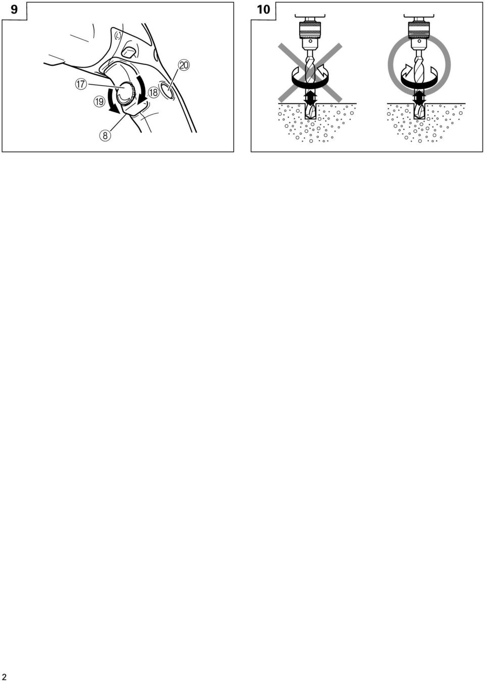
5 English GENERAL OPERATIONAL PRECAUTIONS WARNING! When using electric tools, basic safety precautions should always be followed to reduce the risk of fire, electric shock and personal injury, including the following. Read all these instructions before operating this product and save these instructions. For safe operations: 1. Keep work area clean. Cluttered areas and benches invite injuries. 2. Consider work area environment. Do not expose power tools to rain. Do not use power tools in damp or wet locations. Keep work area well lit. Do not use power tools where there is risk to cause fire or explosion. 3. Guard against electric shock. Avoid body contact with earthed or grounded surfaces. (e.g. pipes, radiators, ranges, refrigerators). 4. Keep children and infirm persons away. Do not let visitors touch the tool or extension cord. All visitors should be kept away from work area. 5. Store idle tools. When not in use, tools should be stored in a dry, high or locked up place, out of reach of children and infirm persons. 6. Do not force the tool. It will do the job better and safer at the rate for which it was intended. 7. Use the right tool. Do not force small tools or attachments to do the job of a heavy duty tool. Do not use tools for purposes not intended; for example, do not use circular saw to cut tree limbs or logs. 8. Dress properly. Do not wear loose clothing or jewelry, they can be caught in moving parts. Rubber gloves and non-skid footwear are recommended when working outdoors. Wear protecting hair covering to contain long hair. 9. Use eye protection. Also use face or dust mask if the cutting operation is dusty. 10. Connect dust extraction equipment. If devices are provided for the connection of dust extraction and collection facilities ensure these are connected and properly used. 11. Do not abuse the cord. Never carry the tool by the cord or yank it to disconnect it from the receptacle. Keep the cord away from heat, oil and sharp edges. 12. Secure work. Use clamps or a vise to hold the work. It is safer than using your hand and it frees both hands to operate tool. 13. Do not overreach. Keep proper footing and balance at all times. 14. Maintain tools with care. Keep cutting tools sharp and clean for better and safer performance. Follow instructions for lubrication and changing accessories. Inspect tool cords periodically and if damaged, have it repaired by authorized service center. Inspect extension cords periodically and replace, if damaged. Keep handles dry, clean, and free from oil and grease. 15. Disconnect tools. When not in use, before servicing, and when changing accessories such as blades, bits and cutters. 16. Remove adjusting keys and wrenches. Form the habit of checking to see that keys and adjusting wrenches are removed from the tool before turning it on. 17. Avoid unintentional starting. Do not carry a pluggedin tool with a finger on the switch. Ensure switch is off when plugging in. 18. Use outdoor extension leads. When tool is used outdoors, use only extension cords intended for outdoor use. 19. Stay alert. Watch what you are doing. Use common sense. Do not operate tool when you are tired. 20. Check damaged parts. Before further use of the tool, a guard or other part that is damaged should be carefully checked to determine that it will operate properly and perform its intended function. Check for alignment of moving parts, free running of moving parts, breakage of parts, mounting and any other conditions that may affect its operation. A guard or other part that is damaged should be properly repaired or replaced by an authorized service center unless otherwise indicated in this handling instructions. Have defective switches replaced by an authorized service center. Do not use the tool if the switch does not turn it on and off. 21. Warning The use of any accessory or attachment, other than those recommended in this handling instructions, may present a risk of personal injury. 22. Have your tool repaired by a qualified person. This electric tool is in accordance with the relevant safety requirements. Repairs should only be carried out by qualified persons using original spare parts. Otherwise this may result in considerable danger to the user. PRECAUTIONS ON USING IMPACT DRILL 1. Before drilling into walls, ceilings or floors, ensure that there are no concealed power cables inside. 2. When boring concrete or similar hard materials in IMPACT mode, push the R-side of the push button. (Fig. 10) 4

6 English SPECIFICATIONS Voltage (by areas)* (110V, 220V, 230V, 240V) Power input 590W* No load speed min -1 Drill chuck capacity 13 mm Steel 13 mm Capacity Concrete 16 mm Wood 25 mm Full load impact rate min -1 Weight (without cord) 1.5 kg *Be sure to check the nameplate on product as it is subject to change by areas. STANDARD ACCESSORIES (1) Chuck Wrench (Spec. only for chuck fitted with chuck wrench)... 1 (2) Side Handle... 1 (3) Depth Gauge... 1 (4) Plastic case... 1 Standard accessories are subject to change without notice. OPTIONAL ACCESSORIES (sold separately) (1) Impact Drill Bit (for concrete) 3.2 mm 20 mm dia. (2) Hook (A) Optional accessories are subject to change without notice. APPLICATIONS By combined actions of ROTATION and IMPACT: Boring holes in hard materials (concrete, marble, granite, tiles, etc.) By ROTATIONAL action: Boring holes in metal, wood and plastic. PRIOR TO OPERATION 1. Power source Ensure that the power source to be utilized conforms to the power requirements specified on the product nameplate. 2. Power switch Ensure that the power switch is in the OFF position. If the plug is connected to a receptacle while the power switch is in the ON position, the power tool will start operating immediately, inviting serious accident. 3. Extension cord When the work area is removed from the power source. Use an extension cord of sufficient thickness and rated capacity. The extension cord should be kept as short as practicable. 4. Selecting the appropriate drill bit When boring concrete or stone Use the drill bits specified in the Optional Accessories. When boring metal or plastic Use an ordinary metalworking drill bit. When boring wood Use an ordinary woodworking drill bit. However, when drilling 6.5 mm or smaller holes, use a metalworking drill bit. 5. Mounting and dismounting of the bit. For Drill chuck with chuck wrench (Fig. 1) (1) Open the chuck jaws, and insert the bit into the chuck. (2) Place the chuck wrench in each of the three holes in the chuck, and turn it in the clockwise direction (viewed from the front side). Tighten securely. (3) To remove the bit, place the chuck wrench into one of the holes in the chuck and turn it in the counterclockwise direction. For keyless chuck (Fig. 2) (1) Open the chuck jaws, and insert the bit into the chuck. To open the chuck jaws, hold the ring while turning the sleeve in the counterclockwise direction (viewed from the front side). (2) Firmly grasp the ring and turn the sleeve in the clockwise direction. Tighten securely. (3) To remove the bit, firmly grasp the ring and turn the sleeve in the counterclockwise direction. (4) When the sleeve does not become loose any further, fix the side handle to retaining ring, hold side handle firmly, then turn the sleeve to loosen by hand. (Fig. 3) 6. Check the rotational direction (Fig. 4) The bit rotates clockwise (viewed from the rear side) by pushing the R-side of the push button. The L-side of the push button is pushed to turn the bit counterclockwise. (The L and R marks are provided on the body.) CAUTION Always use the impact drill with clockwise rotation, when using it as an impact drill. 5
 (1) Impact Drill Bit (for concrete) 3.2 mm 20 mm dia. (2) Hook (A) Optional accessories are subject to change without notice.")
7 English 7. Fixing the side handle (Fig. 5) Attach the side handle to the mounting part. Rotate the side handle grip in a clockwise direction to secure it. Set the side handle to a position that is suited to the operation and then securely tighten the side handle grip. To attach a depth gauge on the side handle, insert the gauge into the U-shaped groove on the side handle, adjust the position of the depth gauge in accordance with the desired depth of the hole, and firmly tighten the side handle grip. (Fig. 6) 8. IMPACT to ROTATION changeover (Fig. 7) Shift the change lever between the right and left positions to switch easily between IMPACT (rotation and impact) and ROTATION (rotation only), respectively. To bore holes in hard materials such as concrete, stone and tiles, shift the change lever to the righthand position (as indicated by the mark). The drill bit operates by the combined actions of impact and rotation. To bore holes in metal, wood and plastic, shift the change lever to the left-hand position (as indicated by the mark). The drill bit operates by rotational action only, as in the case of a conventional electric drill. CAUTION Do not use the Impact Drill in the IMPACT function if the material can be bored by rotation only. Such action will not only reduce drill efficiency, but may also damage the drill tip. Operating the Impact Drill with the change lever in mid-position may result in damage. When switching, make sure that you shift the change lever to the correct position. 9. Attaching the hook. (Optional accessory) (Fig. 8) To attach the hook (A), it is necessary to disassemble the handle portion which covered the tool s electrical system. For your continued safety and electrical shock protection, installing the hook (A) on this drill should ONLY be performed by a HITACHI AUTHORIZED SERVICE CENTER. CAUTION: When the power tool is used with a hook fixed to it, pay attention to the following points: Before hanging the main unit from the waist belt, make sure that the drill has come to a complete stop. While it is suspended from the waist belt, the power plug must be disconnected from the power source. Do not walk about with the power tool hanging from the waist belt. In the case of operation in a high place, it is dangerous to drop the tool accidentally. If the hook is deformed or hung from the wrong position, there is danger that the hook will slip off and the tool will fall. Be careful to avoid danger. In making a through hole, the power tool sometimes shakes violently when the workpiece is pierced, from example. Be careful you are not hurt by the hook even if such situation happens. HOW TO USE 1. Switch operation When the trigger is depressed, the tool rotates. When the trigger is released, the tool stops. The rotational speed of the drill can be controlled by varying the amount that the trigger switch is pulled. Speed is low when the trigger switch is pulled slightly and increases as the trigger switch is pulled more. The desired rotation speed can be pre-selected with the speed control dial. Turn the speed control dial clockwise for higher speed and counterclockwise for lower speed. (Fig. 9) Pulling the trigger and pushing the stopper, it keeps the switched-on condition which is convenient for continuous running. When switching off, the stopper can be disconnected by pulling the trigger again. 2. When using as a Drill or an Impact Drill (1) Pressing force of the drill You cannot drill holes more quickly even if you press the drill with a stronger force than necessary. It not only damages tip of drill bit and decreases the efficiency of operation, but also shortens the life of the drill tip. (2) In case of penetrating holes Drill bits can be broken when the material being drilled is penetrated. It is important to decrease pressing force just before penetrating. CAUTION In continuous operation, conduct no-load operation for five seconds after completing a drilling job. (3) When a thick drill bit is used Your arm is subjected to larger reaction force when a thicker drill bit is used. Be careful not to be moved by the reaction force. For this, establish a foothold, hold the unit tightly with both hands perpendicularly to the material being drilled. MAINTENANCE AND INSPECTION 1. Inspecting the drill bits Since use of an abraded drill bits will cause motor malfunctioning and degraded efficiency, replace the drill bits with a new one or resharpening without delay when abrasion is noted. 2. Inspecting the mounting screws Regularly inspect all mounting screws and ensure that they are properly tightened. Should any of the screws be loose, retighten them immediately. Failure to do so could result in serious hazard. 3. Maintenance of the motor The motor unit winding is the very heart of the power tool. Exercise due care to ensure the winding does not become damaged and/or wet with oil or water. 4. Inspecting the carbon brushes For your continued safety and electrical shock protection, carbon brush inspection and replacement on this tool should ONLY be performed by a HITACHI AUTHORIZED SERVICE CENTER. 6
 8. IMPACT to ROTATION changeover (Fig.")
8 English 5. Service parts list CAUTION: Repair, modification and inspection of Hitachi Power Tools must be carried out by an Hitachi Authorized Service Center. This Parts List will be helpful if presented with the tool to the Hitachi authorized Service Center when requesting repair or other maintenance. In the operation and maintenance of power tools, the safety regulations and standards prescribed in each country must be observed. MODIFICATION: Hitachi Power Tools are constantly being improved and modified to incorporate the latest technological advancements. Accordingly, some parts may be changed without prior notice. NOTE Due to HITACHI s continuing program of research and development, the specifications herein are subject to change without prior notice. IMPORTANT Correct connection of the plug The wires of the mains lead are coloured in accordance with the following code: Blue:- Neutral Brown:- Live As the colours of the wires in the mains lead of this tool may not correspond with the coloured markings identifying the terminals in your plug proceed as follows: The wire coloured blue must be connected to the terminal marked with the letter N or coloured black. The wire coloured brown must be connected to the terminal marked with the letter L or coloured red. Neither core must be connected to the earth terminal. NOTE This requirement is provided according to BRITISH STANDARD 2769: Therefore, the letter code and colour code may not be applicable to other markets except United Kingdom. Information concerning airborne noise and vibration The measured values were determined according to EN The typical A-weighted sound pressure level: 99 db (A). The typical A-weighted sound power level: 112 db (A). Wear ear protection. The typical weighted root mean square acceleration value: 10.5 m/s 2. 7

9 Deutsch ALLGEMEINE VORSICHTSMASSNAHMEN WARNUNG! Bei der Verwendung von Elektrowerkzeugen müssen immer die grundlegenden Vorsichtsmaßnahmen befolgt werden, um das Risiko von Feuer, elektrischem Schlag und persönlicher Verletzung und den nachfolgenden Punkten zu vermeiden. Lesen Sie diese Anweisungen völlig, bevor Sie dieses Erzeugnis verwenden, und bewahren Sie diese Anweisungen auf. Für sicheren Betrieb: 1. Der Arbeitsplatz sollte sauber gehalten werden. Unaufgeräumte Arbeitsplätze und Werkbänke erhöhen die Unfallgefahr. 2. Die Betriebsbedingungen beachten. Elektrowerkzeuge sollten nicht dem Regen ausgesetzt werden. Ebenfalls sollten Sie nicht an feuchten oder nassen Plätzen gebraucht werden. Der Arbeitsplatz sollte gut beleuchtet sein. Verwenden Sie Elektrowerkzeuge nicht an Orten, an denen die Gefahr von Feuer oder Explosion besteht. 3. Schutzmaß nahmen gegen elektrische Schläge treffen. Darauf achten, daß das Gehäuse nicht in Kontakt mit geerdeten Flachen kommt. (z.b. Rohre, Radiatoren, Elektroherde, Kühlschränke). 4. Kinder und gebrechliche Personen sollten vom Gerät ferngehalten werden. Andere Personen nicht mit dem Werkzeug oder dem Verlängerungskabel in Kontakt kommen lassen. Besucher sollten vom Arbeitsbereich ferngehalten werden. 5. Nicht benutzte Werkzeuge sollten sicher aufbewahrt werden. Sie sollten an einem trockenen und hochgelegenen oder verschließbaren Ort aufbewahrt werden, außerhalb der Reichweite von Kindern und gebrechlichen Personen. 6. Werkzeuge sollten nicht mit übermäßiger Gewalt verwendet werden. Ihre Leistung ist besser und sicherer, wenn sie mit der vorgeschriebenen Geschwindigkeit verwendet werden. 7. Nur die korrekten Werkzeuge verwenden. Niemals ein kleineres Werkzeug oder Zusatzgerat für Arbeiten verwenden, die Hochleistungsgerate erfordern. Nur Werkzeuge verwenden, die dem Verwendungszweck entsprechen, d.h. niemals eine Kreissäge zum Sägen von Ästen oder Baumstämmen verwenden. 8. Die richtige Kleidung tragen. Keine lose Kleidung oder Schmuck tragen, da sich lose Kleidungsstücke in den bewegenden Teilen verfangen können. Bei Arbeiten im Freien sollten Gummihandschuhe und rutschfeste Schuhe getragen werden. Tragen Sie eine schützende Haarabdeckung, um langes Haar zurückzuhalten. 9. Es sollte eine Sicherheitsbrille getragen werden. Bei Arbeiten mit Staubentwicklung sollte eine Gesichtsoder Staubmaske getragen werden. 10. Schließen Sie eine Staubabsaugvorrichtung an. Wenn Vorrichtungen für den Anschluß von Staubabsaug- und -sammelvorrichtungen vorhanden sind, so stellen Sie sicher, daß diese angeschlossen sind und richtig verwendet werden. 11. Niemals das Kabel mißbrauchen. Ein Werkzeug niemals am Kabel tragen oder bei Abtrennung von der Steckdose das Kabel harausreißen. Das Kabel sollte gegen Hitze, Öl und scharfe Kanten geschützt werden. 12. Den Arbeitsplatz gut absichern. Zwingen oder einen Schraubstock zur Befestigung des Werkstücks verwenden. Das ist sicherer als die Benutzung der Hände und macht beide Hände zur Bedienung des Werkzeugs frei. 13. Sich niemals weit überbeugen. Immer einen festen Stand und ein sicheres Gleichgewicht bewahren. 14. Die Werkzeuge sollten sorgfältig behandelt werden. Für einen einwandfreien und sicheren Betrieb sollten sie stets scharf sein und saubergehalten werden. Die Anleitungen für schmierung und Austausch des Zuehörs unbedingt einhalten. Die Kabel der Geräte regelmäßig überprüfen und bei Beschädigung durch eine autorisierte Kundendienststelle reparieren lassen. Ebenfalls die Verlägerungskabel regelmäßig überprüfen und bei Beschadigung auswechseln. Die Handgriffe sollten stets trocken und sauber sein, sowie keine Öl- oder Schmierfett stellen aufweisen. 15. Werkzeuge vom Netz trennen, wenn sie nicht benutzt werden, vor Wartungsarbeiten und beim Austausch von Zubehörteilen wie z.b. Blätter, Bohrer und Messer. 16. Alle Stellkeile und Schraubenschlüssel entfernen. Vor Einschaltung des Gerätes darauf achten, daß alle Stellkeile und Schraubenschlüssel entfernt worden sind. 17. Ein unbeabsichtigtes Einschalten sollte vermieden werden. Niemals ein angeschlossenes Werkzeug mit dem Finger am Schalter tragen. Vor Anschluß überprüfen, ob das Gerät ausgeschaltet ist. 18. Im Freien ein Verlängerungskabel verwenden. Nur ein Verlängerungskabel verwenden, das für die Verwendung im Freien markiert ist. 19. Den Arbeitsvorgang immer unter Kontrolle haben. Das Gerät niemals in einem abgespannten Zustand verwenden. 20. Beschädigte Teile überprüfen. Vor Benutzung des Werkzeugs sollten beschädigte Teile oder Schutzvorrichtungen sorgfältig überprüft werden, um festzustellen, ob sie einwandfrei funktionieren und die vorgesehene Funktion erfüllen, Ausrichtung, Verbindungen sowie Anbringung sich bewegender Teile überprüfen. Ebenfalls uberprufen, ob Teile gebrochen sind. Teile oder Schutzvorrichtungen, die beschädigt sind, sollten, wenn in dieser Bedienungsanleitung nichts anderes erwähnt ist, durch eine autorisierte Kundendienststelle ausge wechselt oder repariert werden. Dasselbe gilt für defekte Schalter. Wenn sich das Werkzeug nicht mit dem Schalter einoder ausschalten läßt, sollte das Werkzeug nicht verwendet werden. 21. Warnung Die Verwendung von anderem Zubehör oder anderen Zusätzen als in dieser Bedienungsanleitung empfohlen kann das Risiko einer Körperverletzung einschließen. 22. Lassen Sie Ihr Werkzeug durch qualifiziertes Personal reparieren. Dieses Elektrowerkzeug entspricht den zutreffenden Sicherheitsanforderungen. Reparaturen sollten nur von qualifiziertem Personal unter Verwendung von Originalersatzteilen durchgeführt werden, da sonst beträchtliche Gefahr für den Benutzer auftreten kann. VORSICHTSMASSNAHMEN FÜR DIE BENUTZUNG DER SCHLAGBOHRMASCHINE 1. Bevor man in Wände, in Decken oder Boden bohrt, muß man sich davon überzeugen, daß keine elektrischen Kabel oder Kabelrohre darunter liegen. 2. Beim Bohren von Beton oder anderen harten Materialien in Schlagbohr-Betriebsart die R-Seite der Drucktaste drücken. (Abb. 10) 8

10 Deutsch TECHNISCHE DATEN Spannung (je nach Gebiet)* (110V, 220V, 230V, 240V) Leistungsaufnahme 590W* Leerlaufdrehzahl min -1 Spannfutterkapazität Kapazität Stahl Beton Holz 13 mm 13 mm 16 mm 25 mm Vollastschlagzahl min -1 Gewicht (ohne Kabel) 1,5 kg *Vergessen Sie nicht, die Produktangaben auf dem Typenschild zu überprüfen, da sich diese je nach Verkaufsgebiet ändern. STANDARDZUBEHÖR (1) Bohrfutterschlüssel (Technische Daten nur für Futter mit Futterschlüssel Bohrer)... 1 (2) Handgriff... 1 (3) Tiefenlehre... 1 (4) Plastikgehäuse... 1 Das Standardzubehör kann ohne vorherige Bakanntmachung jederzeit geändert werden. SONDERZUBEHÖR (separat zu beziehen) (1) Schlagbohrer (für Beton) 3,2 mm bis 20 mm Durchmesser (2) Haken (A) Das sonderzubehör kann ohne vorherige Bekanntmachung jederzeit geändert werden. ANWENDUNGEN Kombinierter Betrieb von DREHUNG und STOSS: Bohren von Löchern in harten Flächen (Beton, Marmor, Granit, Kachel, etc.) Betrieb durch einfache DREHUNG: Bohren von Löchern in Metall, Holz und plastisches Material. VOR INBETRIEBNAHME 1. Netzspannung Prüfen, daß die zu verwendende Netzspannung der Angabe auf dem Typenschild entspricht. 2. Netzschalter Prüfen, daß der Netzschalter auf AUS steht. Wenn der Stecker an das Netz angeschlossen ist, Während der Schalter auf EIN steht, beginnt das Werkzeug sofort zu laufen und bedeutet ernsthafte Gefahr. 3. Verlängerungskabel Wenn der Arbeitsbereicht nicht in der Nähe des Netzanschlusses liegt, ist ein Verlängerungskabel ausreichenden Querschnitts und ausreichender Nennleistung zu verwenden. Das Verlängerungskabel sollte so kurz wie möglich gehalten werden. 4. Wahl das geeigneten Bohrers Beim Bohren von Beton oder Stein Die unter Sonderzubehör aufgeführten Bohrer verwenden. Beim Bohren von Metall oder Kunststoff Einen normalen Metallbohrer verwenden. Beim Bohren von Holz Einen normalen Holzspiralbohrer verwenden. Für Löcher von 6,5 mm oder kleiner wird ein Metallbohrer verwendet. 5. Anbringen und Abnehmen der Werkzeugspitze Für Bohrfutter mit Futterschlüssel (Abb. 1) (1) Öffnen Sie die Spannbacken des Futters und schieben Sie den Bohrer in das Futter. (2) Schieben Sie den Futterschlüssel in jedes der drei Löcher des Spannfutters ein und drehen Sie den Schlüssel im Uhrzeigersinn (von der Vorderseite her gesehen). Ziehen Sie fest an. (3) Schieben Sie zum Entfernen des Bohrers den Futterschlüssel in eins der Löcher des Spannfutters und drehen Sie ihn gegen den Uhrzeigersinn. Für ein schlüsselfreies Spannfutter (Abb. 2) (1) Öffnen Sie die Spannbacken des Futters und schieben Sie den Bohrer in das Futter. (2) Halten Sie den Ring fest und drehen Sie die Muffe im Uhrzeigersinn. Ziehen Sie fest an. (3) Halten Sie zum Entfernen des Bohrers den Ring fest und drehen Sie die Muffe entgegen dem Uhrzeigersinn. (4) Wenn sich die Buchse nicht weiter lockern läßt, so fixieren Sie den Seitengriff am Haltering, halten Sie den Seitengriff fest, und drehen Sie dann die Buchse, um sie von Hand zu lösen. (Abb. 3) 6. Überprüfen der Drehrichtung (Abb. 4) Der Bohrer dreht sich im Uhrzeigersinn (gesehen von hinten), Wenn die R-Seite des Druckknopfs gedrückt wird. Wenn die L-Seite des Bohrers gedrückt wird, dreht sich der Bohrer gegen den Uhrzeigersinn. (Die Markierungen L und R befinden sich auf dem Körper der Bohrmaschine.) VORSICHT Immer den Schlagbohrschrauber im Uhrzeigersinn betätigen, wenn er als Stoßbohrer gebraucht wird. 9

11 Deutsch 7. Anbringen des Handgriffes (Abb. 5) Den Handgriff an der Halterung anbringen. Den Griff des Handriffs zum Befestigen im Uhrzeigersinn drehen. Den Handgriff in eine Position stellen, die der Bedienung angemessen ist, und dann den Handgriff sicher befestigen. Zum Anbringen des Tiefenanschlags am Handgriff die Anschlagstange in die U-förmige Rille des Handgriffs einsetzen, den Tiefenanschlag auf die gewünschte Lochtiefe einstellen und den Seitenhandgriff fest anziehen. (Abb. 6) 8. Umstellung von SCHLAGBOHREFUNKTION auf BOHREN (Abb. 7) Den Umschalthebel zwischen der rechten und der linken Position umschalten, um zwischen IMPACT (Schlagen und Drehen) und ROTATION (nur Drehen) umzuschalten. Zum Bohren von Löchern in harten Materialien wie Beton oder Dachziegeln den Umschalthebel zur rechten Position (wie durch die Markierung angezeigt) umschalten. Der Bohrer führt dann Schlagbohren durch eine Kombination von Schlag und Drehen durch. Zum Bohren von Löchern in Metall, Holz oder Plastik den Umschalthebel zur linken Position (wie durch die Markierung angezeigt) umschalten. Der Bohrer arbeitet dann wie ein herkömmlicher Elektrobohrer nur durch Drehung. VORSICHT Den Schlagbohrer nicht mit der Schlagbohr funktion verwenden, wenn sich das Material in reiner Bohrfunktion bohren läßt. Dadurch wird nicht nur die Leistung des Bohrers vermindert, sondern es kann auch die Bohrerspitze beschädigt werden. Betrieb des Schlagbohrers mit dem Umschalthebel in mittlerer Stellung kann Beschädigung verursachen. Beim Umschalten immer sicherstellen, dass der Umschalthebel in die richtige Position geschaltet wird. 9. Anbringen des Hakens (Sonderzubehör) (Abb. 8) Zum Anbringen des Hakens (A) ist es erforderlich, den Handgriffabschnitt zu entfernen, der das Elektrosystem der Bohrmaschine abdeckt. Zur Erhaltung Ihrer Sicherheit und des Schutzes gegen elektrischen Schlag sollte der Haken (A) NUR DURCH EIN AUTORISIERTES HITACHI WARTUNGSZENTRUM angebracht werden. ACHTUNG: Achten Sie bei Verwendung der Bohrmaschine mit angebrachtem Haken auf die folgenden Punkte: Stellen Sie sicher, daß die Bohrmaschine vollständig angehalten hat, bevor Sie diese am Gürtel aufhängen. Während Aufhängung am Gürtel muß der Stecker des Netzkabel aus der Steckdose gezogen sein. Gehen Sie nicht herum, während die Bohrmaschine am Gürtel hängt. Bei Arbeit an einem höheren Ort ist versehentliches Herunterfallen der Bohrmaschine gefährlich. Wenn der Haken verformt ist oder Aufhängung an der falschen Stelle erfolgt, besteht die Gefahr, daß sich der Haken löst und die Bohrmaschine herunterfällt. Lassen Sie Sorgfalt walten, um Gefahr zu verhüten. Beim Bohren eines durchgehenden Loches kann es zu heftigem Schütteln der Bohrmaschine kommen, wenn die Bohrerspitze aus dem Material austritt. Achten Sie darauf, daß Sie auch in einem solchen Fall nicht durch den Haken verletzt werden. VERWENDUNG 1. Schalterbetätigung Wenn der Abzugschalter durchgedrückt wird, dreht sich das Werkzeug. Wenn der Abzugschalter losgelassen wird, hält das Werkzeug an. Die Drehzahl des Bohrers kann durch entsprechendes Durchziehen des Abzugschalters geregelt werden. Wenn der Abzugschalter nur leicht durchgedrückt wird, ist die Drehzahl niedrig, und sie nimmt zu, wenn der Abzugschalter stärker durchgedrückt wird. Die gewünschte Drehzahl kann mit der Drehzahlskala voreingestellt werden. Drehen Sie die Drehzahlskala im Uhrzeigersinn für eine höhere Drehzahl und gegen den Uhrzeigersinn für eine niedrigere Drehzahl. (Abb. 9) Wenn der Abzugschalter durchgedrückt und der Stopper gedrückt wird, bleibt die Maschine eingeschaltet, was angenehm für kontinuierliche Verwendung ist. Zum Ausschalten kann der Stopper durch erneutes Durchdrücken des Abzugschalters freigegeben werden. 2. Gebrauch des Werkzeuges als Bohrer oder Stpßbohrer (1) Aufdruckkraft Die Löcher werden nicht schneller gebohrt werden, wenn dazu mehr Abdruckkraft als nötig auf das Werkzeug ausgeübt wird. Nicht nur würde dadurch die Bohrerspitze beschädigt und die Leistung vermindert werden, sondern die Lebensdauer des Werkzeuges würde sich auch verkïrzen. (2) Löcherbohren Um zu vermeiden, daß die Bohrerspitze beim Bohren bricht, ist es wichting die Aufdruckkraft am Anfang der Bohrerbeit zu verringern. VORISCHT Für Dauerbetrieb, ungegühr 5 Sekunden nach Beendingung einer Bohrarbeit leerlaufen lassen. (3) Gebrauch einer dicken Bohrerspitze Bei Gebrauch einer dicken Bohrerspitze wird Ihr Arm einer größeren Kraftanwendung unterworfen, Lassen Sie sich dadurch nicht mitreißen. Eine feste Stelle an der man Fuß fassen kann vorsehen, das Werkzeug mit beiden Händen und senkrecht ans Arbeitsmaterial halten. WARTUNG UND INSPEKTION 1. Inspektion der Bohrer Da ein abgenutzter Bohrer Fehlfunktion des Motors und verringerte Wirksamkeit verursacht, sollten Sie die Bohrer sofort schärfen durch neue ersetzen, wenn Verschleiß festgestellt wird. 2. Inspektion der Befestigungsschraube Alle Befestigungsschrauben werden regelmäßig inspiziert und geprüft, daß sie richtig angezogen sind. Wenn sich eine der Schrauben lockert, maß sie sofort wieder angezogen Werden. Geschieht das nicht, kann das zu erheblicher Gefahr führen. 10
 8. Umstellung von SCHLAGBOHREFUNKTION auf BOHREN (Abb.")
12 Deutsch 3. Wartung des Motors Die Motorwicklung ist das Herz des Elektrowerkzeugs. Daher ist besonders sorgfältig darauf zu achten, daß die Wicklung nicht beschädigt und/oder mit Öl oder Wasser benetzt wird. 4. Inspektion der Kohlebürsten Zur Erhaltung Ihrer Sicherheit und des Schutzes gegen elektrischen Schlag sollten Inspektion und Auswechseln der Kohlebürsten NUR DURCH EIN AUTORISIERTES HITACHI-WARTUNGSZENTRUM durchgeführt werden. 5. Liste der Wartungsteile ACHTUNG: Reparatur, Modifikation und Inspektion von Hitachi- Elektrowerkzeugen müssen durch ein autorisiertes Hitachi-Kundendienstzentrum durchgeführt werden. Diese Teileliste ist hilfreich, wenn sie dem autorisierten Hitachi-Kundendienstzentrum zusammen mit dem Werkzeug für Reparatur oder Wartung ausgehändigt wird. Bei Betrieb und Wartung von Elektrowerkzeugen müssen die Sicherheitsvorschriften und Normen beachtet werden. MODIFIKATIONEN: Hitachi-Elektrowerkzeuge werden fortwährend verbessert und modifiziert, um die neuesten technischen Fortschritte einzubauen. Dementsprechend ist es möglich, daß einige Teile ohne vorherige Benachrichtigung geändert werden. HINWEIS Aufgrund des ständigen Forschungs - und Entwicklung programms von HITACHI sind Änderungen der hierin gemachten technischen Angaben vorbehalten. Information über Betriebslärm und Vibration Die Meßwerte wurden entsprechend EN50144 bestimmt. Der typische A-gewichtete Schalldruckt ist 99 db (A). Der typische A-gewichtete Schalleistungspegel ist 112 db (A). Bei der Arbeit immer einen Ohrenschutz tragen. Der typische gewogene quadratische Mittelwert für die Beschleunigung ist 10,5 m/s 2. 11

13 Français PRECAUTIONS GENERALES DE TRAVAIL ATTENTION! Lors de l utilisation d un outillage électrique, les précautions de base doivent être respectées de manière à réduire les risques d incendie, de secousse électrique et de blessure corporelle, y compris les précautions suivantes. Lire ces instructions avant d utiliser le produit et conserver ces instructions pour référence. Pour assurer un fonctionnement sûr: 1. Maintenir l aire de travail propre. Des ateliers ou des établis en désordre risquent de provoquer des accidents. 2. Tenir compte de l environnement de l aire de tra vail. Ne pas exposer les outils électriques à la pluie. Ne pas les utiliser dans des endroits humides. Travailler dans un endroit bien éclairé. Ne pas utiliser d outillage électrique s il existe un risque d incendie ou d explosion. 3. Protection contre une décharge électrique. Eviter tout contact corporel avec des surfaces de mise à la terre telles que les tuyaux, radiateurs, cuisinières et réfrigérateurs. 4. Tenir les enfants et les personnes infirmes éloignés. Ne pas laisser les visiteurs toucher l outil ni son cordon d alimentation. Il est préférable de tenir les visiteurs et les personnes infirmes à l écart de l aire de travail. 5. Ranger les outils non utilisés. Quand on ne les utilise pas, il est recommandé de ranger les outils dans un endroit sec, verrouillé ou hors de portée des enfants et des personnes infirmes. 6. Ne pas forcer l outil. Il fonctionnera mieux et plus sûrement à la vitesse pour laquelle il a été con cu. 7. Utiliser l outil approprié. Ne pas essayer de faire avec un petit outil le travail prevu pour un outil plus important. Toujours utiliser l outil adéquat; par exemple, ne pas se servir d une scie circulaire pour couper des branches d arbres ou des billots de bois. 8. Porter des vêtements appropriés. Ne pas mettre de vêtements flottants ou de bijoux qui risquent d être pris dans les pièces mobiles. Si l on travaille à l extérieur, il est recommandé de porter des gants de caoutchouc et des chaussures à semelles antidérapantes. Veiller à s attacher les cheveux ou à mettre un bonnet si on a les cheveux longs. 9. Porter des lunettes protectrices. Mettre un masque si l opération de coupe crée de la poussière. 10. Relier l équipement d extraction de poussière. Si des dispositifs sont prévus pour le raccordement d installations d extraction et de collection de poussière, s assurer qu ils sont correctement raccordés et utilisés. 11. Prendre soin du fil. Ne jamais transporter l outil en le tenant par le fil et ne pas le débrancher en tirant sur le fil d un coup sec. Tenir le fil à l abri de la chaleur, l éloigner de l huile ou de bords tranchants. 12. Fixer fermement la piêce à travailler. Utiliser des agrafes ou un étau pour la maintenir, C est plus sûr que d utiliser ses mains et cela les libêre pour faire fonctionner l outil. 13. Ne pas présumer de ses forces. Essayer de garder son équilibre en toute circonstance. 14. Entretenir les outils avec soin. Les conserver bien aiguisés et les nettoyer afin d en obtenir les meilleures performances et de pouvoir les utiliser sans danger. Suivre les instructions pour le graissage et le changement des accessoires. Vérifier régulièrement les fils et cordons et s ils sont endommagés, les faire réparer par une personne compétente. Vérifier régulièrement les rallonges et les remplacer si elles sont endommagées. Veiller à ce que les poignées soient toujours sèches et propres, sans huile ni graisse. 15. Debrancher les outils lorsqu on ne les utilise pas, avant toute opération d entretien et lors du changement d accessoire; comme par exemple quand on change les lames, les forets, le fraises, etc. 16. Retirer les clés de réglage. Prendre l habitude de toujours vérifier que les clés de réglage sont bien retirées de l appareil avant de le mettre en marche. 17. Eviter toute mise en marche accidentelle. Ne pas transporter l outil branché avec un doigt sur l interrupteur. S assurer que l interrupteur est sur la position d arrêt quand on branche l outil. 18. Utilisation de rallonges à l extérieur. Quand on utilise l outil à l extérieur, ne se servir que des rallonges prévues pour l extérieur et portant une marque distinctive. 19. Soyez vigilant. Regardez bien ce que vous faites. Faites appel à votre bon sens. N utilisez pas l outil quand vous êtes fatigué. 20. Vérifier les pièces endommagées. Avant d utiliser davantage l outil, vérifier attentivement toute pièce endommagée afin de déterminer si l outil peut fonctionner correctement et effectuer le travail pour lequel il est prévu. Vérifier l alignement et la flexion des piêces mobiles, la cassure des pièces, le montage et toute autre condition risquant d affecter le bon fonctionnement de l outil. Un protecteur ou toute autre pièce endommagée devra être correctement réparé ou remplacé par un service d entretien autorisé, sauf autre indication dans ce mode d emploi. Faire remplacer les interrupteurs défectueux par un service d entretien autorisé. Ne pas utiliser l outil si l interrupteur ne permet pas de le mettre en marche ou de l arrêter. 21. Précaution L utilisation d un accessoire ou dispositif annexe autre que ceux conseillés dans ce mode d emploi peut entraîner un risque de blessure corporelle. 22. Confier la réparation d un outil à un technicien qualifié. Cet outil électrique a été conçu conformément aux règles de sécurité en usage. Les réparations doivent être effectuées par du personnel qualifié utilisant des pièces d origine. Dans le cas contraire, l utilisateur s expose à des risques graves. PRECAUTIONS POUR L UTILISATION DE LA PRECEUSE PERCUSSION 1. Avant de percer dans un mur, un plancher ou un plafond, s assurer bien qu ils ne renferment ni câbles ni lignes électriques. 2. Lors d un forage dans du béton ou dans des matériaux de dureté similaire en mode IMPACT, appuyer sur le côté R du levier de détente. (voir Fig. 10) 12

14 Français SPECIFICATIONS Tension (per sone)* (110V, 220V, 230V, 240V) Puissance 590W* Vitesse sans charge min -1 Capacité de mèche Capacité Acier Béton Bois 13 mm 13 mm 16 mm 25 mm Vitesse de percussion à pleine charge min -1 Poids (sans fil) 1,5 kg *Assurez-vous de vérifier la plaque signalétique sur le produit qui peut changer suivant les régions. ACCESSOIRES STANDARDS (1) Clef pour mandrin (Spéc. uniquement pour mandrin avec clé de serrage)... 1 (2) Poignée latérale... 1 (3) Jauge de profondeur... 1 (4) Boîtier en plastique... 1 Les accessoires standards sont sujettes à changement sans préavis. ACCESSOIRES EN OPTION (vendus séparément) (1) Foret à percussion (pour béton) Dia. 3,2 mm-20 mm (2) Crochet (A) Les accessoires à option sont sujettes à changement sans préavis. APPLICATIONS Action combinée de ROTATION et PERCUSSION: Perçage de trous dans surfaces dures (béton, marbre, granite, tuilles, etc.). Par action de ROTATION: Perçage de trous dans métal, bois et matières plastiques. AVANT LA MISE EN MARCHE 1. Source de puissance S assurer que la source de puissance à utiliser correspond à la puissance indiqueée sur la plaque signalétique du produit. 2. Interrupteur de puissance S assurer que l interrupteur de puissance est en position ARRET. Si la fiche est branchée alors que l interrupteur est sur MARCHE, l outil démarre imméciatement et peut pvovoquer un grave accident. 3. Fil de rallonge Lorsque la zone de travail est éloignée de la source de puissance, utiliser un fil de rallonge d une épaisseur suffisante et d une capacité nominale suffisante. Le fil de rallonge doit être aussi court que possible. 4. Choix du foret de perçage correct Pour perçage dans béton ou pierre Utiliser les forets spécifiés à la partie Accessoires à option. Pour perçage dans métal ou plastique Utiliser un foret de perçage ordinaire pour métal. Pour perçage dans bois Utiliser un foret de perçage ordinaire pour bois. Toutefois, pour percer des trous de 6,5 mm ou plus petits, utiliser un foret de perçage pour métal. 5. Montage et démontage des forets. Pour la mandrin porte-foret avec clé à mandrin (Fig. 1) (1) Ouvrir les mâchoires du mandrin et insérer la mèche dans le mandrin. (2) Mettre la clavette à mandrin dans chacun des trois trous du mandrin, et la tourner dans le sens des aiguilles d une montre (vue depuis l avant). Serrer à fond. (3) Pour retirer la mèche, mettre la clavette à mandrin dans l un des trous du mandrin et la tourner dans le sens inverse des aiguilles d une montre. Mèche sans clavette (Fig. 2) (1) Ouvrir les mâchoires du mandrin et insérer la mèche dans le mandrin. Pour ouvrir les mâchoires du mandrin, tenir la bague tout en tournant le manchon dans le sens inverse des aiguilles d une montre (vu depuis l avant). (2) Tenir fermement la bague et tourner le manchon dans le sens des aiguilles d une montre. Serrer à fond. (3) Pour retirer la mèche, tenir fermement la bague et tourner le manchon dans le sens inverse des aiguilles d une montre. (4) Lorsque le manchon ne se relâche plus, fixer la poignée latérale à la bague de retenue, tenir la poignée latérale fermement, puis tourner le manchon pour le desserrer manuellement (Fig. 3). 6. Vérification du sens de rotation (Fig. 4) La mèche tourne dans le sens des aiguilles d une montre (vue de l arrière) quand on appuie sur le côté R du bouton-poussoir. Appuyer sur le côté L du bouton-poussoir pour la faire tourner dans le sens inverse des aiguilles d une montre. (Il y a des repères L (gauche) et R (droite) sur le corps de l outil.) 13
 (1) Foret à percussion (pour béton) Dia.")
15 Français ATTENTION Utilisez toujours la visseuse/perceuse à percussions dans le sens horaire de rotation, quand vous l utilisez en tant que perceuse à rotation. 7. Fixation de la poignée latérale (Fig. 5) Fixer la poignée latérale à la pièce de montage. Tourner la griffe de la poignée latérale dans le sens des aiguilles d une montre pour la serrer. Régler la poignée sur une position correspondant au fonctionnement, puis serrer la griffe de la poignée latérale. Pour attacher un témoin de profondeur sur la poignée latérale, introduire le témoin dans la rainure en U sur la poignée latérale, régler la position du témoin en fonction de la profondeur souhaitée pour le trou, et resserrer la saisie de la poignée latérale à fond. (Fig. 6) 8. Commutation: fonctionnement en PERCUSSION/ fonctionnement en ROTATION (Fig. 7) Déplacer le levier de la position droite sur la position gauche pour pouvoir commuter facilement entre PERCUSSION (rotation et percussion) et ROTATION (rotation seulement), respectivement. Pour percer des trous dans un matériau dur, par exemple du béton, de la pierre et des tuiles, déplacer le levier sur la position de droite (comme indiqué par le repère ). La mèche effectue alors une action combinée de percussion et de rotation. Pour percer des trous dans du métal, du bois ou des matières plastiques, déplacer le levier sur la position de gauche (comme indiqué par le repère ). La mèche effectue une action de rotation seulement, et elle fonctionne alors comme une perceuse électrique ordinaire. ATTENTION Ne pas utiliser la perceuse à percussion en fonctionnement PERCUSSION si le matériau peut être percé par simple rotation. Ce fonctionnement réduirait d une part l efficacité de perçage et abîmerait aussi la pointe de perçage. Le fait de faire fonctionner la perceuse percussion avec le levier sur une position intermédiaire risque de provoquer des dommages. Lors de la commutation, bien déplacer le levier à fond sur la position souhaitée. 9. Fixation du crochet (accessoire en option) (Fig. 8) Pour pouvoir fixer le crochet (A), il faut démonter la section de la poignée qui recouvre le circuit électrique de l outil. Pour garantir la sécurité et préserver la protection contre les chocs électriques, l installation du crochet (A) sur la perceuse sera confiée EXCLUSIVEMENT à un SERVICE APRES-VENTE HITACHI AGREE. PRECAUTION: Lorsque l'outil est utilisé avec un crochet fixé dessus, faire attention aux points suivants: Avant d'accrocher l'appareil principal à la ceinture, bien s'assurer que la perceuse est complètement arrêtée. Si l'appareil est accroché à la ceinture, la fiche d'alimentation risque de se débrancher de la source d'alimentation. Ne pas se promener avec l'outil électrique accroché à la ceinture. Lors d'un travail en hauter, il serait dangereux de laisser tomber l'outil accidentallement. Si le crochet est déformé ou qu'il accroché en mauvaise position, il risque de glisser et l'outil de tomber. Faire attention pour éviter tout danger. Lors du perçage d'un trou, il arrive que l'outil soit violemment secoué, lorsque la pièce est percée par exemple. Faire attention de ne pas se blesser avec le crochet dans ce genre de situation. UTILISATION 1. Fonctionnement de l interrupteur Quand on tire sur la gâchette, l outil se met à tourner. Quand on relâche la gâchette, l outil s arrête. Il est possible de régler la vitesse de rotation de la perceuse en faisant varier la pression sur la gâchette. La vitesse est lente quand on tire légèrement sur la gâchette, et elle augmente quand on tire davantage sur la gâchette. La vitesse de rotation souhaitée peut être préréglée avec la molette de commande de la vitesse. Tourner la molette de commande de la vitesse dans le sens des aiguilles d'une montre pour augmenter la vitesse et dans le sens contraire pour réduire la vitesse. (Fig. 9) Si l on tire sur la gâchette et qu on appuie sur la butée, l outil continue à tourner tout seul, ce qui est pratique pour un travail continu. Pour arrêter l outil, déconnecter la butée en tirant à nouveau sur la gâchette. 2. Utilisation en tant que perceuse ordinaire ou perceuse à percussions (1) Force d appui Vous ne pourrez pas percer les trous plus vite simplement en appliquant une force d appui plus grande que nécessaire. Ceci non seulement endommagera la pointe de la mèche et diminueral l efficacité de rendement, mais raccourcira aussi la durée de vie de la perceuse. (2) Perçage de trous Les mèches peuvent se casser lors du perçage du matériel. Il est important de diminuer la force de pression juste avant le perçage. ATTENTION Pour le fonctionnement continu, effectuez une marche à vide pendant 5 secondes après avoir terminé un travail de perçage. (3) Utilisage d une mèche épaisse Dans ce cas votre bras sera soumis à une force de réaction plus grande. Faites attention de ne pas vous laisser entraîner par cette force. Pour ce faire, maintenez une bonne prise de pied, tenez l outil fermement avec les deux mains et perpendiculairement par rapport au matériel de travail. 14

16 Français ENTRETIEN ET CONTROLE 1. Inspection des mèches L utilisation d une mèche usée par abrasion risquant de provoquer un mauvais fonctionnement du moteur et une diminution du rendement, remplacer la mèche par une neuve ou l affûter sans tarder dès que l on constate une abrasion. 2. Contrôle du foret de perçage et du taraud Comme l utilisation continue d un foret ou taraud usé réduirait l efficacité de fonctionnement et provoquerait une surchage du moteur, remplacer ou aiguiser le foret ou le taraud sans retard lorsque des traces d usure excessive apparaissent. 3. Entretien du moteur Le bobinage de l ensemble moteur est le cœur même de l outil électro-portatif. Veiller soigneusement à ce que ce bobinage ne soit pas endommagé et/ou mouillé par de l huille ou de l eau. 4. Inspection des balais en carbone Pour assurer à tout moment la sécurité et la protection contre les chocs électrique, confier l inspection et le remplacement des balais en carbone de l outil EXCLUSIVEMENT à un centre de service après-vente agréé par HITACHI. 5. Liste des pièces de rechange ATTENTION: Les réparations, modifications et inspections des outils électriques Hitachi doivent être confiées à un service après-vente Hitachi agréé. Il sera utile de présenter cette liste de pièces au service après-vente Hitachi agréé lorsqu on apporte un outil nécessitant des réparations ou tout autre entretien. Lors de l utilisation et de l entretien d un outil électrique, respecter les règlements et les normes de sécurité en vigueur dans le pays en question. MODIFICATIONS: Les outils électriques Hitachi sont constamment améliorés et modifiés afin d incorporer les tous derniers progrès technologiques. En conséquence, il est possible que certaines pièces soient modifiées sans avis préalable. NOTA Par suite du programme permanent de recherche et de développement HITACHI, ces spécifications peuvent faire l obiet de modifications sans avis préalable. Au sujet du bruit et des vibrations Les valeurs mesurées ont été déterminées en fonciton de la norme EN Le niveau de pression acoustique pondéré A type est de 99 db (A). Le niveau de puissance sonore pondérée A type est de 112 db (A). Porter un casque de proteciton. Valeur d accélération moyenne quadratique pondérée type: 10,5 m/s 2. 15

17 Italiano PRECAUZIONI GENERALI ATTENZIONE! Quando si usano elettroutensili, bisogna sempre seguire le precauzioni basilari di sicurezza per ridurre il rischio di incendi, scosse elettriche e lesioni alle persone, tra cui quanto segue. Leggere tutte queste istruzioni prima di usare questo prodotto e conservare le istruzioni. Per un funzionamento sicuro: 1. Mantenere sempre pulita l area dove si lavora. Un area di lavoro sempre pulita aiuta ad evitare incidenti. 2. Tenere nella dovuta considerazione le condizioni dell ambiente di lavoro. Non esporre gli elettroutensili alla pioggia. Non usare gli elettroutensili in luoghi molto umidi o bagnati. Mantenere ben illuminata l area di lavoro. Non usare elettroutentsili dove ci sia il rischio di causare incendi o esplosioni. 3. Fare attenzione alle scosse elettriche. Evitare il contatto del corpo con superfici collegate a terra (p.es. tubi, caloriferi, fornelli, frigoriferi) 4. Tenere lontani i bambini e gli infermi. Non permettere che persone estranee ai lavori tocchino gli elettroutensili o i cavi della corrente elettrica. Le persone non addette al lavoro non dovrebbero nemmeno avvicinarvisi. 5. Riporre gli elettroutensili in un luogo adatto. Quando non utilizzati, gli elettroutensili vanno tenuti in un luogo asciutto, chiuso a chiave o in alto, al di fuori della portata di bambini. 6. Non forzare mai gli elettroutensili. Qualsiasi lavoro viene eseguito meglio e più velocemente alla velocità per la quale l elettroutensile è stato formulato. 7. Scegliere sempre l utensile elettrico adatto. Non forzare un piccolo elettroutensile o un accessorio a fare un lavoro di un utensile o accessorio più grande. Non usare gli elettroutensili per dei lavori per i quali non sono stati formulati (non usare, per esempio, una sega circolare per tagliare grossi tronchi). 8. Vestirsi in modo adatto. Non portare abiti larghi o gioielli, che potrebbero impigliarsi nelle parti in movimento degli elettroutensili. Lavorando all'ester-no, si raccomanda l uso di guanti di gomma e di scarpe antisdrucciolo. Chi porta capelli lunghi dovrebbe utilizzare un apposita cuffia protettiva. 9. Usare occhiali protettivi. Esegundo dei lavori di taglio che producono molta polvere, usare anche una mascherina antipolvere. 10. Collegare apparecchiature di rimozione della polvere. Se sono forniti dispositivi per il collegamento di apparecchiature di rimozione e raccolta della polvere, assicurarsi che siano collegati e usati correttamente. 11. Non maltrattare il cavo della corrente elettrica. Non trasportare gli elettroutensili prendendoli per il cavo della corrente e non scollegarli dalla presa in tal modo. Tenere il cavo della corrente lontano dal calore, olio ed oggetti taglienti. 12. Lavorare su oggetti fermi. Fissare saldamente l oggetto in una morsa. Èpiù sicuro che non tenendolo fermo con le mani, che restano libere per maneggiare l elettroutensile. 13. Non squilibrare il corpo durante l esecuzione di un lavoro. Stare sempre su due piedi, in equilibrio stabile. 14. Trattare gli utensili elettrici con cura. Tenerli sempre puliti ed affilati per un funzionamento migliore e più sicuro. Seguire le istruzioni date per la lubrificazione e la sostituzione degli accessori. Controllare periodicamente le condizioni del cavo della corrente. Se dovesse essere rovinato, farlo sostituire presso un Centro Assistenza. Non usare cavi di prolungamento rovinati. Mantenere le impugnature sempre pulite, libere soprattutto da olio e grasso. 15. Quando non si usa, prima di eseguire una qualsiasi operazione di manutenzione e prima di intraprendere qualsiasi sostituzione di accessori (lama, punte, ecc.), scollegare sempre l elettroutensile. 16. Togliere sempre le chiavi di regolazione dall attrezzo. E buona abitudine controllare siste maticamente che nessuna chiave di regolazione sia più attaccata all elettroutensile, prima di metterlo in funzione. 17. Evitare che l elettroutensile possa inavvertitamente essere messo in funzione. Non trasportare gli elet troutensili mantenendo il dito sull interruttore, mentre sono collegati alla rete. Prima di collegarli, controllare che l interruttore sia in posizione di spento. 18. Fare uso di cavi di prolungamento per esterni. In questo caso, controllare che il cavo sia adatto per l uso all esterno. 19. Stare sempre attenti. Guardare sempre nel punto in cui si esegue il lavoro. Non usare utensili elettrici se si è stanchi. 20. Controllare qualsiasi parte che sembra danneggiata. Prima di riprendere l uso degli elettroutensili, controllare attentamente che la parte apparentemente danneggiata possa ancora essere usata in modo da assolvere la sua funzione. Controllare che le parti mobili siano nella loro posizione corretta, che nessun pezzo sia rotto, che tutti i pezzi siano montati correttamente, e controllare altri punti importanti per il funzionamento dell utensile elettrico. Qualsiasi pezzo danneggiato deve essere ripa rato o sostituito da un Centro Assistenza autorizzato, a meno che dettagliate istruzioni in proposito siano date nel presente manuale. Fare sostituire gli interruttori difettosi presso un Centro Assistenza autorizzato. Non usare l elettroutensile se non può e acceso o spento per mezzo del suo interruttore. 21. Attenzione L uso di qualsiasi accessorio o attacco diverso da quelli citati nel presente manuale di istruzioni può presentare il rischio di lesioni alle persone. 22. Far riparare l elettroutensile da personale qualificato. Questo elettroutensile è in conformità con le relative norme di sicurezza. Le riparazioni devono essere eseguite solo da personale qualificato usando ricambi originali, altrimenti ne possono derivare considerevoli rischi per l utilizzatore. PRECAUZIONI PER L USO TRAPANO A PERCUSSIONE 1. Prima di praticare fori nei muri, soffitti o pavimenti, assicurarsi che non ci siano, nacostiall interno, cavi elettrici. 2. Quando perforate cemento o altri materiali duri nel modo IMPATTO, premere il lato R del pulsante. (Fig. 10) 16

18 Italiano CARATTERISTICHE Voltagio (per zona)* (110V, 220V, 230V, 240V) Potenza assorbita 590W* Velocità senza cario min -1 Capacità mandrino trapano Capacitá mandrino Acciao Cemento Legno 13 mm 13 mm 16 mm 25 mm Frequenza d impatto a pieno carico min -1 Peso (senza il cavo) 1,5 kg *Accertatevi di aver controllato bene la piastrina perchè essa varia de zona a zona. ACCESSORI STANDARD (1) Chiave per mandrino (Spec. solo per mandrino dotato di chiave mandrino)... 1 (2) Impugnatura laterale... 1 (3) Calibro di profondità... 1 (4) Custodia in plastica... 1 Gli accessori standard possono essere cambiamn to senza preavviso. ACCESSORI DISPONIBILI A RICHIESTA (venduti separatamente) (1) Punta trapano a impatto (per cemento) 3,2 mm 20 mm dia. (2) Gancio (A) Gli accessori dispónibili a richiesta possono essere cambiamento senza preavviso. IMPIEGHI Azione combinata di ROTAZIONE e BATTITO: Per l esecuzione di fori in superfici dure (cemento, marmo, granito, ecc.). Funzionamento solo a ROTAZIONE: Per l esecuzione di fori nel metallo, legno e plastica. PRIMA DELL USO 1. Alimentazione Assicurarsi che la rete di alimentazione che si vuole usare sia compatibile con le caratteristiche relative all alimentazione di corrente specificate nella piastrina dell apparecchio. 2. Interruttore di dorrente Mettere l interruttore in posizione OFF. Se la spina è infilata in una presa mentre l interruttore è accesso, l utinsile elettrico si mette immediatamente in moto, facilitando il verificarsi di incidenti gravi. 3. Prolunga del cavo Quando l ambiente di lavoro è lontano da una presa di corrente, usare una prolunga del cavo di sufficiente spessore e di prestazione adeguata. La prolunga deve essere piú corta possibile. 4. Scelta della punta appropriata Quando si fora cemento o pietra Usare la punta indicata engli accessori disponibili a richiesta. Quando si fora metallo o plastica Usare una punta normale de metallo. Quando si fora il legno Usare una punta normale da legno. Tuttavia, quando si fanno fori da 6,5 mm o inferiori, usare una punta da metallo. 5. Installazione e rimozione delle punte. Per mandrino trapano con chiave mandrino (Fig. 1) (1) Aprire le ganasce del mandrino e inserire la punta nel mandrino. (2) Porre la chiave mandrino in ciascuno dei tre fori sul mandrino e girarla in senso orario (visto dal davanti). Serrare saldamente. (3) Per rimuovere la punta, porre la chiave mandrino in uno dei fori sul mandrino e girarla in senso antiorario. Per mandrino senza bietta (Fig. 2) (1) Aprire le ganasce del mandrino e inserire la punta nel mandrino. Per aprire le ganasce del mandrino, trattenere l anello mentre si gira il collare in senso antiorario (visto dal davanti). (2) Tenere saldamente l anello e girare il collare in senso orario. Serrare saldamente. (3) Per rimuovere la punta, tenere saldamente l anello e girare il collare in senso antiorario. (4) Quando il manicotto non si allenta ulteriormente, fissare la maniglia laterale all anello di trattenimento, tenere saldamente la maniglia laterale e quindi girare il manicotto per allentarlo a mano (Fig. 3). 6. Controllo della direzione di rotazione (Fig. 4) Il trapano ruota in senso orario (visto dal retro) quando si preme il lato R del pulsante. Premere il lato L del pulsante per far girare il trapano in senso antiorario. (I segni L e R sono marcati sul corpo.) ATTENZIONE Usando il trapano nel modo a impatto, inserire sempre la direzione di rotazione in senso orario. 17
 (1) Punta trapano a impatto (per cemento) 3,2 mm 20 mm dia.")
19 Italiano 7. Fissaggio dell impugnatura laterale (Fig. 5) Attaccare l impugnatura laterale alla sezione di montaggio. Ruotare il gancio dell impugnatura laterale in senso orario per fissarla. Regolare l impugnatura laterale in una posizione che sia comoda per l operazione e quindi stringerne fermamente il gancio. Per fissare un calibro di profondità all'impugnatura laterale, infilare il calibro nella scanalatura a forma di U sull'impugnatura laterale, regolare la posizione del calibro secondo la profondità desiderata per il foro e serrare saldamente la presa dell'impugnatura laterale. (Fig. 6) 8. Cambio da IMPATTO a ROTAZIONE (Fig. 7) Spostare la leva del cambio tra le posizioni destra e sinistra per alternare facilmente rispettivamente tra IMPACT (rotazione e impatto) e ROTATION (solo rotazione). Per trapanare fori in materiali duri come cemento, pietra e piastrelle, spostare la leva del cambio alla posizione destra (come indicato dal segno ). La punta del trapano agisce con una combinazione di impatto e rotazione. Per trapanare fori in metallo, legno e plastica, spostare la leva del cambio sulla posizione di sinistra (come indicato dal segno ). La punta del trapano agisce solo in rotazione, come per un trapano elettrico normale. ATTENZIONE Non usare il trapano variabile battente e avvitatore nella posizione IMPACT se il materiale puó essere forato dalla sola rotazione. Un tale fatto non solo diminuirá l efficacia del trapano ma danneggerá anche la punta. Se si usa il trapano a percussione con la leva del cambio in posizione intermedia ne possono risultare danni. Quando si cambia posizione, assicurarsi di spostare la leva del cambio sulla posizione corretta. 9. Applicazione del gancio (accessorio opzionale) (Fig. 8) Per applicare il gancio (A), è necessario smontare la parte maniglia che copre il sistema elettrico dell utensile. Per mantenere la vostra sicurezza e la protezione da scosse elettriche, l installazione del gancio (A), su questo trapano deve essere eseguita SOLO da un CENTRO ASSISTENZA AUTORIZZATO HITACHI. CAUTELA: Quando si usa l utensile elettrico con un gancio fissato ad esso, fare attenzione a quanto segue: Prima di agganciare l unità principale alla cintura, assicurarsi che il trapano si sia fermato completamente. Mentre è appeso alla cintura, la spina del cavo di alimentazione deve essere scollegata dalla presa di corrente. Non camminare con l utensile elettrico appeso alla cintura. Nel caso di impiego in luoghi alti, è pericolo se il trapano cade accidentalmente. Se il gancio è deformato o appeso in posizione errata, esiste il rischio che il gancio scivoli fuori e il trapano cada. Fare attenzione a evitare il pericolo. Quando si trapana un foro di trapassamento, a volte il trapano scuote violentemente quando il pezzo da lavorare viene trapassato, per esempio. Fare attenzione a non rimanere feriti dal gancio in tali situazioni. MODO DI IMPIEGO 1. Uso dell interruttore Quando il grilletto è premuto, l utensile ruota. Quando il grilletto viene rilasciato, l utensile si ferma. La velocità di rotazione del trapano può essere controllata variando la pressione esercitata sul grilletto. La velocità è bassa quando il grilletto interruttore è premuto leggermente e aumenta quando si preme maggiormente. La velocità di rotazione desiderata può essere impostata con il comando di velocità. Girare il comando di velocità in senso orario per velocità maggiori o in senso antiorario per velocità inferiori. (Fig. 9) Se si preme il grilletto e si spinge il fermo, si può mantenere la condizione attivata, comodo per il funzionamento continuo. Per spegnere, il fermo può essere sbloccata premendo di nuovo il grilletto. 2. Uso del trapano normale o a impatto (1) Pressione esercitata sul trapano Esercitando sul trapano una forza maggiore del necessario non si aumenta per niente la velocità di perforazione. Così facendo, non solo di danneggia la punta e si ottiene un risultato meno accurato, ma si accorcia anche la durata dell utensile. (2) Penetrazione nel materiale Nel momento in cui la punta penetra nel materiale, la stessa potrebbe anche rompersi, se non si fa particolarmente attenzione. E importante diminuire la pressione sul trapano un attimo prima che la punta penetri nel materiale. ATTENZIONE Nel modo a funzionamento continuo, lasciar giare il trapano o vuoto per circa 5 secondi, dopo aver completato l esecuzione del foro. (3) Usando una punta grossa Usando una punta grossa, il braccio è soggetto ad una maggior forza di reazione. Attenzione a non lasciarsi spostare da questa forza di reazione. Quale misura di sicurezza, appoggiare il piede in modo ben saldo e tener ben saldo l utnsile con le due mani, perpendicolarmente al materiale da forare. MANUTENZIONE E CONTROLLI 1. Ispezione delle punte trapano Poiché l uso di punte trapano usurate causa problemi di funzionamento del motore e una minore efficienza, sostituire le punte trapano con altre nuove o riaffilarle subito quando si nota usura. 2. Controllo delle punte perforanti e dei maschi Poiché l uso continuativo di una punta perforante o di um maschio logorati può diminuire la capacità di funzionamento e provocare eventuali sovracarichi al motore, sostituire o affilare la punta perforante od il maschio, senza indugio, quando si nota una eccessiva usura. 18
 8. Cambio da IMPATTO a ROTAZIONE (Fig.")
20 Italiano 3. Manutenzione del motore L avvolgimento del motore è il vero e proprio cuore dell utensili elettrici. Fare attenzione a non danneggiare l avvolgimento e/o a non bagnarlo con olio o acqua. 4. Ispezione delle spazzole di carbone Per Per mantenere la vostra sicurezza e la protezione da scosse elettriche, l ispezione delle spazzole di carbone e la loro sostituzione su questo utensile deve essere eseguita SOLO da un CENTRO ASSISTENZA AUTORIZZATO HITACHI. 5. Lista dei pezzi di ricambio CAUTELA: Riparazioni, modifiche e ispezioni di utensili elettrici Hitachi devono essere eseguite da un centro assistenza Hitachi autorizzato. Questa lista dei pezzi torna utile se viene presentata con l utensile al centro assistenza Hitachi autorizzato quando si richiedono riparazioni o altri interventi di manutenzione. Nell uso e nella manutenzione degli utensili elettrici devono essere osservate le normative di sicurezza e i criteri prescritti in ciascun paese. MODIFICHE: Gli utensili elettrici Hitachi vengono continuamente migliorati e modificati per includere le più recenti innovazioni tecnologiche. Di conseguenza, alcuni pezzi possono essere modificati senza preavviso. NOTA A causa del continuo programma di ricerca e sviluppo della HITACHI, le caratteristiche riportate in questo foglio sono soggette a cambiamenti senza preventiva comunicazione. Informazioni riguardanti i rumori trasmessi dall aria e le vibrazioni I valori misurati sono stati determinati in conformità a EN Il livello di pressione sonora pesato A tipico è di 99 db (A). Il livello di potenza sonora pesato A tipico è di 112 db (A). Indossare protezioni per le orecchie. Il valore efficace pesato tipico dell accelerazione è di 10,5 m/s 2. 19

La Déduction naturelle
 La Déduction naturelle Pierre Lescanne 14 février 2007 13 : 54 Qu est-ce que la déduction naturelle? En déduction naturelle, on raisonne avec des hypothèses. Qu est-ce que la déduction naturelle? En déduction
NMBTC.COM /
 Common Common Vibration Test:... Conforms to JIS C 60068-2-6, Amplitude: 1.5mm, Frequency 10 to 55 Hz, 1 hour in each of the X, Y and Z directions. Shock Test:...Conforms to JIS C 60068-2-27, Acceleration
G 10SD2 G 12S2 G 13SD
 Disc Grinder G 10SD2 G 12S2 G 13SD Handling instructions G13SD Read through carefully and understand these instructions before use. 1 2 1 2 3 3 88 8 4 6 5 17 mm 6 mm 9 7 4! @ 0 2 English 1 Wrench 2 Wheel
Capacitors - Capacitance, Charge and Potential Difference
 Capacitors - Capacitance, Charge and Potential Difference Capacitors store electric charge. This ability to store electric charge is known as capacitance. A simple capacitor consists of 2 parallel metal
Montage - Raccordement Implantation EURO-RELAIS MINI & BOX. Mini & Box
 Montage - Raccordement Implantation EURO-RELAIS MINI & BOX 3 Fiche technique EURO-RELAIS MINI & BOX DESCRIPTIF La borne Euro-Relais MINI est en polyester armé haute résistance totalement neutre à la corrosion
2 Composition. Invertible Mappings
 Arkansas Tech University MATH 4033: Elementary Modern Algebra Dr. Marcel B. Finan Composition. Invertible Mappings In this section we discuss two procedures for creating new mappings from old ones, namely,
Περιεχόμενα / Contents
 Aερόθερμo / Fan Heater PTC-906 Περιεχόμενα / Contents GR... Σελίδες 3-8 EN... Pages 9-11 2 GR Ευχαριστούμε που επιλέξατε μια συσκευή της γκάμας θερμαντικών IZZY. Σημαντικές Οδηγίες Ασφαλείας Τα Μέρη της
Instruction Execution Times
 1 C Execution Times InThisAppendix... Introduction DL330 Execution Times DL330P Execution Times DL340 Execution Times C-2 Execution Times Introduction Data Registers This appendix contains several tables
D 10VC2. Drill Bohrmaschine Perceuse Trapano Boormachine Taladro Berbequim ραπανο
 Drill Bohrmaschine Perceuse Trapano Boormachine Taladro Berbequim ραπανο D 10VC2 Read through carefully and understand these instructions before use. Diese Anleitung vor Benutzung des Werkzeugs sorgfltig
D 10VF D 10VG D 13VF D 13VG
 DRILL BOHRMASCHINE PERCEUSE TRAPANO BOORMACHINE TALADRO BERBEQUIM ΡΑΠΑΝΟ D 10VF D 10VG D 13VF D 13VG D 13VF Read through carefully and understand these instructions before use. Diese Anleitung vor Benutzung
Tipologie installative - Installation types Type d installation - Installationstypen Tipos de instalación - Τυπολογίες εγκατάστασης
 AMPADE MOOCROMATICHE VIMAR DIMMERABII A 0 V~ - VIMAR 0 V~ DIMMABE MOOCHROME AMP AMPE MOOCHROME VIMAR VARIATEUR 0 V~ - DIMMERFÄHIGE MOOCHROMATICHE AMPE VO VIMAR MIT 0 V~ ÁMPARA MOOCROMÁTICA VIMAR REGUABE
ΟΔΗΓΙΕΣ ΕΓΚΑΤΑΣTΑΣΗΣ ΓΙΑ ΠΑΤΩΜΑ WPC INSTALLATION GUIDE FOR WPC DECKING
 1/12 ΟΔΗΓΙΕΣ ΕΓΚΑΤΑΣTΑΣΗΣ ΓΙΑ ΠΑΤΩΜΑ WPC INSTALLATION GUIDE FOR WPC DECKING Ανοίγουμε τρύπες Ø8 x 80mm στο σημείο κατασκευής, με τρυπάνι. To προτεινόμενο πλάτος και μήκος μεταξύ των 2 οπών να είναι 30-35εκ.,
the total number of electrons passing through the lamp.
 1. A 12 V 36 W lamp is lit to normal brightness using a 12 V car battery of negligible internal resistance. The lamp is switched on for one hour (3600 s). For the time of 1 hour, calculate (i) the energy
[1] P Q. Fig. 3.1
![[1] P Q. Fig. 3.1](/thumbs/79/80362156.jpg "[1] P Q. Fig. 3.1") 1 (a) Define resistance....... [1] (b) The smallest conductor within a computer processing chip can be represented as a rectangular block that is one atom high, four atoms wide and twenty atoms long. One
1 (a) Define resistance....... [1] (b) The smallest conductor within a computer processing chip can be represented as a rectangular block that is one atom high, four atoms wide and twenty atoms long. One
English PDFsharp is a.net library for creating and processing PDF documents 'on the fly'. The library is completely written in C# and based
 English PDFsharp is a.net library for creating and processing PDF documents 'on the fly'. The library is completely written in C# and based exclusively on safe, managed code. PDFsharp offers two powerful
Bid5500 ΚΡΟΥΣΤΙΚΟ ΔΡΑΠΑΝΟ. Owner s manual. Μετάφραση του πρωτοτύπου των οδηγιών χρήσης
 Bid5500 ΚΡΟΥΣΤΙΚΟ ΔΡΑΠΑΝΟ Μετάφραση του πρωτοτύπου των οδηγιών χρήσης Owner s manual Βασικά χαρακτηριστικά 1. Τσόκ 2. Διακόπτης ενεργοποίησης απενεργοποίησης λειτουργίας κρούσης 3. Ράβδος-στοπ βάθους διάτρησης
Η ΕΝΕΡΓΕΙΑΚΗ ΣΗΜΑΝΣΗ ΚΑΙ ERP
 Η ΕΝΕΡΓΕΙΑΚΗ ΣΗΜΑΝΣΗ ΚΑΙ ERP 2 1 ΠΛΑΙΣΙΟ ΓΙΑΤΙ ΕΝΕΡΓΕΙΑΚΗ ΣΗΜΑΝΣΗ ΚΑΙ ErP? Αντιμετωπίζοντας την κλιματική αλλαγή, διασφαλίζοντας την ασφάλεια της παροχής ενέργειας2 και την αύξηση της ανταγωνιστικότητα
Strain gauge and rosettes
 Strain gauge and rosettes Introduction A strain gauge is a device which is used to measure strain (deformation) on an object subjected to forces. Strain can be measured using various types of devices classified
DISC GRINDER WINKELSCHLEIFER MEULEUSE SMERIGLIATRICE ANGOLARE HAAKSE SLIJPMACHINE AMOLADORA ANGULAR REBARBADORA ΓΩNIAKOI TPOXOI ΛEIANΣEΩΣ/KOΠHΣ G12SG
 DISC GRINDER WINKELSCHLEIFER MEULEUSE SMERIGLIATRICE ANGOLARE HAAKSE SLIJPMACHINE AMOLADORA ANGULAR REBARBADORA ΓΩNIAKOI TPOXOI ΛEIANΣEΩΣ/KOΠHΣ G 10SG G 12SG G12SG Read through carefully and understand
Right Rear Door. Let's now finish the door hinge saga with the right rear door
 Right Rear Door Let's now finish the door hinge saga with the right rear door You may have been already guessed my steps, so there is not much to describe in detail. Old upper one file:///c /Documents
4K HDMI Splitter 1x4. User s Guide / Bedienungsanleitung / Εγχειρίδιο Χρήστη
 4K HDMI Splitter 1x4 User s Guide / Bedienungsanleitung / Εγχειρίδιο Χρήστη INTRODUCTION The EDISION 4K HDMI Splitter 1x4 uses a single HDMI input source, to distribute it to 4 HDMI outputs. The splitter
Door Hinge replacement (Rear Left Door)
") Door Hinge replacement (Rear Left Door) We will continue the previous article by replacing the hinges of the rear left hand side door. I will use again the same procedure and means I employed during the
Door Hinge replacement (Rear Left Door) We will continue the previous article by replacing the hinges of the rear left hand side door. I will use again the same procedure and means I employed during the
safty reasons. Disregarding could result in serious injury. Disregarding could result in injury or product damage. Forbidden.
 The following safety precautions are given throughout this manual. They must be strictly followed to protect those who install, use or maintain this product as well as to protect players, visitors and
For safty reasons. Disregarding could result in serious injury. Disregarding could result in injury or product damage. Forbidden.
 The following safety precautions are given throughout this manual. They must be strictly followed to protect those who install, use or maintain this product as well as to protect players, visitors and
COURBES EN POLAIRE. I - Définition
 Y I - Définition COURBES EN POLAIRE On dit qu une courbe Γ admet l équation polaire ρ=f (θ), si et seulement si Γ est l ensemble des points M du plan tels que : OM= ρ u = f(θ) u(θ) Γ peut être considérée
For safty reasons. Disregarding could result in serious injury. Disregarding could result in injury or product damage. Forbidden.
 The following safety precautions are given throughout this manual. They must be strictly followed to protect those who install, use or maintain this product as well as to protect players, visitors and
ΚΥΠΡΙΑΚΗ ΕΤΑΙΡΕΙΑ ΠΛΗΡΟΦΟΡΙΚΗΣ CYPRUS COMPUTER SOCIETY ΠΑΓΚΥΠΡΙΟΣ ΜΑΘΗΤΙΚΟΣ ΔΙΑΓΩΝΙΣΜΟΣ ΠΛΗΡΟΦΟΡΙΚΗΣ 19/5/2007
 Οδηγίες: Να απαντηθούν όλες οι ερωτήσεις. Αν κάπου κάνετε κάποιες υποθέσεις να αναφερθούν στη σχετική ερώτηση. Όλα τα αρχεία που αναφέρονται στα προβλήματα βρίσκονται στον ίδιο φάκελο με το εκτελέσιμο
PLUGIN BASIC TS (en) indication, that electrical appliance is switched on
 indication, that electrical appliance is switched on") PLUGIN BASIC TS (en) indication, that electrical appliance is switched on after pressing the ON button, will be the connected appliance permantely switched on. after pressing the button, will be the connected
PLUGIN BASIC TS (en) indication, that electrical appliance is switched on after pressing the ON button, will be the connected appliance permantely switched on. after pressing the button, will be the connected
Advanced Subsidiary Unit 1: Understanding and Written Response
 Write your name here Surname Other names Edexcel GE entre Number andidate Number Greek dvanced Subsidiary Unit 1: Understanding and Written Response Thursday 16 May 2013 Morning Time: 2 hours 45 minutes
Code Breaker. TEACHER s NOTES
 TEACHER s NOTES Time: 50 minutes Learning Outcomes: To relate the genetic code to the assembly of proteins To summarize factors that lead to different types of mutations To distinguish among positive,
Tipologie installative - Installation types Types d installation - Die einbauanweisungen Tipos de instalación - Τυπολογίες εγκατάστασης
 Types d installation Die einbauanweisungen Tipos de instalación Τυπολογίες εγκατάστασης AMPADE MOOCROMATICHE VIMAR DIMMERABII A 0 V~ MOOCHROME DIMMABE AMP VIMAR 0 V~ AMPE MOOCHROME VIMAR DIMMABE 0 V~ EUCHTE
Εργαστήριο Ανάπτυξης Εφαρμογών Βάσεων Δεδομένων. Εξάμηνο 7 ο
 Εργαστήριο Ανάπτυξης Εφαρμογών Βάσεων Δεδομένων Εξάμηνο 7 ο Procedures and Functions Stored procedures and functions are named blocks of code that enable you to group and organize a series of SQL and PL/SQL
3.4 SUM AND DIFFERENCE FORMULAS. NOTE: cos(α+β) cos α + cos β cos(α-β) cos α -cos β
 cos α + cos β cos(α-β) cos α -cos β") 3.4 SUM AND DIFFERENCE FORMULAS Page Theorem cos(αβ cos α cos β -sin α cos(α-β cos α cos β sin α NOTE: cos(αβ cos α cos β cos(α-β cos α -cos β Proof of cos(α-β cos α cos β sin α Let s use a unit circle
3.4 SUM AND DIFFERENCE FORMULAS Page Theorem cos(αβ cos α cos β -sin α cos(α-β cos α cos β sin α NOTE: cos(αβ cos α cos β cos(α-β cos α -cos β Proof of cos(α-β cos α cos β sin α Let s use a unit circle
Section 1: Listening and responding. Presenter: Niki Farfara MGTAV VCE Seminar 7 August 2016
 Section 1: Listening and responding Presenter: Niki Farfara MGTAV VCE Seminar 7 August 2016 Section 1: Listening and responding Section 1: Listening and Responding/ Aκουστική εξέταση Στο πρώτο μέρος της
Potential Dividers. 46 minutes. 46 marks. Page 1 of 11
 Potential Dividers 46 minutes 46 marks Page 1 of 11 Q1. In the circuit shown in the figure below, the battery, of negligible internal resistance, has an emf of 30 V. The pd across the lamp is 6.0 V and
OUR PRODUCT RANGE. www.rakson.gr
 ΤΑ ΑΛΛΑ ΕΙ Η ΠΡΟΪΟΝΤΑ ΜΑΣ ΜΕΤΑΣΧΗΜΑΤΙΣΤΕΣ ΚΟΥ ΟΥΝΙΩΝ ΚΟΥ ΟΥΝΙΑ ΜΠΟΥΤΟΝ ΚΟΥ ΟΥΝΙΩΝ ΑΥΤΟΜΑΤΟΙ ΚΛΙΜΑΚΟΣΤΑΣΙΟΥ ΚΛΕΙ ΑΡΙΕΣ ΑΝΙΧΝΕΥΤΕΣ ΚΙΝΗΣΗΣ ΣΥΣΤΗΜΑΤΑ ΕΠΙΚΟΙΝΩΝΙΑΣ Θυροτηλεοράσεις Θυροτηλέφωνα Ενδοεπικοινωνίες
The Simply Typed Lambda Calculus
 Type Inference Instead of writing type annotations, can we use an algorithm to infer what the type annotations should be? That depends on the type system. For simple type systems the answer is yes, and
ΟΔΗΓΙΕΣ ΣΥΝΑΡΜΟΛΟΓΗΣΗΣ/ ASSEMBLY INSTRUCTION ΤΟΜΜΥ ΚΡΕΒΑΤΙ/BED
 ΟΔΗΓΙΕΣ ΣΥΝΑΡΜΟΛΟΓΗΣΗΣ/ ASSEMBLY INSTRUCTION ΤΟΜΜΥ ΚΡΕΒΑΤΙ/BED 1. Παρακαλώ πολύ διαβάστε προσεκτικά τις οδηγίες πριν την συναρμολόγηση/ Please read the instructions carefully. 2. Παρακαλώ πολύ όπως ελέγξτε
9.09. # 1. Area inside the oval limaçon r = cos θ. To graph, start with θ = 0 so r = 6. Compute dr
 9.9 #. Area inside the oval limaçon r = + cos. To graph, start with = so r =. Compute d = sin. Interesting points are where d vanishes, or at =,,, etc. For these values of we compute r:,,, and the values
Homework 8 Model Solution Section
 MATH 004 Homework Solution Homework 8 Model Solution Section 14.5 14.6. 14.5. Use the Chain Rule to find dz where z cosx + 4y), x 5t 4, y 1 t. dz dx + dy y sinx + 4y)0t + 4) sinx + 4y) 1t ) 0t + 4t ) sinx
H 60MA H 60MB. Demolition Hammer Hammer Marteau de demolition Demolitore Hakhamer Martillo Martelo Κpoyεtiko
 Demolition Hammer Hammer Marteau de demolition Demolitore Hakhamer Martillo Martelo Κpoyεtiko H 60MA H 60MB H60MB Read through carefully and understand these instructions before use. Diese Anleitung vor
2013 REV 01 ELECTRONICS CAPACITORS. DC Applications Metallized Polypropylene Film Self Healing
 2013 REV 01 POWER EECTRONICS CAPACITORS C Applications Metallized Polypropylene Film Healing OUR MISSION: POWER EECTRONICS AN SPECIA CAPACITORS M.V. PFC CAPACITORS AN BANKS IGHTING CAPACITORS MOTOR RUN
EE512: Error Control Coding
 EE512: Error Control Coding Solution for Assignment on Finite Fields February 16, 2007 1. (a) Addition and Multiplication tables for GF (5) and GF (7) are shown in Tables 1 and 2. + 0 1 2 3 4 0 0 1 2 3
Parts catalogue LAWN MOWER
 OREC ISSUED NO. GR535PRO-1 Parts catalogue LAWN MOWER (EXPORT MODEL) GR535PRO(2Action) MODEL GR535PRO CODE 0278- CONTENTS Fig.1 GEAR CASE------------------------------------------------------------ 1 Fig.2
SABER SAW TIGERSÄGE SCIE SABRE SEGHETTO ALTERNATIVO DIRITTO SCHROBZAAGMACHINE SIERRA SABLE SERRA SABRE ΣΠΑΘΟΣΕΓΑ CR10V CR12 CR12V
 SABER SAW TIGERSÄGE SCIE SABRE SEGHETTO ALTERNATIVO DIRITTO SCHROBZAAGMACHINE SIERRA SABLE SERRA SABRE ΣΠΑΘΟΣΕΓΑ CR10V CR12 CR12V Read through carefully and understand these instructions before use. Diese
MARQUE: CALOR REFERENCE: CF 3610CO SO CURLS CODIC:
 MARQUE: CALOR REFERENCE: CF 3610CO SO CURLS CODIC: 4083105 FR EN DE NL IT ES PT EL TR NO SV DA FI AR SO CURLS FA Lire attentivement le mode d emploi ainsi que les consignes de sécurité FR avant toute utilisation.
CN 16 NIBBLER KNABBER GRIGNOTEUSE RODITRICE KNABBELSCHAAR PUNZONADORA ROEDORA
 NIBBLER KNABBER GRIGNOTEUSE RODITRICE KNABBELSCHAAR PUNZONADORA ROEDORA ZΟYΜΠΟΨΑΛΙ Ο CN 16 Read through carefully and understand these instructions before use. Diese Anleitung vor Benutzung des Werkzeugs
Bbc7000 ΦΟΡΤΙΣΤΗΣ - ΕΚΚΙΝΗΤΗΣ ΜΠΑΤΑΡΙΑΣ. Art Nr: Owner s manual. Μετάφραση του πρωτοτύπου των οδηγιών χρήσης
 Bbc7000 ΦΟΡΤΙΣΤΗΣ - ΕΚΚΙΝΗΤΗΣ ΜΠΑΤΑΡΙΑΣ Μετάφραση του πρωτοτύπου των οδηγιών χρήσης Art Nr: 022213 Owner s manual Διαβάστε προσεχτικά όλες τις οδηγίες χρήσης και ασφάλειας πριν την λειτουργία του μηχανήματος.
Modbus basic setup notes for IO-Link AL1xxx Master Block
 n Modbus has four tables/registers where data is stored along with their associated addresses. We will be using the holding registers from address 40001 to 49999 that are R/W 16 bit/word. Two tables that
ΟΔΗΓΙΕΣ ΧΡΗΣΗΣ USE INSTRUCTIONS
 ΟΔΗΓΙΕΣ ΧΡΗΣΗΣ USE INSTRUCTIONS ΤΗΛΕΦΩΝΟ ΜΕ ΑΝΑΓΝΩΡΙΣΗ ΚΛΗΣΗΣ /CORDED PHONE WITH CALLER ID ΜΟΝΤΕΛΟ/MODEL: TM09-448 DC48V Παρακαλούμε διαβάστε προσεκτικά όλες τις οδηγίες χρήσης πριν την χρήση της συσκευής
Επιτραπέζιος Η/Υ ASUS M12AD and M52AD Εγχειρίδιο χρήστη
 Επιτραπέζιος Η/Υ ASUS M12AD and M52AD Εγχειρίδιο χρήστη M12AD M52AD GK9559 Πρώτη Έκδοση Ιούλιος 2014 Copyright 2014 ASUSTeK Computer Inc. Διατηρούνται όλα τα δικαιώματα. Απαγορεύεται η αναπαραγωγή οποιουδήποτε
DC-DC Constant Current Step-Down LED driver LDD-300L LDD-350L LDD-500L LDD-600L LDD-700L CURRENT RANGE
 SPECIFICATION ORDER NO. LDD-00L LDD-0L LDD-00L LDD-00L LDD-700L CURRENT RANGE 00mA 0mA 00mA VOLTAGE RANGE Note. ~ VDC for LDD-00~700L/LW ; ~ 8VDC for LDD-00~700LS CURRENT ACCURACY (Typ.) ±% at VDC input
ΑΚΑ ΗΜΙΑ ΕΜΠΟΡΙΚΟΥ ΝΑΥΤΙΚΟΥ ΜΑΚΕ ΟΝΙΑΣ ΣΧΟΛΗ ΜΗΧΑΝΙΚΩΝ ΠΤΥΧΙΑΚΗ ΕΡΓΑΣΙΑ ΘΕΜΑ : ΧΗΜΙΚΑ ΠΡΟΣΘΕΤΑ ΠΟΥ ΠΡΟΟΡΙΖΟΝΤΑΙ ΓΙΑ ΤΟ ΝΕΡΟ ΤΟΥ ΑΤΜΟΛΕΒΗΤΑ
 ΑΚΑ ΗΜΙΑ ΕΜΠΟΡΙΚΟΥ ΝΑΥΤΙΚΟΥ ΜΑΚΕ ΟΝΙΑΣ ΣΧΟΛΗ ΜΗΧΑΝΙΚΩΝ ΠΤΥΧΙΑΚΗ ΕΡΓΑΣΙΑ ΘΕΜΑ : ΧΗΜΙΚΑ ΠΡΟΣΘΕΤΑ ΠΟΥ ΠΡΟΟΡΙΖΟΝΤΑΙ ΓΙΑ ΤΟ ΝΕΡΟ ΤΟΥ ΑΤΜΟΛΕΒΗΤΑ ΣΠΟΥ ΑΣΤΗΣ : ΑΓΟΡΑΣΤΟΣ ΧΡΥΣΟΒΑΛΑΝΤΗΣ ΕΠΙΒΛΕΠΟΥΣΑ ΚΑΘΗΓΗΤΡΙΑ :
 60 61 62 63 64 65 Ο Δ Η Γ Ι Ε Σ Σ Υ Ν Τ Η Ρ Η Σ Η Σ Τ Ω Ν Κ Ο Υ Φ Ω Μ Α Τ Ω Ν Ι Ν S T R U C T I N O N S C O N C E R N I N G Τ Η Ε C A S E M E N T S M A I N T E N A N C E Ο τακτικός καθαρισμός των βαμμένων
derivation of the Laplacian from rectangular to spherical coordinates
 derivation of the Laplacian from rectangular to spherical coordinates swapnizzle 03-03- :5:43 We begin by recognizing the familiar conversion from rectangular to spherical coordinates (note that φ is used
en de fr it nl es pt el da no fi el pl hu cs tr ro sl sk bg sr hr uk ru DH 52ME DH 52MEY
 en de en de fr it nl es pt el DH 52ME DH 52MEY Handling instructions Bedienungsanleitung Mode d emploi Istruzioni per l uso Gebruiksaanwijzing Instrucciones de manejo Instruções de uso Οδηγίες χειρισμού
Math 6 SL Probability Distributions Practice Test Mark Scheme
 Math 6 SL Probability Distributions Practice Test Mark Scheme. (a) Note: Award A for vertical line to right of mean, A for shading to right of their vertical line. AA N (b) evidence of recognizing symmetry
BID3000 Δράπανο με καστάνια. Owner s manual. Μετάφραση του πρωτοτύπου των οδηγιών χρήσης
 BID3000 Δράπανο με καστάνια Μετάφραση του πρωτοτύπου των οδηγιών χρήσης Owner s manual ΔΡΑΠΑΝΟ 300W ΜΕ ΚΑΣΤΑΝΙΑ 16+1 ΘΕΣΕΩΝ - ΤΣΟΚ 10mm ΟΔΗΓΙΕΣ ΧΡΗΣΗΣ ΑΣΦΑΛΕΙΑΣ ΚΑΙ ΣΥΝΤΗΡΗΣΗΣ Διαβάστε τις οδηγίες πριν
HOMEWORK 4 = G. In order to plot the stress versus the stretch we define a normalized stretch:
 HOMEWORK 4 Problem a For the fast loading case, we want to derive the relationship between P zz and λ z. We know that the nominal stress is expressed as: P zz = ψ λ z where λ z = λ λ z. Therefore, applying
Precision Metal Film Fixed Resistor Axial Leaded
 Features EIA standard colour-coding Non-Flame type available Low noise and voltage coefficient Low temperature coefficient range Wide precision range in small package Too low or too high ohmic value can
38BXCS STANDARD RACK MODEL. DCS Input/Output Relay Card Series MODEL & SUFFIX CODE SELECTION 38BXCS INSTALLATION ORDERING INFORMATION RELATED PRODUCTS
 DCS Input/Output Relay Card Series STANDARD RACK MODEL 38BXCS MODEL & SUFFIX CODE SELECTION 38BXCS MODEL CONNECTOR Y1 :Yokogawa KS2 cable use Y2 :Yokogawa KS9 cable use Y6 :Yokogawa FA-M3/F3XD32-3N use
User s Manual / Οδηγίες Χρήσης
 User s Manual / Οδηγίες Χρήσης EUROPEAN STANDARDS Your child s safety depends on you. Proper bed rail usage cannot be assured unless you follow these instructions. DO NOT USE YOUR BED RAIL UNTILL YOU READ
Αναερόβια Φυσική Κατάσταση
 Αναερόβια Φυσική Κατάσταση Γιάννης Κουτεντάκης, BSc, MA. PhD Αναπληρωτής Καθηγητής ΤΕΦΑΑ, Πανεπιστήµιο Θεσσαλίας Περιεχόµενο Μαθήµατος Ορισµός της αναερόβιας φυσικής κατάστασης Σχέσης µε µηχανισµούς παραγωγής
Γιπλυμαηική Δπγαζία. «Ανθπυποκενηπικόρ ζσεδιαζμόρ γέθςπαρ πλοίος» Φοςζιάνηρ Αθανάζιορ. Δπιβλέπυν Καθηγηηήρ: Νηθφιανο Π. Βεληίθνο
 ΔΘΝΙΚΟ ΜΔΣΟΒΙΟ ΠΟΛΤΣΔΥΝΔΙΟ ΥΟΛΗ ΝΑΤΠΗΓΩΝ ΜΗΥΑΝΟΛΟΓΩΝ ΜΗΥΑΝΙΚΩΝ Γιπλυμαηική Δπγαζία «Ανθπυποκενηπικόρ ζσεδιαζμόρ γέθςπαρ πλοίος» Φοςζιάνηρ Αθανάζιορ Δπιβλέπυν Καθηγηηήρ: Νηθφιανο Π. Βεληίθνο Σπιμελήρ Δξεηαζηική
Assalamu `alaikum wr. wb.
 LUMP SUM Assalamu `alaikum wr. wb. LUMP SUM Wassalamu alaikum wr. wb. Assalamu `alaikum wr. wb. LUMP SUM Wassalamu alaikum wr. wb. LUMP SUM Lump sum lump sum lump sum. lump sum fixed price lump sum lump
Οδηγίες Λειτουργίας. Assembly Operating instructions. Montageanleitung. Απογυμνωτές PV-AZM...3. Stripping pliers PV-AZM...3.
 MA000 MA267 (de_en) (gr_en) Montageanleitung Οδηγίες Λειτουργίας Απογυμνωτής PV-AZM... για MC3, MC4 MA000 MA267 (de_en) (gr_en) Assembly Operating instructions Stripping pliers PV-AZM... for MC3 and MC4
Οδηγίες Χρήσης BRT1200
 Οδηγίες Χρήσης BRT1200 Σημαντικό: Διαβάστε τις οδηγίες χρήσης καθώς επίσης και τις οδηγίες ασφάλειας πριν χρησιμοποιήσετε το συγκεκριμένο εργαλείο. Γενικές υποδείξεις ασφάλειας για ηλεκτρικά εργαλεία Διαβάστε
Session novembre 2009
 ΥΠΟΥΡΓΕΙΟ ΕΘΝΙΚΗΣ ΠΑΙΔΕΙΑΣ ΚΑΙ ΘΡΗΣΚΕΥΜΑΤΩΝ ΚΡΑΤΙΚΟ ΠΙΣΤΟΠΟΙΗΤΙΚΟ ΓΛΩΣΣΟΜΑΘΕΙΑΣ MINISTÈRE GREC DE L ÉDUCATION NATIONALE ET DES CULTES CERTIFICATION EN LANGUE FRANÇAISE NIVEAU ÉPREUVE B1 sur l échelle proposée
Thin Film Chip Resistors
 FEATURES PRECISE TOLERANCE AND TEMPERATURE COEFFICIENT EIA STANDARD CASE SIZES (0201 ~ 2512) LOW NOISE, THIN FILM (NiCr) CONSTRUCTION REFLOW SOLDERABLE (Pb FREE TERMINATION FINISH) Type Size EIA PowerRating
VENERE. GR. Οδηγός Χρήσης EN. User Guide
 GR. Οδηγός Χρήσης EN. User Guide ΣΗΜΑΝΤΙΚΟ! ΚΡΑΤΗΣΤΕ ΓΙΑ ΜΕΛΛΟΝΤΙΚΗ ΑΝΑΦΟΡΑ: ΔΙΑΒΑΣΤΕ ΠΡΟΣΕΚΤΙΚΑ Κίνδυνος από φωτιά και άλλες πηγές έντονης θερμότητας, όπως ηλεκτρικές αντιστάσεις, υγραέριο, φωτιά κλπ,
Finite Field Problems: Solutions
 Finite Field Problems: Solutions 1. Let f = x 2 +1 Z 11 [x] and let F = Z 11 [x]/(f), a field. Let Solution: F =11 2 = 121, so F = 121 1 = 120. The possible orders are the divisors of 120. Solution: The
Επιτραπέζιος Η/Υ K30AM / K30AM-J Εγχειρίδιο χρήστη
 Επιτραπέζιος Η/Υ K30AM / K30AM-J Εγχειρίδιο χρήστη GK9380 Ελληνικα Πρώτη Έκδοση Μάιος 2014 Copyright 2014 ASUSTeK Computer Inc. Διατηρούνται όλα τα δικαιώματα. Απαγορεύεται η αναπαραγωγή οποιουδήποτε τμήματος
Areas and Lengths in Polar Coordinates
 Kiryl Tsishchanka Areas and Lengths in Polar Coordinates In this section we develop the formula for the area of a region whose boundary is given by a polar equation. We need to use the formula for the
ΕΣΩΤΕΡΙΚΗ ΜΟΝΑΔΑ ΚΛΙΜΑΤΙΣΤΙΚΟ ΔΙΑΙΡΟΥΜΕΝΟΥ ΤΥΠΟΥ ΜΟΝΤΕΛΟ RAD-18RPA RAD-25RPA RAD-35RPA RAD-50RPA. Eλληνικά ΕΣΩΤΕΡΙΚΗ ΜΟΝΑΔΑ
 ΚΛΙΜΑΤΙΣΤΙΚ ΔΙΑΙΡΥΜΕΝΥ ΤΥΠΥ ΕΣΩΤΕΡΙΚΗ ΜΝΑΔΑ ΜΝΤΕΛ RAD-18RPA RAD-25RPA RAD-35RPA RAD-50RPA ΕΣΩΤΕΡΙΚΗ ΜΝΑΔΑ RAD-18RPA RAD-25RPA RAD-35RPA RAD-50RPA Instruction manual Page 1~12 To obtain the best performance
Bulletin 1489 UL489 Circuit Breakers
 Bulletin 489 UL489 Circuit Breakers Tech Data 489-A Standard AC Circuit Breaker 489-D DC Circuit Breaker 489-A, AC Circuit Breakers 489-D, DC Circuit Breakers Bulletin 489-A Industrial Circuit Breaker
MS SERIES MS DESK TOP ENCLOSURE APPLICATION EXAMPLE FEATURE. Measuring instruments. Power supply equipments
 MS SERIES MS DESK TOP ENCLOSURE FEATURE Available in 176 sizes. Screws are not appeared on the surface. Usable as rack mount case with optinal mounting bracket. There are no ventilation hole for cover
The challenges of non-stable predicates
 The challenges of non-stable predicates Consider a non-stable predicate Φ encoding, say, a safety property. We want to determine whether Φ holds for our program. The challenges of non-stable predicates
CHAPTER 25 SOLVING EQUATIONS BY ITERATIVE METHODS
 CHAPTER 5 SOLVING EQUATIONS BY ITERATIVE METHODS EXERCISE 104 Page 8 1. Find the positive root of the equation x + 3x 5 = 0, correct to 3 significant figures, using the method of bisection. Let f(x) =
ΕΞΕΤΑΣΤΕΑ ΥΛΗ ΣΤΑ ΓΑΛΛΙΚΑ
 ΤΑΞΗ Α ΓΥΜΝΑΣΙΟΥ (Τµήµα Α1 και Α2) Méthode : Action.fr-gr1, σελ. 8-105 (Ενότητες 0, 1, 2, 3 µε το λεξιλόγιο και τη γραµµατική που περιλαµβάνουν) Οι διάλογοι και οι ερωτήσεις κατανόησης (pages 26-27, 46-47,
Συντακτικές λειτουργίες
 2 Συντακτικές λειτουργίες (Syntactic functions) A. Πτώσεις και συντακτικές λειτουργίες (Cases and syntactic functions) The subject can be identified by asking ποιος (who) or τι (what) the sentence is about.
BFN3000 ΕΠΙΤΡΑΠΕΖΙΟΣ ΑΝΕΜΙΣΤΗΡΑΣ. Owner s manual. Μετάφραση του πρωτοτύπου των οδηγιών χρήσης
 BFN3000 ΕΠΙΤΡΑΠΕΖΙΟΣ ΑΝΕΜΙΣΤΗΡΑΣ Μετάφραση του πρωτοτύπου των οδηγιών χρήσης Owner s manual www.bormanntools.com GR Οδηγίες ασφαλούς λειτουργίας 1. Τα χαρακτηριστικά της παροχής ηλεκτρικού ρεύματος θα
3 Lösungen zu Kapitel 3
 3 Lösungen zu Kapitel 3 31 Lösungen der Aufgaben zu Abschnitt 31 311 Lösung Die Abbildung D : { R 4 R 4 R 4 R 4 R, a 1, a 2, a 3, a 4 ) D( a 1, a 2, a 3, a 4 ) definiere eine Determinantenform (auf R 4
DC-DC Constant Current Step-Down LED driver LDD-300L LDD-350L LDD-500L LDD-600L LDD-700L CURRENT RANGE
 SPECIFICATION ORDER NO. LDD-00L LDD-0L LDD-00L LDD-00L LDD-700L CURRENT RANGE 00mA 0mA 00mA 00mA VOLTAGE RANGE Note. ~ VDC for LDD-00~700L/LW ; ~ 8VDC for LDD-00~700LS CURRENT ACCURACY (Typ.) ±% at VDC
Matrices and Determinants
 Matrices and Determinants SUBJECTIVE PROBLEMS: Q 1. For what value of k do the following system of equations possess a non-trivial (i.e., not all zero) solution over the set of rationals Q? x + ky + 3z
PARTIAL NOTES for 6.1 Trigonometric Identities
 PARTIAL NOTES for 6.1 Trigonometric Identities tanθ = sinθ cosθ cotθ = cosθ sinθ BASIC IDENTITIES cscθ = 1 sinθ secθ = 1 cosθ cotθ = 1 tanθ PYTHAGOREAN IDENTITIES sin θ + cos θ =1 tan θ +1= sec θ 1 + cot
FR: Robot culbuteur EL: Ρομπότ-που-πέφτει
 FR: Robot culbuteur EL: Ρομπότ-που-πέφτει FR: Vous aurez besoin de : EL: Θα χρειαστείτε: FR: Ciseaux EL: Ψαλίδι FR: 2 piles AA EL: 2 μπαταρίες ΑΑ FR: Élastique de ménage EL: Λαστιχάκι FR: Pièce de monnaie
MSN DESK TOP ENCLOSURE WITH STAND / CARRYING HANDLE
 MSN SERIES MSN DESK TOP ENCLOSURE WITH STAND / CARRYING HANDLE W H FEATURE Available in 176 sizes. Stand / carrying handle can be adjusted in 30 degree. Maximum load is kg. There are no ventilation hole
Circular Saw C 9U2 C 9BU2. Handling instructions C9U2. Read through carefully and understand these instructions before use.
 Circular Saw C 9U2 C 9BU2 Handling instructions C9U2 Read through carefully and understand these instructions before use. 1 2 1 2 3 4 2 6 5 3 7 4 Max. 3mm Max. 3mm 8 9 0 2 5(A) 5(B)! @ 2 2 6 7 @ # $ &
Areas and Lengths in Polar Coordinates
 Kiryl Tsishchanka Areas and Lengths in Polar Coordinates In this section we develop the formula for the area of a region whose boundary is given by a polar equation. We need to use the formula for the
DV 14DV DV 18DV. Variable speed
 CORDLESS IMPACT DRILL AKKU-SCHLAGBOHRMASCHINE PERCEUSE À PERCUSSION À BATTERIE TRAPANO A PERCUSSIONE A BATTERIA SNOERLOZE KLOPBOORMACHINE TALADRO DE PERCUSIÓN A BATERÍA BERBEQUIM A BATERIA COM PERCUSSÃO
ST5224: Advanced Statistical Theory II
 ST5224: Advanced Statistical Theory II 2014/2015: Semester II Tutorial 7 1. Let X be a sample from a population P and consider testing hypotheses H 0 : P = P 0 versus H 1 : P = P 1, where P j is a known
INSTRUCTIONS MANUAL ΕΓΧΕΙΡΙΔΙΟ ΛΕΙΤΟΥΡΓΙΑΣ
 Model/Μοντέλο: WKH-1132 INSTRUCTIONS MANUAL ΕΓΧΕΙΡΙΔΙΟ ΛΕΙΤΟΥΡΓΙΑΣ ENGLISH General Safety Instructions Before commissioning this kettle, please read the instruction manual carefully. Please keep the instruction
(REV:01) RYOBI 48 Volt Lawn Mower Model No. RY14110 Replacement Parts List
 RYOBI 48 Volt Lawn Mower Model No. RY14110 Replacement Parts List") 9800-86 2-0-0 (REV:0) RYOBI 48 Volt Lawn Mower Model No. RY0 Replacement Parts List RYOBI RY0 48 volt lawn mower 3 38 39 44 39 36 34 36 42 38 39 3 4 37 34 3 43 2 32 0 8 9 2 4 33 8 7 6 3 6 7 22 8 20 3 30
9800-86 2-0-0 (REV:0) RYOBI 48 Volt Lawn Mower Model No. RY0 Replacement Parts List RYOBI RY0 48 volt lawn mower 3 38 39 44 39 36 34 36 42 38 39 3 4 37 34 3 43 2 32 0 8 9 2 4 33 8 7 6 3 6 7 22 8 20 3 30
(Type B) Το προϊόν αυτό δεν είναι κατάλληλο για σκοπούς πρωτογενούς θέρμανσης. ADM AEE
 Το προϊόν αυτό δεν είναι κατάλληλο για σκοπούς πρωτογενούς θέρμανσης. ADM AEE") (Type B) Το προϊόν αυτό δεν είναι κατάλληλο για σκοπούς πρωτογενούς θέρμανσης. ADM AEE 2310 85 30 61 80 00 18 Mklg 01. Rwnc A]SQ,ovb / D OPERATlON FUELING WARNING: uture storage of your heater. Use o NEVE
(Type B) Το προϊόν αυτό δεν είναι κατάλληλο για σκοπούς πρωτογενούς θέρμανσης. ADM AEE 2310 85 30 61 80 00 18 Mklg 01. Rwnc A]SQ,ovb / D OPERATlON FUELING WARNING: uture storage of your heater. Use o NEVE
The Nottingham eprints service makes this work by researchers of the University of Nottingham available open access under the following conditions.
 Luevorasirikul, Kanokrat (2007) Body image and weight management: young people, internet advertisements and pharmacists. PhD thesis, University of Nottingham. Access from the University of Nottingham repository:
Modern Greek Extension
 Centre Number 2017 HIGHER SCHOOL CERTIFICATE EXAMINATION Student Number Modern Greek Extension Written Examination General Instructions Reading time 10 minutes Working time 1 hour and 50 minutes Write
Galatia SIL Keyboard Information
 Galatia SIL Keyboard Information Keyboard ssignments The main purpose of the keyboards is to provide a wide range of keying options, so many characters can be entered in multiple ways. If you are typing
Smaller. 6.3 to 100 After 1 minute's application of rated voltage at 20 C, leakage current is. not more than 0.03CV or 4 (µa), whichever is greater.
, whichever is greater.") Low Impedance, For Switching Power Supplies Low impedance and high reliability withstanding 5000 hours load life at +05 C (3000 / 2000 hours for smaller case sizes as specified below). Capacitance ranges
Low Impedance, For Switching Power Supplies Low impedance and high reliability withstanding 5000 hours load life at +05 C (3000 / 2000 hours for smaller case sizes as specified below). Capacitance ranges