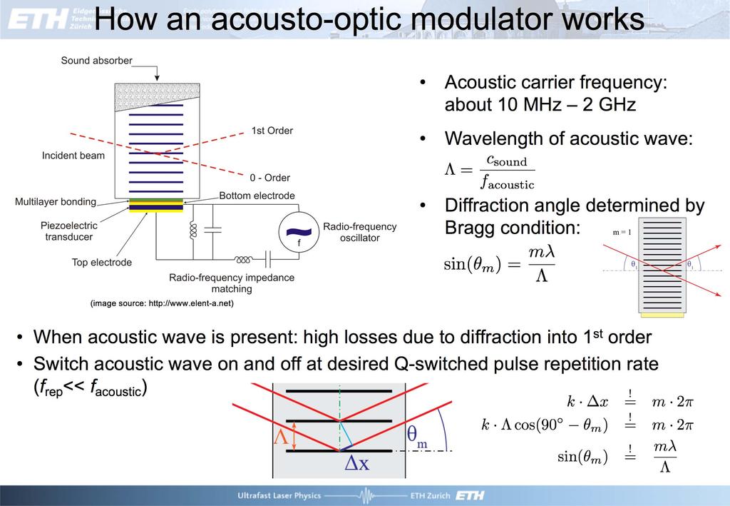
γ c = rl = lt R ~ e (g l)t/t R Intensität 0 e γ c t Zeit, ns
|
|
|
- Ἀελλώ Λαμπρόπουλος
- 8 χρόνια πριν
- Προβολές:
Transcript
1
2
3
4 There is however one main difference in this chapter compared to many other chapters. All loss and gain coefficients are given for the intensity and not the amplitude and are therefore a factor of 2 larger! l q q t o tal nonsaturable intensity loss coefficient per resonator round-trip (i.e. without the saturable absorber, but includes output coupler loss and any additional parasitic loss also the nonsaturable losses of the saturable absorber s a turable intensity loss coefficient of the saturable absorber per cavity round-trip u n bleached intensity loss coefficient of the saturable absorber per cavity roundtrip (i.e. maximum q at low intensity) g s a turated intensity gain coefficient per resonator round-trip (please note here we use intensity gain and not amplitude gain) g intensity small signal gain coefficient per resonator round-trip (often also simply called small signal gain). For a homogenous gain material applies in steady-state (factor 2 for a linear standing-wave resonator): g g = 1+ 2I I sat
5 g = rl γ c = lt R Intensität e γ c t ~ e (g l)t/t R ~ Zeit, ns
6 laser crystal A/O Q-switch output coupler diode laser focussing optics coating: HR - laser λ HT - diode λ acoustic transducer partially reflective coating
7
8
9
10
11
12 dn dt = KNn γ cn dn dt = R p γ L N KnN R p = P abs hν pump
13 dn dt = KNn γ c n dn dt = R p γ L N KnN dn dt 3τ L R p γ L N = R p N τ L () N t nt (), N max = R p τ L R p = const. N t ()= R p τ L 1 exp( t τ L ) ( ) = N max 1 exp t τ L τ L 2τ L t
14 3τ L nt (), R p = const. dn dt R p γ L N = R p N τ L () N t N max = R p τ L N t ()= R p τ L 1 exp( t τ L ) ( ) = N max 1 exp t τ L τ L 2τ L t E p = const. T rep > 3τ L, or f rep = 1 T rep < 1 3τ L 1 = 3τ L
15 dn dt = KNn γ c n dn dt = R p γ L N KnN N( t = )= N i nt= ( )= n i 1 dn dt K ( N i N th )n = KN th ( r 1)n = r 1 n τ c () n i exp r 1 nt τ c t τ c =T R l, g =rl = n i exp g l ( ) t T R N() t N i const. r = N i N th = γ c N th K
16 g = rl γ c = lt R Intensität e γ c t ~ e (g l)t/t R ~ Zeit, ns
17 n max dn dt = KNn γ c n N th = γ c K dn dt = R p γ L N KnN dn dn K ( N N th )n = N N th KnN N dn dt = K ( N N th )n dn KnN dt dn N th N N dn N( t = )= N i = rn th, n( t = )= n i 1 nt () n i dn Nt () N i =rn th N th N N dn nt () N i N() t N i r ln N i N t (), with N i = rn th nt ()= n max for g = l N()= t N th
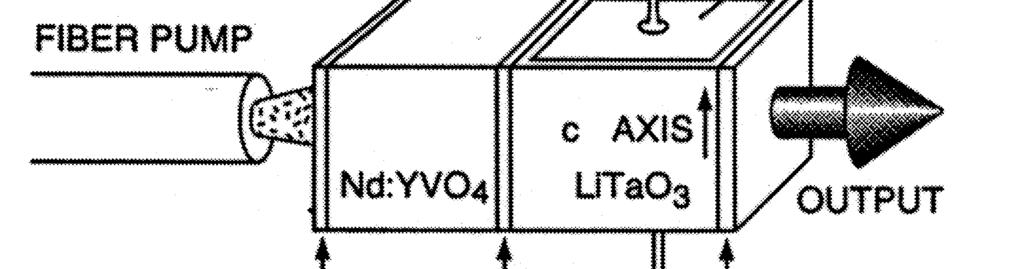
18 n max n max N i nt ()= n max for g = l N()= t N th n max r 1 lnr r N i, with N i = rn th P p,out = n maxhν τ c E p,out E p ( N i N f )hν
19 n max η Q - switched pulse energy stored energy ( = N i N f )hν = N i N f N i hν N i nt ()= n max for g = l N()= t N th n max r 1 lnr r N i, with N i = rn th P p,out = n maxhν τ c E p,out E p ( N i N f )hν E p,out = E p η( r)n i hν
20 n max τ p E p,out P p,out η( r)n i n max τ c rη ( r) r 1 ln r τ c τ p η( r) P p,out = n maxhν τ c τ c E p,out = E p η( r)n i hν
21 n max nt ()= n max exp( t τ c ) τ p η( r) P p,out = n maxhν τ c τ c E p,out = E p η( r)n i hν
22
23 dr di I > T R τ stim r T R τ L
24
25 Nd:LSB microchip laser (25% doped) A-FPSA Copper heat sink 1 % Output coupler 22 μm Cavity length 162 nm Pump 88 nm Waist radius: 4 μm Dichroic beamsplitter 88 nm 162 nm LT GaAs/InGaAs MQW absorber Sampling Oscilloscope 18 ps -5 5 Time [ps] GaAs Substrate GaAs/AlAs mirror Dielectric top mirror R t I in I out d
26 MISER: Monolithic Nd:YAG Laser Applying a magnetic field causes unidirectional lasing D C Evanescent wave coupled nonlinear semiconductor mirror Interface B (see Fig. 1a) Inside MISER (Nd:YAG, n =1.82) Air Inside nonlinear semiconductor mirror Saturable Absorber or Modulator section B z Mirror section A α > α Τ Pump-Laser: cw Ti:Sapphire 89 nm Output: Without nonlinear mirror -> cw output, single mode due to unidirectional ring laser With nonlinear mirror-> single mode Q-switched Airgap: Coupling through evanescent waves: Frustrated total internal reflection (FTIR)
27 μj-pulses with 1 khz repetition rates 1 mw average powers
28 Microchip crystal SESAM Output coupler Laser output Diode pump laser Copper heat sink Cavity length Dichroic beamsplitter pump wavelength laser wavelength
 1 top reflector HfO2/SiO2 τ A = 12 ps 2 15 Time delay pump-probe (ps) 4 3 2 1 incoming light Field intensity (rel. units) Field Intensity (Rel. Units) Reflectivity.96.92.")
29 absorber: InGaAs/GaAs quantum wells 1. substrate GaAs Refractive Index index Pump probe signal Bragg mirror AlAs/GaAs z (μm) 1 top reflector HfO2/SiO2 τ A = 12 ps 2 15 Time delay pump-probe (ps) incoming light Field intensity (rel. units) Field Intensity (Rel. Units) Reflectivity ΔR = 1.3% F sat 1 1 Fluence on absorber (μj/cm ) SESAM #1: R = 1.3% F sat = 36 μj/cm 2 Reflectivity ΔR = 7.3% F sat 1 1 Fluence on absorber (μj/cm ) SESAM #2: R = 7.3% F sat = 47 μj/cm 2
30 longitudinal section L g crosssection mode area A SESAM Gain R, F sat,a material Output coupler T out L, F sat,l Parasitic losses L p Total losses L tot = T out + L p out = L out /(L out + L p ) F sat,a << F sat,l = hν L 2σ L A > p
 t T R dt = gt () l () t qt () P() t dn L dt = N L τ L K L nn L + R p dg() t dt = gt () g τ L gt ()P() t E L dn A dt = N A N A τ A K A nn A dq() t dt =")
31 g q P - P + P + = - P = P T out n = P hν T R g = L g N L V σ L T R =2 Lc = 2L chν P V =A L L g = N L A L σ L q = N A A A σ A τ, E L L A L τ A, EA A A W stim = K L n = I hν σ L = P A L hν σ L K L = σ L A L T R dn dt = K L N L K A N A 1 τ c n dp () t T R dt = gt () l () t qt () P() t dn L dt = N L τ L K L nn L + R p dg() t dt = gt () g τ L gt ()P() t E L dn A dt = N A N A τ A K A nn A dq() t dt = qt () q τ A qt ()P() t E A
32 l +ΔR l l -ΔR Phase 1 Phase 2 Phase 3 Phase 4 Gain g(t) Loss q(t)+l E stored = E L g tot Time (ps) Intracavity power P(t) Δg T out + L p ΔR E released = E L Δg l l p q ΔR R): Δg 2ΔR
33 l +ΔR l l -ΔR Peak power (kw) Phase 1 Phase 2 Phase 3 Phase 4 Gain g(t) Loss q(t)+l Intracavity power P(t) Δg Time (ps) Unsaturated loss Gain g(t) r=3 Power P(t) 1 2 Time (μs) l + ΔR Gain g(t) r=2 No pulse for r= Gain, Loss (%)
")
34 E p hν L σ L E p A τ p 3.52T R ΔR A ΔR η out f rep g (L tot + ΔR) 2ΔRτ L L L + abs L
35

36 E stored = AL g N 2 hν L g = 2σ L N 2 L g E stored = hν L 2σ L Ag = E L g E released = E L Δg η out = Δg 2ΔR L out L out + L p E p hν L σ L AΔRη out
37 E p /E L (%) γ = L p = γδr γ =.2 γ =.4 L tot + ΔR = 2% γ =.6 L tot + ΔR =1% Gain reduction Δg (%) ΔR =15% ΔR =1% ΔR = 5% Total nonsaturable losses L tot (%) Total nonsaturable losses L tot (%) 25 R R L tot g 2 R
38 E p hν L σ L AΔRη out L L abs
 Δg τ p 3.")
39 l +ΔR l l -ΔR Phase 1 Phase 2 Phase 3 Phase 4 Gain g(t) Loss q(t)+l tot Intracavity power P(t) Δg τ p 3.52 T R q l q l < q Time (ps) g i l q q g f l q = q Δg q q / T R
40 τ p 3.52T R ΔR ps Time (ps) 2
41 L, R L, R P p ( ΔR) 2 P peak E p τ p L hν σ L AΔRη out 3.52T R ΔR ( ΔR)2 A η out T R σ L
42 P av = η s (P P P P,th ) f rep = P av E p = η s(p P P P,th ) E p r 1 P p P p,th E p r g l + q P P = P P,th = hν P A 2σ L τ L η P g hν P A ( l + q ) 2σ L τ L η P f rep = g (l + q ) Δgτ L g (l + q ) 2q τ L q ΔR
43 f rep g (L tot + ΔR) 2ΔRτ L g 2ΔRτ L L g f rep σ L g f rep
44 τ p 3.5T R ΔR 185 μm Nd:YVO Time (ps) 37 ps 2 f rep = 16 khz E p = 53 nj R 13 % p =37ps E p hν L σ L A ΔR η out 2 μm Yb:YAG* =1.3μm f rep = 12 khz E p = 1.1 μj p = 53 ps.5 mm Er:Yb:glass** = μm f rep = 1.4 khz E p = 11.2 μj p = 84 ps f rep g Different crystals and SESAMs Varying pump power 2ΔRτ L f rep = 32 Hz MHz
45 l + ΔR l l - ΔR Phase 1 Phase 2 Phase 3 Phase 4 Gain Loss Time (ps) Intracavity power E p hν L σ L 2F sat,l A ΔR η out τ p 3.5T R ΔR f rep g 2ΔRτ L g
 Pulse width (ps) Fluence (mj/cm 2 ) 25 T out = 4.8 % 2 15 T out = 9 % 1 5 5 4 T out = 9 % 3 2 1 T out = 4.8 % 6 T out = 9 % 4 2 T out = 4.")
46 Rep. rate (khz) Pulse width (ps) Fluence (mj/cm 2 ) R R 3 ΔR 7.3% 2 ΔR 1.3% 1 ΔR 7.3% 4 ΔR 1.3% 2 6 ΔR 1.3% 4 2 ΔR 7.3% Pump power (mw) Rep. rate (khz) Pulse width (ps) Fluence (mj/cm 2 ) 25 T out = 4.8 % 2 15 T out = 9 % T out = 9 % T out = 4.8 % 6 T out = 9 % 4 2 T out = 4.8 % Pump power (mw)
47 R Pulse width (ps) Fluence (mj/cm ) 2 Pulse energy (nj) Experiment Theory Theory Experiment linear fit without additive constant A (μm 2 )
48 Pulse width (ps) ΔR = 7.3% ΔR = 1.3% τ p 3.5T R ΔR Rep. rate (khz) 4 2 ΔR = 7.3% ΔR = 1.3% f rep g 2ΔRτ L Fluence (mj/cm 2 ) ΔR = 1.3% ΔR = 7.3% Pump power (mw) E p A hν L σ L ΔR η out
49 Pulse width (ns) SESAM Crystal Variable cavity length Output Coupler Output beam τ p 3.5T R ΔR R R Cavity length (mm)
50
51
52 Cross-section (x 1-2 cm 2 ) pumping emission absorption Wavelength (nm) 15 11

53 Pulse energy # : E p hν L σ L AΔRη out Pulse duration *# : τ 3.52T R p ΔR
54 2% Yb:YAG SEmiconductor Saturable Absorber Mirror SESAM 2 μm copper heat sink 4.8% output coupler 13 nm 968 nm 968 nm 13 nm Pump: 3 μm single emitter P pump,max = nm w px = 56 μm; w py = 27 μm substrate GaAs Refractive Index index absorber: 9 InGaAs/GaAs quantum wells Bragg mirror AlAs/GaAs 5 1 z (μm) z (μm) top reflector HfO2/SiO2 small penetration depth (a few μm) short pulses adjustable device parameters 15 incoming light Field Intensity intensity (Rel. Units) (rel. u.)
55 2. P pump = 485 mw Power (kw) Time (ps) 53 ps R 1.6% (R top = 75%) R ( R top ) R E p R top = % 3 mj/cm 2 R top = 75% 2 mj/cm 2 E p = 1.1 μj F p 1 mj/cm 2 p = 53 ps P peak = 2.1 kw P avg = 13.2 mw f rep = 12 khz
56 absorption length absorption bandwidth gain bandwidth Nd(3%):YVO 4 9 μm 1.5 nm 1 nm Nd(1.1%):YAG 12 μm.8 nm.5 nm Yb(2%):YAG 435 μm 2 nm 8.5 nm gain cross-section cm cm cm 2 typical pulse energies * typical pulse durations * 7 nj <1 ps 1 nj < 1 ns 1 μj < 1 ns good for single mode operation and short pulse generation good for large pulse energies
レーザ結晶. Altechna 社. Laser Crystals. Ti:Sapphire crystals. High damage threshold Strong Kerr effect
 Ti:Sapphire crystals Features Large gain-bandwidth Very large emission bandwidth Excellent thermal conductivity Short upper-state lifetime (3.2 μs) High saturation power Relatively high laser cross-sections
レーザ結晶. Altechna 社. Laser Crystals. Ti:Sapphire crystals. High damage threshold Strong Kerr effect
 Ti:Sapphire crystals Features Large gain-bandwidth Very large emission bandwidth Excellent thermal conductivity Short upper-state lifetime (3. μs) High saturation power Relatively high laser cross-sections
6.4 Superposition of Linear Plane Progressive Waves
 .0 - Marine Hydrodynamics, Spring 005 Lecture.0 - Marine Hydrodynamics Lecture 6.4 Superposition of Linear Plane Progressive Waves. Oblique Plane Waves z v k k k z v k = ( k, k z ) θ (Looking up the y-ais
 Problem 7.19 Ignoring reflection at the air soil boundary, if the amplitude of a 3-GHz incident wave is 10 V/m at the surface of a wet soil medium, at what depth will it be down to 1 mv/m? Wet soil is
Research on mode-locked optical fiber laser
 2003 6 20 Research on mode-locked optical fiber laser 1 36303 Abstract- For future ultrahigh-speed optical communications, an ultrashort optical pulse train at a high repetitionrate will be indispensable.
4.4 Superposition of Linear Plane Progressive Waves
 .0 Marine Hydrodynamics, Fall 08 Lecture 6 Copyright c 08 MIT - Department of Mechanical Engineering, All rights reserved..0 - Marine Hydrodynamics Lecture 6 4.4 Superposition of Linear Plane Progressive
the total number of electrons passing through the lamp.
 1. A 12 V 36 W lamp is lit to normal brightness using a 12 V car battery of negligible internal resistance. The lamp is switched on for one hour (3600 s). For the time of 1 hour, calculate (i) the energy
Thin Film Chip Resistors
 FEATURES PRECISE TOLERANCE AND TEMPERATURE COEFFICIENT EIA STANDARD CASE SIZES (0201 ~ 2512) LOW NOISE, THIN FILM (NiCr) CONSTRUCTION REFLOW SOLDERABLE (Pb FREE TERMINATION FINISH) Type Size EIA PowerRating
Contents 1. Introduction Theoretical Background Theoretical Analysis of Nonlinear Interactions... 35
 Contents 1. Introduction...1 1.1 Nonlinear Optics and Nonlinear-Optic Instruments...1 1.2 Waveguide and Integrated Optics...2 1.3. Historical Perspectives on Waveguide NLO Devices...3 1.4. Future Prospects...6
NPN SILICON OSCILLATOR AND MIXER TRANSISTOR
 FEATURES NPN SILICON OSCILLATOR AND MIXER TRANSISTOR LOW COST HIGH GAIN BANDWIDTH PRODUCT: ft = MHz TYP LOW COLLECTOR TO BASE TIME CONSTANT: CC r b'b = 5 ps TYP LOW FEEDBACK CAPACITANCE: CRE=.55 pf TYP
First Sensor Quad APD Data Sheet Part Description QA TO Order #
 Responsivity (/W) First Sensor Quad PD Data Sheet Features Description pplication Pulsed 16 nm laser detection RoHS 211/65/EU Light source positioning Laser alignment ø mm total active area Segmented in
Phys460.nb Solution for the t-dependent Schrodinger s equation How did we find the solution? (not required)
") Phys460.nb 81 ψ n (t) is still the (same) eigenstate of H But for tdependent H. The answer is NO. 5.5.5. Solution for the tdependent Schrodinger s equation If we assume that at time t 0, the electron starts
Phys460.nb 81 ψ n (t) is still the (same) eigenstate of H But for tdependent H. The answer is NO. 5.5.5. Solution for the tdependent Schrodinger s equation If we assume that at time t 0, the electron starts
Bulletin 1489 UL489 Circuit Breakers
 Bulletin 489 UL489 Circuit Breakers Tech Data 489-A Standard AC Circuit Breaker 489-D DC Circuit Breaker 489-A, AC Circuit Breakers 489-D, DC Circuit Breakers Bulletin 489-A Industrial Circuit Breaker
IXBH42N170 IXBT42N170
 High Voltage, High Gain BIMOSFET TM Monolithic Bipolar MOS Transistor IXBH42N17 IXBT42N17 S 9 = 1 = 42A (sat) 2.8V Symbol Test Conditions Maximum Ratings TO-247 (IXBH) S = 25 C to 15 C 17 V V CGR = 25
Monolithic Crystal Filters (M.C.F.)
") Monolithic Crystal Filters (M.C.F.) MCF (MONOLITHIC CRYSTAL FILTER) features high quality quartz resonators such as sharp cutoff characteristics, low loss, good inter-modulation and high stability over
Monolithic Crystal Filters (M.C.F.) MCF (MONOLITHIC CRYSTAL FILTER) features high quality quartz resonators such as sharp cutoff characteristics, low loss, good inter-modulation and high stability over
MAX4147ESD PART 14 SO TOP VIEW. Maxim Integrated Products 1 MAX4147 EVALUATION KIT AVAILABLE ; Rev 1; 11/96 V CC V EE OUT+ IN+ R t SENSE IN-
 -; Rev ; / EVALUATION KIT AVAILABLE µ µ PART ESD TEMP. RANGE - C to +5 C PPACKAGE SO TOP VIEW V EE V CC SENSE+ SENSE- R t R t R t R t MAX SENSE OUT SENSE+ SENSE- N.C. SHDN N.C. 3 5 R f R G R f 3 VDSL TRANSFORMER
wave energy Superposition of linear plane progressive waves Marine Hydrodynamics Lecture Oblique Plane Waves:
 3.0 Marine Hydrodynamics, Fall 004 Lecture 0 Copyriht c 004 MIT - Department of Ocean Enineerin, All rihts reserved. 3.0 - Marine Hydrodynamics Lecture 0 Free-surface waves: wave enery linear superposition,
What happens when two or more waves overlap in a certain region of space at the same time?
 Wave Superposition What happens when two or more waves overlap in a certain region of space at the same time? To find the resulting wave according to the principle of superposition we should sum the fields
Tunable Diode Lasers. Turning Laser Diodes into Diode Lasers. Mode selection. Laser diodes
 Tunable Diode Lasers Turning Laser Diodes into Diode Lasers Laser diodes Mode selection FP diodes high power at low cost AR diodes for best performance Compact and robust Littrow setup Highest power from
( ) Sine wave travelling to the right side
 Sine wave travelling to the right side") SOUND WAVES (1) Sound wave: Varia2on of density of air Change in density at posi2on x and 2me t: Δρ(x,t) = Δρ m sin kx ωt (2) Sound wave: Varia2on of pressure Bulk modulus B is defined as: B = V dp dv
SOUND WAVES (1) Sound wave: Varia2on of density of air Change in density at posi2on x and 2me t: Δρ(x,t) = Δρ m sin kx ωt (2) Sound wave: Varia2on of pressure Bulk modulus B is defined as: B = V dp dv
Surface Mount Multilayer Chip Capacitors for Commodity Solutions
 Surface Mount Multilayer Chip Capacitors for Commodity Solutions Below tables are test procedures and requirements unless specified in detail datasheet. 1) Visual and mechanical 2) Capacitance 3) Q/DF
(1) Describe the process by which mercury atoms become excited in a fluorescent tube (3)
 Describe the process by which mercury atoms become excited in a fluorescent tube (3)") Q1. (a) A fluorescent tube is filled with mercury vapour at low pressure. In order to emit electromagnetic radiation the mercury atoms must first be excited. (i) What is meant by an excited atom? (1) (ii)
Q1. (a) A fluorescent tube is filled with mercury vapour at low pressure. In order to emit electromagnetic radiation the mercury atoms must first be excited. (i) What is meant by an excited atom? (1) (ii)
65W PWM Output LED Driver. IDLV-65 series. File Name:IDLV-65-SPEC
 ~ A File Name:IDLV65SPEC 07050 SPECIFICATION MODEL OUTPUT OTHERS NOTE DC VOLTAGE RATED CURRENT RATED POWER DIMMING RANGE VOLTAGE TOLERANCE PWM FREQUENCY (Typ.) SETUP TIME Note. AUXILIARY DC OUTPUT Note.
X-Y COUPLING GENERATION WITH AC/PULSED SKEW QUADRUPOLE AND ITS APPLICATION
 X-Y COUPLING GENERATION WITH AC/PULSED SEW QUADRUPOLE AND ITS APPLICATION # Takeshi Nakamura # Japan Synchrotron Radiation Research Institute / SPring-8 Abstract The new method of x-y coupling generation
Positive dispersion: 2 n. ω > 0, 2 n. Negative dispersion: ω < 0, 2 n
 Positive dispersion: 2 n ω > 0, 2 n 2 λ > 0 2 Negative dispersion: 2 n ω < 0, 2 n 2 λ < 0 2 φ(z,ω) = k ( n ω )z E( z,t)= 1 2π E ( z = 0,ω )e iωt iφ z,ω e ( ) dω φ(z,ω) = k ( n ω )z φ( ω )= φ 0 + ω ω 0
ITU-R BT ITU-R BT ( ) ITU-T J.61 (
 ITU-T J.61 (") ITU-R BT.439- ITU-R BT.439- (26-2). ( ( ( ITU-T J.6 ( ITU-T J.6 ( ( 2 2 2 3 ITU-R BT.439-2 4 3 4 K : 5. ITU-R BT.24 :. ITU-T J.6. : T u ( ) () (S + L = M) :A :B :C : D :E :F :G :H :J :K :L :M :S :Tsy :Tlb
ITU-R BT.439- ITU-R BT.439- (26-2). ( ( ( ITU-T J.6 ( ITU-T J.6 ( ( 2 2 2 3 ITU-R BT.439-2 4 3 4 K : 5. ITU-R BT.24 :. ITU-T J.6. : T u ( ) () (S + L = M) :A :B :C : D :E :F :G :H :J :K :L :M :S :Tsy :Tlb
Matrices and Determinants
 Matrices and Determinants SUBJECTIVE PROBLEMS: Q 1. For what value of k do the following system of equations possess a non-trivial (i.e., not all zero) solution over the set of rationals Q? x + ky + 3z
555 TIMER APPLICATIONS AND VOLTAGE REGULATORS
 555 TIMER APPLICATIONS AND VOLTAGE REGULATORS OBJECTIVE The purpose of the experiment is to design and experimentally verify astable and monostable multivibrators using 555 timers; to design variable voltage
CMOS Technology for Computer Architects
 CMOS Technology for Computer Architects Iakovos Mavroidis Giorgos Passas Manolis Katevenis Lecture 13: On chip SRAM Technology FORTH ICS / EURECCA & UoC GREECE ABC A A E F A BCDAECF A AB C DE ABCDAECF
Thin Film Chip Resistors
 FETURES PRECISE TOLERNCE ND TEMPERTURE COEFFICIENT EI STNDRD CSE SIZES (0201 ~ 2512) LOW NOISE, THIN FILM (NiCr) CONSTRUCTION REFLOW SOLDERLE (Pb FREE TERMINTION FINISH) RoHS Compliant includes all homogeneous
DAMPING CROSS-REFERENCE
 AMPING CROSS-REFERENCE There are at least eleven parameters commonly used to express damping. Cross-reference formulas are given in Tables A through C. The formulas are taken from Reference. Let be the
PRELIMINARY DATA SHEET NPN EPITAXIAL SILICON TRANSISTOR FOR MICROWAVE HIGH-GAIN AMPLIFICATION
 PRELIMINARY DATA SHEET NPN EPITAXIAL SILICON TRANSISTOR FOR MICROWAVE HIGH-GAIN AMPLIFICATION NE699M FEATURES OUTLINE DIMENSIONS (Units in mm) HIGH ft: 6 GHz TYP at V, ma LOW NOISE FIGURE: NF =. db TYP
SUPPLEMENTARY INFORMATION
 Sensitivity of [Ru(phen) 2 dppz] 2+ Light Switch Emission to Ionic Strength, Temperature, and DNA Sequence and Conformation Andrew W. McKinley, Per Lincoln and Eimer M. Tuite* SUPPLEMENTARY INFORMATION
Applications. 100GΩ or 1000MΩ μf whichever is less. Rated Voltage Rated Voltage Rated Voltage
 Features Rated Voltage: 100 VAC, 4000VDC Chip Size:,,,,, 2220, 2225 Electrical Dielectric Code EIA IEC COG 1BCG Applications Modems LAN / WAN Interface Industrial Controls Power Supply Back-Lighting Inverter
38 Te(OH) 6 2NH 4 H 2 PO 4 (NH 4 ) 2 HPO 4
 6 2NH 4 H 2 PO 4 (NH 4 ) 2 HPO 4") Fig. A-1-1. Te(OH) NH H PO (NH ) HPO (TAAP). Projection of the crystal structure along the b direction [Ave]. 9 1. 7.5 ( a a )/ a [1 ] ( b b )/ b [1 ] 5..5 1.5 1 1.5 ( c c )/ c [1 ].5 1. 1.5. Angle β 1.
Fig. A-1-1. Te(OH) NH H PO (NH ) HPO (TAAP). Projection of the crystal structure along the b direction [Ave]. 9 1. 7.5 ( a a )/ a [1 ] ( b b )/ b [1 ] 5..5 1.5 1 1.5 ( c c )/ c [1 ].5 1. 1.5. Angle β 1.
Magnetically Coupled Circuits
 DR. GYURCSEK ISTVÁN Magnetically Coupled Circuits Sources and additional materials (recommended) Dr. Gyurcsek Dr. Elmer: Theories in Electric Circuits, GlobeEdit, 2016, ISBN:978-3-330-71341-3 Ch. Alexander,
AT Surface Mount Package SOT-363 (SC-70) I I Y. Pin Connections B 1 C 1 E 1 E 2 C 2 B , 7:56 PM
 I I Y. Pin Connections B 1 C 1 E 1 E 2 C 2 B , 7:56 PM") AT-3263 Surface Mount Package SOT-363 (SC-7) I I Y Pin Connections B 1 C 1 E 1 E 2 C 2 B 2 Page 1 21.4., 7:6 PM Absolute Maximum Ratings [1] Absolute Thermal Resistance [2] : Symbol Parameter Units Maximum
AT-3263 Surface Mount Package SOT-363 (SC-7) I I Y Pin Connections B 1 C 1 E 1 E 2 C 2 B 2 Page 1 21.4., 7:6 PM Absolute Maximum Ratings [1] Absolute Thermal Resistance [2] : Symbol Parameter Units Maximum
Electrical Specifications at T AMB =25 C DC VOLTS (V) MAXIMUM POWER (dbm) DYNAMIC RANGE IP3 (dbm) (db) Output (1 db Comp.) at 2 f U. Typ.
 MAXIMUM POWER (dbm) DYNAMIC RANGE IP3 (dbm) (db) Output (1 db Comp.) at 2 f U. Typ.") Surface Mount Monolithic Amplifiers High Directivity, 50Ω, 0.5 to 5.9 GHz Features 3V & 5V operation micro-miniature size.1"x.1" no external biasing circuit required internal DC blocking at RF input &
Surface Mount Monolithic Amplifiers High Directivity, 50Ω, 0.5 to 5.9 GHz Features 3V & 5V operation micro-miniature size.1"x.1" no external biasing circuit required internal DC blocking at RF input &
SAW FILTER - RF RF SAW FILTER
 FEATURES - Frequencies from 0MHz to 700MHz - Custom specifications available - Industry standard package configurations - Low-loss saw component - Low amplitude ripple - RoHS compliance - Electrostatic
2. Laser Specifications 2 1 Specifications IK4301R D IK4401R D IK4601R E IK4101R F. Linear Linear Linear Linear
 2. Laser Specifications 2 1 Specifications IK4301R D IK4401R D IK4601R E IK4101R F 441.6 441.6 441.6 441.6 30 50 70 100 TEM00 TEM00 TEM00 TEM00 BEAM DIAMETER ( 1/e2) 1.1 1.1 1.2 1.2 0.5 0.5 0.5 0.4 RATIO
6.1. Dirac Equation. Hamiltonian. Dirac Eq.
 6.1. Dirac Equation Ref: M.Kaku, Quantum Field Theory, Oxford Univ Press (1993) η μν = η μν = diag(1, -1, -1, -1) p 0 = p 0 p = p i = -p i p μ p μ = p 0 p 0 + p i p i = E c 2 - p 2 = (m c) 2 H = c p 2
Gearmotor Data. SERIES GM9000: We have the GM9434H187-R1
 SERIES GM9: We have the GM9434H187-R1 Gearmotor Data Item Parameter Symbol Units 5.9:1 11.5:1 19.7:1 38.3:1 65.5:1 127.8:1 218.4:1 425.9:1 728.1:1 1419.8:1 2426.9:1 4732.5:1 1 Max. Load Standard Gears
Precision Metal Film Fixed Resistor Axial Leaded
 Features EIA standard colour-coding Non-Flame type available Low noise and voltage coefficient Low temperature coefficient range Wide precision range in small package Too low or too high ohmic value can
3 V, 1500 MHz Si MMIC WIDEBAND AMPLIFIER
 V, MHz Si MMIC WIDEBAND AMPLIFIER UPC7T FEATURES WIDE FREQUENCY RESPONSE: MHz LOW VOLTAGE OPERATION: V NOMINAL (. MIN) LOW POWER CONSUMPTION:. mw TYP SUPER SMALL PACKAGE TAPE AND REEL PACKAGING OPTION
65W PWM Output LED Driver. IDPV-65 series. File Name:IDPV-65-SPEC
 IDPV65 series ~ A File Name:IDPV65SPEC 07060 IDPV65 series SPECIFICATION MODEL OUTPUT OTHERS NOTE DC VOLTAGE RATED CURRENT RATED POWER DIMMING RANGE VOLTAGE TOLERANCE PWM FREQUENCY (Typ.) SETUP TIME Note.
TRC ELECTRONICS, INC LED Driver Constant Voltage 45W MEAN WELL IDLV-45 Series
 LED Driver Constant Voltage 5W MEAN WELL IDLV5 Series ~ A File Name:IDLV5SPEC 0707 TRC ELECTRONICS, INC..888.6.95 LED Driver Constant Voltage 5W MEAN WELL IDLV5 Series TRC ELECTRONICS, INC. SPECIFICATION
IDPV-45 series. 45W PWM Output LED Driver. File Name:IDPV-45-SPEC S&E
 IDPV5 series S&E ~ A File Name:IDPV5SPEC 0805 IDPV5 series SPECIFICATION MODEL OUTPUT INPUT OTHERS NOTE DC VOLTAGE RATED CURRENT RATED POWER DIMMING RANGE VOLTAGE TOLERANCE PWM FREQUENCY (Typ.) SETUP TIME
Areas and Lengths in Polar Coordinates
 Kiryl Tsishchanka Areas and Lengths in Polar Coordinates In this section we develop the formula for the area of a region whose boundary is given by a polar equation. We need to use the formula for the
Volume of a Cuboid. Volume = length x breadth x height. V = l x b x h. The formula for the volume of a cuboid is
 Volume of a Cuboid The formula for the volume of a cuboid is Volume = length x breadth x height V = l x b x h Example Work out the volume of this cuboid 10 cm 15 cm V = l x b x h V = 15 x 6 x 10 V = 900cm³
Areas and Lengths in Polar Coordinates
 Kiryl Tsishchanka Areas and Lengths in Polar Coordinates In this section we develop the formula for the area of a region whose boundary is given by a polar equation. We need to use the formula for the
Thin Film Chip Resistors
 FETURES PRECISE TOLERNCE ND TEMPERTURE COEFFICIENT EI STNDRD CSE SIZES (0201 ~ 2512) LOW NOISE, THIN FILM (NiCr) CONSTRUCTION REFLOW SOLDERLE (Pb FREE TERMINTION FINISH) Type EI Size Power Rating at 70
IDPV-25 series. 25W PWM Output LED Driver. File Name:IDPV-25-SPEC S&E
 5W PWM Output LED Driver IDPV5 series S&E ~ A File Name:IDPV5SPEC 0805 5W PWM Output LED Driver IDPV5 series SPECIFICATION MODEL IDPV5 IDPV5 4 IDPV5 6 IDPV5 48 IDPV5 60 DC VOLTAGE V 4V 6V 48V 60V CONSTANT
For a wave characterized by the electric field
 Problem 7.9 For a wave characterized by the electric field E(z,t) = ˆxa x cos(ωt kz)+ŷa y cos(ωt kz+δ) identify the polarization state, determine the polarization angles (γ, χ), and sketch the locus of
Main source: "Discrete-time systems and computer control" by Α. ΣΚΟΔΡΑΣ ΨΗΦΙΑΚΟΣ ΕΛΕΓΧΟΣ ΔΙΑΛΕΞΗ 4 ΔΙΑΦΑΝΕΙΑ 1
 Main source: "Discrete-time systems and computer control" by Α. ΣΚΟΔΡΑΣ ΨΗΦΙΑΚΟΣ ΕΛΕΓΧΟΣ ΔΙΑΛΕΞΗ 4 ΔΙΑΦΑΝΕΙΑ 1 A Brief History of Sampling Research 1915 - Edmund Taylor Whittaker (1873-1956) devised a
Technical Report. General Design Data of a Three Phase Induction Machine 90kW Squirrel Cage Rotor
 Technical Report General Design Data of a Three Phase Induction Machine 90kW Squirrel Cage Rotor Tasos Lazaridis Electrical Engineer CAD/CAE Engineer tasoslazaridis13@gmail.com Three-Phase Induction Machine
3 V, 900 MHz Si MMIC AMPLIFIER
 V, 9 MHz Si MMIC AMPLIFIER UPC77T FEATURES LOW VOLTAGE - LOW CURRENT: ma at V LOW POWER CONSUMPTION: mw TYP SUPER SMALL PACKAGE TAPE AND REEL PACKAGING OPTION AVAILABLE DESCRIPTION The UPC77T is a Silicon
Solutions to the Schrodinger equation atomic orbitals. Ψ 1 s Ψ 2 s Ψ 2 px Ψ 2 py Ψ 2 pz
 Solutions to the Schrodinger equation atomic orbitals Ψ 1 s Ψ 2 s Ψ 2 px Ψ 2 py Ψ 2 pz ybridization Valence Bond Approach to bonding sp 3 (Ψ 2 s + Ψ 2 px + Ψ 2 py + Ψ 2 pz) sp 2 (Ψ 2 s + Ψ 2 px + Ψ 2 py)
Mock Exam 7. 1 Hong Kong Educational Publishing Company. Section A 1. Reference: HKDSE Math M Q2 (a) (1 + kx) n 1M + 1A = (1) =
 (1 + kx) n 1M + 1A = (1) =") Mock Eam 7 Mock Eam 7 Section A. Reference: HKDSE Math M 0 Q (a) ( + k) n nn ( )( k) + nk ( ) + + nn ( ) k + nk + + + A nk... () nn ( ) k... () From (), k...() n Substituting () into (), nn ( ) n 76n 76n
Mock Eam 7 Mock Eam 7 Section A. Reference: HKDSE Math M 0 Q (a) ( + k) n nn ( )( k) + nk ( ) + + nn ( ) k + nk + + + A nk... () nn ( ) k... () From (), k...() n Substituting () into (), nn ( ) n 76n 76n
Data sheet Thick Film Chip Resistor 5% - RS Series 0201/0402/0603/0805/1206
 Data sheet Thick Film Chip Resistor 5% - RS Series 0201/0402/0603/0805/1206 Scope -This specification applies to all sizes of rectangular-type fixed chip resistors with Ruthenium-base as material. Features
Multilayer Ceramic Chip Capacitors
 FEATURES X7R, X6S, X5R AND Y5V DIELECTRICS HIGH CAPACITANCE DENSITY ULTRA LOW ESR & ESL EXCELLENT MECHANICAL STRENGTH NICKEL BARRIER TERMINATIONS RoHS COMPLIANT SAC SOLDER COMPATIBLE* Temperature Coefficient
2.5 GHz SILICON MMIC WIDE-BAND AMPLIFIER
 . GHz SILICON MMIC WIDE-BAND AMPLIFIER UPC79T FEATURES WIDE FREQUENCY RESPONSE:. GHz 3 GAIN vs. FREQUENCY HIGH GAIN: 3 db (UPC79T) SATURATED OUTPUT POWER: +. dbm (UPC79T) INTERNAL CURRENT REGULATION MINIMIZES
Capacitors - Capacitance, Charge and Potential Difference
 Capacitors - Capacitance, Charge and Potential Difference Capacitors store electric charge. This ability to store electric charge is known as capacitance. A simple capacitor consists of 2 parallel metal
SMD Transient Voltage Suppressors
 SMD Transient Suppressors Feature Full range from 0 to 22 series. form 4 to 60V RMS ; 5.5 to 85Vdc High surge current ability Bidirectional clamping, high energy Fast response time
RECIPROCATING COMPRESSOR CALCULATION SHEET
 Gas properties, flowrate and conditions 1 Gas name Air RECIPRCATING CMPRESSR CALCULATIN SHEET WITH INTERCLER ( Sheet : 1. f 4.) Item or symbol Quantity Unit Item or symbol Quantity Unit 2 Suction pressure,
DC-DC Constant Current Step-Down LED driver LDD-300L LDD-350L LDD-500L LDD-600L LDD-700L CURRENT RANGE
 SPECIFICATION ORDER NO. LDD-00L LDD-0L LDD-00L LDD-00L LDD-700L CURRENT RANGE 00mA 0mA 00mA VOLTAGE RANGE Note. ~ VDC for LDD-00~700L/LW ; ~ 8VDC for LDD-00~700LS CURRENT ACCURACY (Typ.) ±% at VDC input
CT Correlation (2B) Young Won Lim 8/15/14
 Young Won Lim 8/15/14") CT Correlation (2B) 8/5/4 Copyright (c) 2-24 Young W. Lim. Permission is granted to copy, distribute and/or modify this document under the terms of the GNU Free Documentation License, Version.2 or any
CT Correlation (2B) 8/5/4 Copyright (c) 2-24 Young W. Lim. Permission is granted to copy, distribute and/or modify this document under the terms of the GNU Free Documentation License, Version.2 or any
Supporting Information
 Supporting Information On the Ambiguity of 1,3,2-Benzodiazaboroles as Donor/Acceptor unctionalities in Luminescent Molecules Lothar Weber *[a], Johannes Halama [a], Kenny Hanke [a], Lena Böhling [a], Andreas
3 V, 900 MHz LOW NOISE SI MMIC AMPLIFIER
 V, 9 MHz LOW NOISE SI MMIC AMPLIFIER UPC78T FEATURES.8 db NOISE FIGURE LOW VOLTAGE - LOW CURRENT: ma at V LOW POWER CONSUMPTION: 8 mw TYP SUPER SMALL PACKAGE TAPE AND REEL PACKAGING OPTION AVAILABLE DESCRIPTION
Derivation of Optical-Bloch Equations
 Appendix C Derivation of Optical-Bloch Equations In this appendix the optical-bloch equations that give the populations and coherences for an idealized three-level Λ system, Fig. 3. on page 47, will be
PPA Metallized polypropylene film capacitor MKP - Snubber/pulse - High current
 Main applications Snubber capacitor for energy conversion and control in power semiconductor circuits, protection circuits in SMPSs, induction heaters, high voltage, high current and high pulse applications
B37631 K K 0 60
 Multilayer Ceramic acitors High; X5R and X7R Chip Ordering code system B37631 K 7 5 K 6 Packaging 6 ^ cardboard tape, 18-mm reel 62 ^ blister tape, 18-mm reel Internal coding acitance tolerance K ^ ± %
NTC thermistors for temperature measurement
 NTC thermistors for temperature measurement SMD NTC thermistors with nickel barrier termination, case size 0603 Series/Type: Date: June 2008 EPCOS AG 2008. Reproduction, publication and dissemination of
Multilayer Ceramic Chip Capacitors
 FEATURES X7R, X6S, X5R AND Y5V DIELECTRICS HIGH CAPACITANCE DENSITY ULTRA LOW ESR & ESL EXCELLENT MECHANICAL STRENGTH NICKEL BARRIER TERMINATIONS RoHS COMPLIANT SAC SOLDER COMPATIBLE* PART NUMBER SYSTEM
Characterization Report
 Characterization Report RF Coaxial Cable Assemblies Raw Cable Type: Temp-Flex 047-2801 RF047-11SP9-11SP9-0305 Test Date: 10 Dec. 2014 RF047-11RP9-11RP9-0305 Test Date: 13 Oct. 2014 RF047-01SP1-01SP1-0305
Rating to Unit ma ma mw W C C. Unit Forward voltage Zener voltage. Condition
 MA MA Series Silicon planer e For stabilization of power supply ø.56. Unit : mm Features Color indication of VZ rank classification High reliability because of combination of a planer chip and glass seal
FDL - FXDL FBDL SERIES
 FDL - FXDL FBDL SERIES SUBMERSIBLE PUMPS FOR WITH ENTRAINED SOLIDS WASTE WATER Sewage pumps with power up to 22 kw (30 HP). Available in cast iron (FDL), AISI 316 stainless steel (FXDL), B10 bronze (FBDL).
RSDW08 & RDDW08 series
 /,, MODEL SELECTION TABLE INPUT ORDER NO. INPUT VOLTAGE (RANGE) NO LOAD INPUT CURRENT FULL LOAD VOLTAGE CURRENT EFFICIENCY (Typ.) CAPACITOR LOAD (MAX.) RSDW08F-03 344mA 3.3V 2000mA 80% 2000μF RSDW08F-05
Transient Voltage Suppressor
 Transient Suppressor Features Glass passivated junction Low incremental surge resistance, excellent clamping capability Underwriters Laboratory Recognition under UL standard for safety 497B: Isolated Loop
ΙΕΥΘΥΝΤΗΣ: Καθηγητής Γ. ΧΡΥΣΟΛΟΥΡΗΣ Ι ΑΚΤΟΡΙΚΗ ΙΑΤΡΙΒΗ
 ΠΑΝΕΠΙΣΤΗΜΙΟ ΠΑΤΡΩΝ ΠΟΛΥΤΕΧΝΙΚΗ ΣΧΟΛΗ ΤΜΗΜΑ ΜΗΧΑΝΟΛΟΓΩΝ ΚΑΙ ΑΕΡΟΝΑΥΠΗΓΩΝ ΜΗΧΑΝΙΚΩΝ ΕΡΓΑΣΤΗΡΙΟ ΣΥΣΤΗΜΑΤΩΝ ΠΑΡΑΓΩΓΗΣ & ΑΥΤΟΜΑΤΙΣΜΟΥ / ΥΝΑΜΙΚΗΣ & ΘΕΩΡΙΑΣ ΜΗΧΑΝΩΝ ΙΕΥΘΥΝΤΗΣ: Καθηγητής Γ. ΧΡΥΣΟΛΟΥΡΗΣ Ι ΑΚΤΟΡΙΚΗ
LIGHT UNFLAVORED MESONS (S = C = B = 0)
") LIGHT UNFLAVORED MESONS (S = C = B = 0) For I = 1 (π, b, ρ, a): ud, (uu dd)/ 2, du; for I = 0 (η, η, h, h, ω, φ, f, f ): c 1 (uu + d d) + c 2 (s s) π ± I G (J P ) = 1 (0 ) Mass m = 139.57018 ± 0.00035
LIGHT UNFLAVORED MESONS (S = C = B = 0) For I = 1 (π, b, ρ, a): ud, (uu dd)/ 2, du; for I = 0 (η, η, h, h, ω, φ, f, f ): c 1 (uu + d d) + c 2 (s s) π ± I G (J P ) = 1 (0 ) Mass m = 139.57018 ± 0.00035
 μ μ μ s t j2 fct T () = a() t e π s t ka t e e j2π fct j2π fcτ0 R() = ( τ0) xt () = α 0 dl () pt ( lt) + wt () l wt () N 2 (0, σ ) Time-Delay Estimation Bias / T c 0.4 0.3 0.2 0.1 0-0.1-0.2-0.3 In-phase
Section 8.3 Trigonometric Equations
 99 Section 8. Trigonometric Equations Objective 1: Solve Equations Involving One Trigonometric Function. In this section and the next, we will exple how to solving equations involving trigonometric functions.
Απόκριση σε Μοναδιαία Ωστική Δύναμη (Unit Impulse) Απόκριση σε Δυνάμεις Αυθαίρετα Μεταβαλλόμενες με το Χρόνο. Απόστολος Σ.
 Απόκριση σε Δυνάμεις Αυθαίρετα Μεταβαλλόμενες με το Χρόνο. Απόστολος Σ.") Απόκριση σε Δυνάμεις Αυθαίρετα Μεταβαλλόμενες με το Χρόνο The time integral of a force is referred to as impulse, is determined by and is obtained from: Newton s 2 nd Law of motion states that the action
Απόκριση σε Δυνάμεις Αυθαίρετα Μεταβαλλόμενες με το Χρόνο The time integral of a force is referred to as impulse, is determined by and is obtained from: Newton s 2 nd Law of motion states that the action
NPN Silicon RF Transistor BFQ 74
 NPN Silicon RF Transistor BFQ 74 For low-noise amplifiers in the GHz range, and broadband analog and digital applications in telecommunications systems at collector currents from 1 ma to 25 ma. Hermetically
Probability and Random Processes (Part II)
") Probability and Random Processes (Part II) 1. If the variance σ x of d(n) = x(n) x(n 1) is one-tenth the variance σ x of a stationary zero-mean discrete-time signal x(n), then the normalized autocorrelation
Probability and Random Processes (Part II) 1. If the variance σ x of d(n) = x(n) x(n 1) is one-tenth the variance σ x of a stationary zero-mean discrete-time signal x(n), then the normalized autocorrelation
Math221: HW# 1 solutions
 Math: HW# solutions Andy Royston October, 5 7.5.7, 3 rd Ed. We have a n = b n = a = fxdx = xdx =, x cos nxdx = x sin nx n sin nxdx n = cos nx n = n n, x sin nxdx = x cos nx n + cos nxdx n cos n = + sin
1000 VDC 1250 VDC 125 VAC 250 VAC J K 125 VAC, 250 VAC
 Metallized Polyester Film Capacitor Type: ECQE(F) Non-inductive construction using metallized Polyester film with flame retardant epoxy resin coating Features Self-healing property Excellent electrical
GenX3 TM 300V IGBT IXGA42N30C3 IXGH42N30C3 IXGP42N30C3 V CES = 300V I C110. = 42A V CE(sat) 1.85V t fi typ. = 65ns
 1.85V t fi typ. = 65ns") GenX3 TM V IGBT High Speed PT IGBTs for -1kHz switching IXGA42NC3 IXGH42NC3 IXGP42NC3 V CES = V 1 = 42A V CE(sat) 5V t fi typ = 65ns TO-263 (IXGA) Symbol Test Conditions Maximum Ratings V CES = 25 C to
GenX3 TM V IGBT High Speed PT IGBTs for -1kHz switching IXGA42NC3 IXGH42NC3 IXGP42NC3 V CES = V 1 = 42A V CE(sat) 5V t fi typ = 65ns TO-263 (IXGA) Symbol Test Conditions Maximum Ratings V CES = 25 C to
Metal Oxide Varistors (MOV) Data Sheet
 Data Sheet") Φ SERIES Metal Oxide Varistors (MOV) Data Sheet Features Wide operating voltage (V ma ) range from 8V to 0V Fast responding to transient over-voltage Large absorbing transient energy capability Low clamping
Φ SERIES Metal Oxide Varistors (MOV) Data Sheet Features Wide operating voltage (V ma ) range from 8V to 0V Fast responding to transient over-voltage Large absorbing transient energy capability Low clamping
IXBK64N250 IXBX64N250
 High Voltage, High Gain BiMOSFET TM Monolithic Bipolar MOS Transistor IXBK64N25 IXBX64N25 V CES = 25V 11 = 64A V CE(sat) 3.V TO-264 (IXBK) Symbol Test Conditions Maximum Ratings V CES = 25 C to 15 C 25
Calculating the propagation delay of coaxial cable
 Your source for quality GNSS Networking Solutions and Design Services! Page 1 of 5 Calculating the propagation delay of coaxial cable The delay of a cable or velocity factor is determined by the dielectric
C4C-C4H-C4G-C4M MKP Series AXIAL CAPACITORS PCB APPLICATIONS
 C4C-C4H-C4G-C4M AXIAL CAPACITORS PCB APPLICATIONS General characteristics - Self-Healing - Low losses - High ripple current - High contact reliability - Suitable for high frequency applications 40 ±5 L
[1] P Q. Fig. 3.1
![[1] P Q. Fig. 3.1](/thumbs/79/80362156.jpg "[1] P Q. Fig. 3.1") 1 (a) Define resistance....... [1] (b) The smallest conductor within a computer processing chip can be represented as a rectangular block that is one atom high, four atoms wide and twenty atoms long. One
1 (a) Define resistance....... [1] (b) The smallest conductor within a computer processing chip can be represented as a rectangular block that is one atom high, four atoms wide and twenty atoms long. One
NKT NTC Thermistor. Negative Temperature Coefficient Thermistor FEATURES
 FEATURES Large, strong capacity of suppression of inrush current Big material (B value), small residual Small size, Long life, high reliability and fast response APPLICATIONS Switching -supply, switch,
 Distributed by: www.jameco.com -800-83-4242 The content and copyrights of the attached material are the property of its owner. Single-Chip Voice Record/Playback Devices 60-, 75-, 90-, and 20-Second Durations
Advanced operation schemes: two-color, split & delay
 Advanced operation schemes: two-color, split & delay Production of two FEL pulses of different wavelengths with a controllable temporal delay (and) Splitting the FEL pulse into two sequential pulses at
ΗΛΕΚΤΡΟ-ΟΠΤΙΚΗ & ΕΦΑΡΜΟΓΕΣ
 12/10/2016 ΗΛΕΚΤΡΟ-ΟΠΤΙΚΗ & ΕΦΑΡΜΟΓΕΣ Χειμερινό Εξάμηνο 2016-2017 Γενικές Πληροφορίες Ώρα: Πέμπτη 09:00-11:45 Αίθουσα: Αιθ. 103 (Νέα Κτίρια ΗΜΜΥ) Καθηγητής: Ηλίας Ν. Γλύτσης Γραφείο: 2.2.22 Τηλέφωνο: 210-772-2479
Three coupled amplitudes for the πη, K K and πη channels without data
 Three coupled amplitudes for the πη, K K and πη channels without data Robert Kamiński IFJ PAN, Kraków and Łukasz Bibrzycki Pedagogical University, Kraków HaSpect meeting, Kraków, V/VI 216 Present status
TUBO LED T8 LLUMOR PROLED 18W 120CM
 Luminaire Property Luminaire: Report NO.: Test NO.: Lamp: LLUMOR-PL-T8-18W 6000K Sum Lumens: 2483.33 lm Number of Lamps: 1 Diameter: 0mm Length: 1200mm Photometric Type: Type C Photometric Results Voltage:
SOFT FERRITE CORE FOR EMI/EMC SUPPRESSION. AVERTEC Co., Ltd.
 - 0 - SOFT FERRITE ORE FOR EMI/EM SUPPRESSION RM423, Ilsan Techno Town, 38, Ilsan-ro, Ilsandong-gu, Goyang-si, Gyeonggi-do, 40-722, Korea Tel. (070)4632-5555~6 Fax. (070)4032-5555 http://www.avertec.kr