IAN MITRE SAW PKS 1500 A2. ΦΑΛΤΣΟΠΡΙΟΝΟ Οδηγίες χειρισμού και ασφαλείας Μετάφραση του πρωτοτύπου των οδηγιών χρήσης
|
|
|
- Φιλομήλα Κυπραίος
- 6 χρόνια πριν
- Προβολές:
Transcript


1 MITRE SAW PKS 1500 A2 GB IE NI MITRE SAW Operating and Safety Instructions Translation of Original Operating Manual GR CY ΦΑΛΤΣΟΠΡΙΟΝΟ Οδηγίες χειρισμού και ασφαλείας Μετάφραση του πρωτοτύπου των οδηγιών χρήσης DK AFKORTER- EG GERINGSSAV Brugs- og sikkerhedsanvisninger Oversættelse af den originale driftsvejledning FR BE SCIE DE COUPE ET A ONGLET Consignes d utilisation et de sécurité Traduction du manuel d origine NL BE AFKORT- EN VERSTEKZAAG Gebruiks- en veiligheidsvoorschriften Vertaling van de originele gebruikshandleiding DE AT CH KAPP- UND GEHRUNGSSÄGE Bedienungs- und Sicherheitshinweise Originalbetriebsanleitung IAN GB DK IE BE NI NL
2 GB IE NI Before reading, unfold the page containing the illustrations and familiarise yourself with all functions of the device. GR CY Πριν ξεκινήσετε την ανάγνωση, ανοίξτε τη σελίδα με τις εικόνες και εξοικειωθείτε με όλες τις λειτουργίες της συσκευής. DK Før du læser, vend begge sidene med billeder frem og bliv bekendt med alle apparatets funktioner. FR BE Avant de lire le mode d emploi, ouvrez la page contenant les illustrations et familiarisez-vous ensuite avec toutes les fonctions de l appareil. NL BE Vouw vóór het lezen de pagina met de afbeeldingen open en maak u vertrouwd met alle functies van het apparaat. DE AT CH Klappen Sie vor dem Lesen die Seite mit den Abbildungen aus und machen Sie sich anschließend mit allen Funktionen des Gerätes vertraut. GB / IE / NI Operation and Safety Notes Page 01 GR / CY Οδηγίες χειρισμού και ασφαλείας Σελίδα 12 DK Brugs- og sikkerhedsanvisninger Side 25 FR / BE Instructions d utilisation et consignes de sécurité Page 36 NL / BE Bedienings- en veiligheidsinstructies Pagina 49 DE / AT / CH Bedienungs- und Sicherheitshinweise Seite 60
3 GB IE NI Read and follow the operating and safety instructions before you start working with this power tool! GR CY Πριν θέσετε τη συσκευή σε λειτουργία, διαβάστε και τηρείτε τις οδηγίες χειρισμού και τις υποδείξεις ασφαλείας! DK IE Før start drifts- og sikkerhedsinstruktioner, læse og observere! FR BE Avant la mise en service, lisez le mode d emploi et les consignes de sécurité et respectez-les! NL BE Vóór ingebruikneming de handleiding en de veiligheidsvoorschriften lezen en in acht nemen! DE AT CH Vor Inbetriebnahme Bedienungsanleitung und Sicherheitshinweise lesen und beachten! GB IE NI Wear safety goggles! GR CY Να φοράτε προστατευτικά γυαλιά! DK IE Brug sikkerhedsbriller! FR BE Portez des lunettes de protection! NL BE Draag een veiligheidsbril! DE AT CH Schutzbrille tragen! GB IE NI Wear ear-muffs! GR CY Να φοράτε προστασία ακοής! DK IE Brug høreværn! FR BE Porter une protection de l ouïe! NL BE Gehoorbeschermer dragen! DE AT CH Gehörschutz tragen! GB IE NI Wear a breathing mask! GR CY Σε περίπτωση εκπομπής σκόνης, να φοράτε προστασία αναπνοής! DK IE Brug støvmaske! FR BE En cas de dégagement de poussière! NL BE Bij het vrijkomen van stof! DE AT CH Bei Staubentwicklung Atemschutz tragen! GB IE NI Important! Risk of injury! Never reach into the running saw blade! GR CY Προσοχή! Κίνδυνος τραυματισμού! Μην τοποθετείτε τα χέρια σας στην περιοχή της κινούμενης λάμας πριονιού! DK IE Vigtigt! Fare for kvæstelse! Hold hænderne borte fra den roterende savklinge! FR BE Attention, risque de blessure! Ne touchez pas la lame de scie lorsqu elle est en mouvement! NL BE Let op! Risico een verwonding op te lopen! Niet in het draaiende zaagblad grijpen! DE AT CH Achtung! Verletzungsgefahr! Nicht in das laufende Sägeblatt greifen! GB IE NI Attention! Laser beam GR CY Προσοχή! Ακτινοβολία λέιζερ DK IE Vigtigt! Laserstråling FR BE Attention! Rayon laser NL BE Let op! Laserstraling DE AT CH Achtung! Laserstrahlung GB IE NI Protection class II (double insulation) GR CY Κλάση προστασίας II (Διπλή απομόνωση) DK IE Beskyttelsesklasse II (Dobbelt isolering) FR BE Classe de protection II (Double isolation) NL BE Beschermklasse II (Dubbele isolatie) DE AT CH Schutzklasse II (Doppelisolierung)


4 Fig. 1.2 Fig Fig a 27b Fig. 1.1 Fig. 22 Fig Fig. Fig


5 Fig Fig Fig Fig
6 Table of contents: Page: Introduction 2 Proper use 3 Important information 3 Additional safety instructions 4 Residual risks 6 Assembly 6 Commissioning 6 Area of application 7 Settings 7 Working instructions 7 Electrical connection 8 Accessories 9 Maintenance 9 Disposal 9 Troubleshooting 10 Guarantee Certificate 11 Declaration of conformity 72 GB/IE/NI 1
7 Introduction MANUFACTURER: scheppach Fabrikation von Holzbearbeitungsmaschine GmbH Günzburger Straße 69 D Ichenhausen NOTE: According to the applicable product liability laws, the manufacturer of the device does not assume liability for damages to the product or damages caused by the product that occurs due to: Improper handling, Non-compliance of the operating instructions, Repairs by third parties, not by authorized service technicians, Installation and replacement of non-original spare parts, Application other than specified, A breakdown of the electrical system that occurs due to the non-compliance of the electric regulations and VDE regulations 0100, DIN / VDE0113. WE RECOMMEND: Read through the complete text in the operating instructions before installing and commissioning the device. The operating instructions are intended to help the user to become familiar with the machine and take advantage of its application possibilities in accordance with the recommendations. The operating instructions contain important information on how to operate the machine safely, professionally and economically, how to avoid danger, costly repairs, reduce downtimes and how to increase reliability and service life of the machine. In addition to the safety regulations in the operating instructions, you have to meet the applicable regulations that apply for the operation of the machine in your country. Keep the operating instructions package with the machine at all times and store it in a plastic cover to protect it from dirt and moisture. Read the instruction manual each time before operating the machine and carefully follow its information. The machine can only be operated by persons who were instructed concerning the operation of the machine and who are informed about the associated dangers. The minimum age requirement must be complied with. In addition to the safety notes contained in the present operating instructions and the special regulations of your country, the generally recognized technical rules for the operation of machines must be observed. Legend of Fig. 1 1 Start button 2 Handle 3 Locking lever 4 Motor 5 Saw blade 6 Moving saw blade guard 7 Base 8 Table insert 9 Rotary table 10 Workpiece clamp 11 Housing / base joint 12 Dust bag 13 Stationary saw blade guard Scope of delivery Technical Data PKS 1500 A2 Mitre saw Dust bag Workpiece clamp Tool for changing the saw blade 6mm Allen key Tool for stop rail 3mm Allen key 2 work piece supports Support stand 2 batteries (AAA) 2 carbon brushes Operating instructions Dimensions L x W x H mm 690 x 550 x 440 Rotary table ø mm 385 x 150 Table height mm 55 Saw blade Ø mm 210/30/2,6/1,6 Number of teeth 48 Speed rpm 5000 Cutting speed m/s 55 Pivot range 2 x 45 Tilt angle 45 Double mitre 45 x 45 left Catch positions 45, 30, 22,5, 15, 0, 15, 22,5, 30, 45 Weight kg 7,7 Cross-cutting data Max. cut depth 90 /45 60 / 35 mm 90 / x 60 mm 90 /45 80 x 60 mm 45 / x 35 mm 45 /45 80 x 35 mm Drive Motor V~/Hz / 50 Rated input W S1 1200W S6 25%* 1500W Technical changes reserved! 2 GB/IE/NI
8 *S6, continuous operation periodic duty. Identical duty cycles with a period at load followed by a period at no load. Running time 10 minutes; duty cycle is 25% of the running time. The work piece must have a minimum height of 3mm and a minimum width of 10 mm. Make sure that the workpiece is always secured with the clamping device. Information about noise development The noise levels of this machine during operation are as follows: L pa : 99.6dB(A) K=3dB(A) L wa : 112.6dB(A) K=3dB(A) Warning: Noise can have serious effects on your health. If the machine noise exceeds 85 db (A), please wear suitable hearing protection. If the electrical connection is defective, the power can fail when starting the machine. This could influence other machines (e.g. blinking lamps). If the electrical power corresponds to Zmax < 0.27, such disruptions should not occur. (However, if they do, inform your specialist dealer). The specified vibration emission value has been measured according to a standardised testing procedure and can be used for comparison of one electric tool with another; The specified vibration emission value can also be used for an initial assessment of the load. Proper use The mitre saw is used for the cutting of wood and plastic, according to the machine size. Warning! The supplied saw blade is only intended for the sawing of wood! Do not use this blade for the sawing of plastic! The saw is not suitable for the cutting of firewood. The machine may only be used in the intended manner. Only suitable saw blades may be used for the machine. The use of any type of cutting wheels is prohibited. An element of the intended use is also the observance of the safety instructions, as well as the assembly instructions and operating information in the operating manual. Persons who operate and maintain the machine must be familiar with the manual and must be informed about potential dangers. Any use beyond this is improper. The user/operator, not the manufacturer, is responsible for damages or injuries of any type resulting from this. In addition, the applicable accident prevention regulations must be strictly observed. Other general occupational health and safety-related rules and regulations must be observed. The liability of the manufacturer and resulting damages are excluded in the event of modifications of the machine. Despite use as intended, specific risk factors cannot be entirely eliminated. Due to the design and layout of the machine, the following risks remain: Contact with the saw blade in the non-covered saw area. Reaching into the running saw blade (cutting injury). Kick-back of workpieces and workpiece parts. Saw blade breakage. Ejection of faulty carbide parts of the saw blade. Hearing damage when the necessary hearing protection is not used. Harmful emissions of wood dusts during use in enclosed areas. Please observe that our equipment was not designed with the intention of use for commercial or industrial purposes. We assume no guarantee if the equipment is used in commercial or industrial applications, or for equivalent work. Important information Attention! The following basic safety measures must be observed when using electric tools for protection against electric shock, and the risk of injury and fire. Read all these notices before using the electric tool and keep the safety instructions for later reference. Safe work 1 Keep the work area orderly Disorder in the work area can lead to accidents. 2 Take environmental influences into account Do not expose electric tools to rain. Do not use electric tools in a damp or wet environment. Make sure that the work area is well-illuminated. Do not use electric tools where there is a risk of fire or explosion. 3 Protect yourself from electric shock Avoid physical contact with earthed parts (e.g. pipes, radiators, electric ranges, cooling units). 4 Keep other persons away Do not allow other persons, especially children, to touch the electric tool or the cable. Keep them away from your work area. The operating person must be at least 18 years of age; trainees must be at least 16 years, however only under supervision. 5 Securely store unused electric tools Unused electric tools should be stored in a dry, elevated or closed location out of the reach of children. 6 Do not overload your electric tool They work better and more safely in the specified output range. 7 Use the correct electric tool Do not use low-output electric tools for heavy work. Do not use the electric tool for purposes for which it is not intended. For example, do not use handheld circular saws for the cutting of branches or logs. Do not use the electric tool to cut firewood. 8 Wear suitable clothing Do not wear wide clothing or jewellery, which can become entangled in moving parts. When working outdoors, anti-slip footwear is recommended. Tie long hair back in a hair net. GB/IE/NI 3
9 9 Use protective equipment Wear protective goggles. Wear a mask when carrying out dust-creating work. 10 Connect the dust extraction device If connections for dust extraction and a collecting device are present, make sure that they are connected and used properly. Operation in enclosed areas is only permitted with a suitable extraction system. 11 Do not use the cable for purposes for which it is not intended Do not use the cable to pull the plug out of the outlet. Protect the cable from heat, oil and sharp edges. 12 Secure the workpiece Use the clamping devices or a vice to hold the workpiece in place. In this manner, it is held more securely than with your hand. An additional support is necessary for long workpieces (table, trestle, etc.) in order to prevent the machine from tipping over. Always press the workpiece firmly against the working plate and stop in order to prevent bouncing and twisting of the workpiece. 13 Avoid abnormal posture Make sure that you have secure footing and always maintain your balance. Avoid awkward hand positions in which a sudden slip could cause one or both hands to come into contact with the saw blade. 14 Take care of your tools Keep cutting tools sharp and clean in order to be able to work better and more safely. Follow the instructions for lubrication and for tool replacement. Check the connection cable of the electric tool regularly and have it replaced by a recognised specialist when damaged. Check extension cables regularly and replace them when damaged. Keep the handle dry, clean and free of oil and grease. 15 Pull the plug out of the outlet Never remove loose splinters, chips or jammed wood pieces from the running saw blade. During non-use of the electric tool or prior to maintenance and when replacing tools such as saw blades, bits, milling heads. 16 Do not leave a tool key inserted Before switching on, make sure that keys and adjusting tools are removed. 17 Avoid inadvertent starting Make sure that the switch is switched off when plugging the plug into an outlet. 18 Use extension cables for outdoors Only use approved and appropriately identified extension cables for use outdoors. Only use cable reels in the unrolled state. 19 Remain attentive Pay attention to what you are doing. Remain sensible when working. Do not use the electric tool when you are distracted. 20 Check the electric tool for potential damage Protective devices and other parts must be carefully inspected to ensure that they are fault-free and function as intended prior to continued use of the electric tool. Check whether the moving parts function faultlessly and do not jam or whether parts are damaged. All parts must be correctly mounted and all conditions must be fulfilled to ensure fault-free operation of the electric tool. The moving protective hood may not be fixed in the open position. Damaged protective devices and parts must be properly repaired or replaced by a recognised workshop, insofar as nothing different is specified in the operating manual. Damaged switches must be replaced at a customer service workshop. Do not use any faulty or damaged connection cables. Do not use any electric tool on which the switch cannot be switched on and off. 21 ATTENTION! Exercise elevated caution for double mitre cuts. 22 ATTENTION! The use of other insertion tools and other accessories can entail a risk of injury. 23 Have your electric tool repaired by a qualified electrician This electric tool conforms to the applicable safety regulations. Repairs may only be performed by an electrician using original spare parts. Otherwise accidents can occur. Additional safety instructions 1 Safety precautions Warning! Do not use damaged or deformed saw blades. Replace a worn table insert. Only use saw blades recommended by the manufacturer which conform to EN Make sure that a suitable saw blade for the material to be cut is selected. Wear suitable personal protective equipment. This includes: Hearing protection to avoid the risk of becoming hearing impaired, Respiratory protection to avoid the risk of inhaling harmful dust, Wear gloves when handling saw blades and rough materials. Carry saw blades in a container whenever practical. Wear goggles. Sparks generated during work or splinters, chippings and dust coming from the device can lead to loss of eyesight. Connect a dust collecting device to the electric tool when sawing wood. The emission of dust is influenced, among other things, by the type of material to be processed, the significance of local separation (collection or source) and the correct setting of the hood/guide plates/guides. Do not use saw blades made of high-speed alloy steel (HSS steel). 4 GB/IE/NI
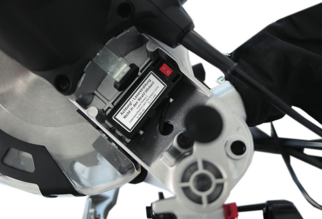
10 2 Maintenance and repair Pull out the mains plug for any adjustment or repair tasks. The generation of noise is influenced by various factors, including the characteristics of saw blades, condition of saw blade and electric tool. Use saw blades which were designed for reduced noise development, insofar as possible. Maintain the electric tool and tool attachments regularly and if necessary, initiate repairs in order to reduce noise. Report faults on the electric tool, protective devices or the tool attachment to the person responsible for safety as soon as they are discovered. 3 Safe work Only use saw blades for which the maximum permissible speed is not lower than the maximum spindle speed of table saws and which are suitable for the material to be cut. Make sure that the saw blade does not touch the rotary table in any position by pulling out the mains plug and rotating the saw blade by hand in the 45 and 90 position. If necessary, readjust the saw head. When transporting the electric tool, only use the transport devices. Never use the protective devices for handling or transport. Make sure that the lower part of the saw blade is covered during transport, e.g. by the protective device. Be sure to only use spacers and spindle rings specified by the manufacturer as suitable for the intended purpose. The floor around the machine must be level, clean and free of loose particles, such as chips and cutting residues. Do not remove any cutting residues or other parts of workpieces from the cutting zone while the machine is running with unprotected saw blade and the saw unit is not at rest. Make sure that the machine is always secured on a workbench or a table if at all possible. Support long workpieces (e.g. with a roller table) to prevent them sagging at the end of a cut. Warning! This electric tool generates an electromagnetic field during operation. This field can impair active or passive medical implants under certain conditions. In order to prevent the risk of serious or deadly injuries, we recommend that persons with medical implants consult with their physician and the manufacturer of the medical implant prior to operating the electric tool. SAFETY INSTRUCTIONS FOR THE HANDLING OF SAW BLADES 1 Only use insertion tools if you have mastered their use. 2 Observe the maximum speed. The maximum speed specified on the insertion tool may not be exceeded. If specified, observe the speed range. 3 Observe the motor / saw blade direction of rotation. 4 Do not use any insertion tools with cracks. Sort out cracked insertion tools. Repairs are not permitted. 5 Clean grease, oil and water off of the clamping surfaces. 6 Do not use any loose reducing rings or bushes for the reducing of holes on saw blades. 7 Make sure that fixed reducer rings for securing the insertion tool have the same diameter and have at least 1/3 of the cutting diameter. 8 Make sure that fixed reducer rings are parallel to each other. 9 Handle insertion tool with caution. They are ideally stored in the originally package or special containers. Wear protective gloves in order to improve grip and to further reduce the risk of injury. 10 Prior to the use of insertion tools, make sure that all protective devices are properly fastened. 11 Prior to use, make sure that the insertion tool meets the technical requirements of this electric tool and is properly fastened. 12 Only use the supplied saw blade for cutting wood, never for the processing of metals. 13 Warning! Never use the saw to cut other than the determined materials. 14 Only use the saw if the protective devices are functional, in good condition and in the intended position. 15 Ensure that the workpiece is always clamped at the saw table. 16 Before each sawing operation, make sure that the machine is secure. Attention: Laser radiation Do not stare into the beam Class 2 laser Protect yourself and you environment from accidents using suitable precautionary measures! Do not look directly into the laser beam with unprotected eyes. Never look into the path of the beam. Never point the laser beam towards reflecting surfaces and persons or animals. Even a laser beam with a low output can cause damage to the eyes. Caution - methods other than those specified here can result in dangerous radiation exposure. Never open the laser module. Unexpected exposure to the beam can occur. If the mitre saw is not used for an extended period of time, the batteries should be removed. The laser may not be replaced with a different type of laser. Repairs of the laser may only be carried out by the laser manufacturer or an authorised representative. Safety instructions for handling batteries 1 Always make sure that the batteries are inserted with the correct polarity (+ and ), as indicated on the battery. 2 Do not short-circuit batteries. 3 Do not charge non-rechargeable batteries. 4 Do not overcharge batteries! GB/IE/NI 5
11 5 Do not mix old and new batteries or batteries of different types or manufacturers! Replace an entire set of batteries at the same time. 6 Immediately remove used batteries from the device and dispose of them properly! Do not dispose batteries with household waste. Defective or used batteries must be recycled according to Directive 2006/66 / EC. Give back batteries and / or the device has been offered to the collective facilities. About disposal facilities you can inform by your municipal or city government. 7 Do not allow batteries to heat up! 8 Do not weld or solder directly on batteries! 9 Do not dismantle batteries! 10 Do not allow batteries to deform! 11 Do not throw batteries into fire! 12 Keep batteries out of the reach of children. 13 Do not allow children to replace batteries without supervision! 14 Do not keep batteries near fire, ovens or other sources of heat. Do not use batteries in direct sunlight or store them in vehicles in hot weather. 15 Keep unused batteries in the original packaging and keep them away from metal objects. Do not mix unpacked batteries or toss them together! This can lead to a short-circuit of the battery and thus damage, burns or even the risk of fire. 16 Remove batteries from the equipment when it will not be used for an extended period of time, unless it is for emergencies! 17 NEVER handle batteries that have leaked without appropriate protection. If the leaked fluid comes into contact with your skin, the skin in this area should be rinsed off under running water immediately. Always prevent the fluid from coming into contact with the eyes and mouth. In the event of contact, please seek immediate medical attention. 18 Clean the battery contacts and corresponding contacts in the device prior to inserting the batteries. Residual risks The machine has been built according to the state of the art and the recognised technical safety requirements. However, individual residual risks can arise during operation. Health hazard due to electrical power, with the use of improper electrical connection cables. Furthermore, despite all precautions having been met, some non-obvious residual risks may still remain. Residual risks can be minimised if the Important information, Additional safety instructions and the Proper use are observed along with the whole of the operating instructions. Do not load the machine unnecessarily: excessive pressure when sawing will quickly damage the saw blade, which results in reduced output of the machine in the processing and in cut precision. When cutting plastic material, please always use clamps: the parts which should be cut must always be fixed between the clamps. Avoid accidental starting of the machine: the operating button may not be pressed when inserting the plug in an outlet. Use the tool that is recommended in this manual. In doing so, your mitre saw provides optimal performance. Hands may never enter the processing zone when the machine is in operation. Release the handle button and switch off the machine prior to any operations. Assembly WARNING! For you own safety, only insert the mains plug in an outlet when all assembly steps have been completed and you have read and understood the safety and operating instructions. Lift the saw out of the packaging and place it on your work bench. (Positioning of the saw on the work bench - see the next page under POSITIONING / WORK STATION ) Installation of the dust bag (fig. 2) Squeeze together the metal ring on the chip bag (12) and attach it to the outlet opening in the motor area. Assembling the work piece clamping device (fig. 1.1) Loosen the locking screw (17) and attach the work piece clamping device (10) to the left or right of the fixed saw bench. Afterwards, retighten the locking screws (17). Assembling the work piece supports (fig ) Loosen the cross-head screw (14) and guide the work piece support through the specified hole on the side of the fixed saw bench. Make sure that the work piece support (15) is also guided through the two plates (19) on the underneath. Afterwards, retighten the cross-head screw (14). Repeat this process on the other side. Assembling the support stand (fig ) Loosen the cross-head screws (18) on the underneath of the saw and guide the support stand (16) through the specified holes on the back of the saw. Afterwards, retighten the cross-head screws (18). Commissioning Prior to commissioning, observe the safety instructions in the operating instructions. REMOVAL FROM THE PACKAGING Remove the machine from its package, which protects it during transport, without damaging the package in order to be able to use it later for transporting the mitre saw for long-term storage. MOVING Since the mitre saw is relatively small and light, its location can be easily changed, even by a single person. After locking the locking knob (26 - Fig. 4) in the bottom position, lift the mitre saw by the handle (34 - Fig. 4). 6 GB/IE/NI
12 TRANSPORT If the machine must be transported, carry it by the handle (34 - Fig. 4) and place it in the original packaging in which it was supplied. In the process, make sure that it is correctly positioned in the package (see arrows on the package). If possible, the load should be fixed with ropes or securing belts in order to prevent shifting during the transport or parts of the load from falling down. POSITIONING/WORK STATION Position the machine on a work bench or on a flat base so that the machine is supported as stably as possible. The equipment must be set up where it can stand secure, i.e. it should be bolted to a workbench, a universal base frame or similar. When working with the machine, ergonomic factors must be considered; the ideal height of the work table or the base is reached when the base surface or the upper work surface is 90 to 95 cm above the ground. The positioning of the machine must provide for at least 80 cm of clearance in all directions and in order to allow for cleaning and repair work as well as necessary adjustments in observance of safety conditions and with sufficient room to manoeuvre. CAUTION: Position the machine in a zone which is suitable in respect to the environmental conditions and lighting. Never forget that the general environmental conditions play an extremely important role in accident prevention. CONNECTION TO THE POWER SUPPLY Make sure that the socket is in a good condition. We would like to remind you that the power supply must be connected to a magnetic-thermal circuit breaker which protects all lines from short-circuits and overloading. Area of application Intended application possibilities The machine cuts: Wood and materials similar to wood Plastic Unintended application possibilities The machine is not suitable for: Ferritic materials, steel and cast iron, as well as other material types which are not listed, particularly food. Mitre saw without guard. Materials larger than the specified cutting data: 90 /90 / 120 x 60 mm 90 /45 80 x 60 mm 45 / x 35 mm 45 /45 80 x 35 mm Settings CROSS-CUTTING ATTENTION: Before carrying out the following adjustments, please check whether the motor of the machine is switched off. Pivoting the table plate (Fig. 2) The mitre saw can be pivoted left and right with the rotary table. Exact angle adjustment is possible on the basis of the scale. The angle can be precisely and quickly adjusted from 0 to 45 with locking positions at 15, 22.5 and 30. To pivot the rotary table, loosen the set screw (21) and rotate the unit using the handle (20) until the desired angle is reached. Then secure it with the set screw (21). Tilt of the saw unit (Fig. 3) The saw unit can be tilted at an angle of up to 45. Loosen the handle (23) on the rear side of the machine and tilt the unit to the desired angle position according to the scale. The angle can be set on the basis of the scale (24) using the pointer (25). Then the handle must be re-tightened. Working instructions After you have carried out all the tasks described above, you can begin working. ATTENTION: Always keep your hands away from the cutting zone and never attempt to reach in while cutting. FIXING A WORKPIECE Clamp the work piece on the work table with the workpiece clamp (10 - Fig 1) in order to fix it in place. Cross-cutting (Fig. 1, 1.3, 4) Attention! For 90 mitre cuts, the moveable stop rail (27a) must be fixed in the inner position. Open the set screw (27b) on the moveable stop rail (27a) with an Allen key and push the moveable stop rail (27a) inwards. The moveable stop rail (27a) must be locked in a position far enough from the inner position that the distance between the stop rail (27a) and the saw blade (5) is no more than 8 mm. Before making the cut, check that no collision could occur between the stop rail (27a) and the saw blade (5). Secure the locking lever (27b) again. Pressing the machine head lightly downwards and removing the locking bolt (26) from the motor bracket at the same time disengages the saw from the lowest position. Swing the machine head up until the release lever (3) latches into place. Lift the saw unit by the handle (2) until it locks in place in the top position. Lock the material with the clamping device (10) on the fixed saw table to prevent the material from moving during the cutting operation. Press the workpiece evenly on the stop strips (27); make sure that you hand remains outside the cutting area of the saw blade. With your right hand on the handle (2), press the locking lever (3) so that the unit can also be pivoted downward. The motor starts when the start button (1) is pressed. Slowly bring the saw blade down to the workpiece and cut through it with moderate pressure. When the cutting operation is completed, move the machine head back to its upper (home) position and release the ON/OFF button (1). GB/IE/NI 7
13 Attention! The machine executes an upward stroke automatically due to the return spring, i.e. do not release the handle (2) after completing the cut; instead allow the machine head to move upwards slowly whilst applying light counter pressure. Mitre cut 0-45 (Fig. 1, 1.3, 3) The crosscut saw can be used to make mitre cuts of 0-45 in relation to the work face. Important! To make miter cuts (inclined saw head), the adjustable stop rail (27a) must be fixed at the outer position. Open the set screw (27b) for the adjustable stop rail (27a) with an Allen key and push the adjustable stop rail outwards. The adjustable stop rail (27a) must be fixed far enough in front of the innermost position that the distance between the stop rail (27a) and the saw blade (5) amounts to a maximum of 8 mm. Before making a cut, check that the stop rail (27a) and the saw blade (5) cannot collide. Secure the locking lever (27b) again. Move the machine head to the top position. Fix the rotary table (9) in the 0 position. Loosen the set screw (23) and use the handle (2) to angle the machine head to the left, until the pointer (25) indicates the desired angle measurement on the scale (24). Re-tighten the fixing screw (23). Cut as described in section Cross-cutting. Mitre cut 0-45 and turntable 0-45 The crosscut saw can be used to make mitre cuts to the left of 0-45 in relation to the work face and, at the same time, 0-45 to the left or 0-45 to the right in relation to the stop rail (double mitre cut). Important! To make miter cuts (inclined saw head), the adjustable stop rail (27a) must be fixed at the outer position. Open the set screw (27b) for the adjustable stop rail (27a) with an Allen key and push the adjustable stop rail outwards. The adjustable stop rail (27a) must be fixed far enough in front of the innermost position that the distance between the stop rail (27a) and the saw blade (5) amounts to a maximum of 8 mm. Before making a cut, check that the stop rail (27a) and the saw blade (5) cannot collide. Secure the locking lever (27b) again. Move the machine head to its upper position. Release the rotary table (9) by loosening the set screw (23). Using the handle (2), set the rotary table (9) to the desired angle. Retighten the set screw (23) in order to secure the rotary table. Undo the locking screw (23) and use the handle (2) to tilt the machine head to the left until it coincides with the required angle value. Retighten the fixing screw (23). Cut as described in section Cross-cutting. Saw blade replacement (Fig. 5) Pull out the mains plug. Place the saw unit in cross-cutting position Unlock the moving saw blade guard (6) by pressing the locking lever (3 - Fig. 1); in the process, raise the saw blade guard so that the saw blade is free. Actuate the spindle lock (22 - Fig. 3). Loosen the saw blade fastening screw (28) - (Attention: left-handed thread). Remove the screw (28) and saw blade flange (29). Carefully remove the saw blade (risk of injury from the saw blade teeth). Place a new saw blade on the inner saw blade flange. In the process, observe the rotational direction of the saw blade. Fit the outer saw blade flange and firmly tighten the screw. Move the saw blade guard back to the correct position. Replacing laser batteries (Fig. 6) Remove the laser battery cover (30). Remove the 2 batteries. Replace both batteries with the same or an equivalent type. Make sure that they are inserted with the same polarity as the used batteries. Close the battery cover. Switch ON / switch OFF the laser (Fig. 6) To switch on: Move the ON/OFF (33) switch of the laser (34) to the 1 position. A laser line is projected onto the material you wish to process, providing an exact guide for the cut. To switch off: Move the ON/OFF switch of the laser to the 0 position. Adjusting the laser (Fig. 7) If the laser (31) ceases to indicate the correct cutting line, you can readjust the laser. To do so, open the screws (32) and set the laser by moving sideways to that the laser beam strikes the teeth of the saw blade (5). Electrical connection The electrical motor installed is connected and ready for operation. The connection complies with the applicable VDE and DIN provisions. The customer s mains connection as well as the extension cable used must also comply with these regulations. Important information In the event of an overloading the motor will switch itself off. After a cool-down period (time varies) the motor can be switched back on again. Damaged electrical connection cable The insulation on electrical connection cables is often damaged. This may have the following causes: Passage points, where connection cables are passed through windows or doors. Kinks where the connection cable has been improperly fastened or routed. Places where the connection cables have been cut due to being driven over. Insulation damage due to being ripped out of the wall outlet. Cracks due to the insulation ageing. 8 GB/IE/NI
14 Such damaged electrical connection cables must not be used and are life-threatening due to the insulation damage. Check the electrical connection cables for damage regularly. Make sure that the connection cable does not hang on the power network during the inspection. Electrical connection cables must comply with the applicable VDE and DIN provisions. Only use connection cables with the marking H 07 RN. The printing of the type designation on the connection cable is mandatory. AC motor The mains voltage must be 230 V ~ Extension cables up to 25 m long must have a cross-section of 1.5 mm 2. Connections and repairs of electrical equipment may only be carried out by an electrician. Please provide the following information in the event of any enquiries: Type of current for the motor Machine data - type plate Machine data - type plate Accessories SAW DUST EXTRACTION The mitre saw is equipped with an extraction port to which an extraction system can be connected. Alternatively, a dust bag can also be attached. The hose of the extraction system is fastened on the extraction port with a clamp. We recommend emptying the bag or container from time to time and cleaning the filter. The air speed of the suction system must be at least 30 metres per second. In the event of service work, personal protective equipment must always be work (protective goggles and gloves). Remove saw dust and chips regularly by cleaning the cutting zone and support surfaces. We recommend using a suction tool or brush. ATTENTION: Do not use compressed air! Check the saw blade from time to time: If problems arise with the blade, it must be ground by a specialist or replaced, depending on the condition. DECOMMISSIONING OF THE MACHINE After the machine is decommissioned it can be disposed of with normal industrial waste. Disposal The packaging is wholly composed of environmentally-friendly materials that can be disposed of at a local recycling centre. Contact your local refuse disposal authority for more details of how to dispose of your worn out electrical devices. Maintenance If personnel qualified for unusual maintenance tasks or repairs must be obtained during of after the warranty period, please always contact a service point recommended by us or contact the manufacturer. Warning! Prior to any adjustment, maintenance or service work disconnect the mains power plug! Only perform repair, maintenance and cleaning work as well as the correction of malfunctions with the drive switched off as a basic rule. All protective and safety equipment must be reassembled immediately after repair, maintenance is completed. NORMAL SERVICE TASKS Normal service tasks can also be performed by untrained personnel and are all described in the preceding sections and in this chapter. The mitre saw must not be lubricated, because it always cuts dry surfaces; all moving machine parts are selflubricating. GB/IE/NI 9
15 Troubleshooting Fault Possible cause Remedy Motor does not work. Motor, cable or plug defective, fuses burnt. Arrange for inspection of the machine by a specialist. Never repair the motor yourself. Danger! Check fuses and replace as necessary. The motor starts up slowly and does not reach operating speed. Motor makes excessive noise. The motor does not reach its full power. Motor overheats easily. Reduced cutting power when sawing. Voltage too low, coils damaged, capacitor burnt. Coils damaged, motor defective. Circuits in the network are overloaded (lamps, other motors, etc.). Overloading of the motor, insufficient cooling of the motor. Saw blade too small (ground too much). Contact the utility provider to check the voltage. Arrange for inspection of the motor by a specialist. Arrange for replacement of the capacitor by a specialist. Arrange for inspection of the motor by a specialist. Do not use any other equipment or motors on the same circuit. Avoid overloading the motor while cutting, remove dust from the motor in order to ensure optimal cooling of the motor. Readjust end stop of the saw unit. Saw cut is rough or wavy. Workpiece pulls away and/or splinters. Saw blade dull, tooth shape not appropriate for the material thickness. Excessive cutting pressure and/or saw blade not suitable for use. Resharpen saw blade and/or use suitable saw blade. Insert suitable saw blade. 10 GB/IE/NI
16 GUARANTEE CERTIFICATE Dear Customer, All of our products undergo strict quality checks to ensure that they reach you in perfect condition. In the unlikely event that your device develops a fault, please contact our service department at the address shown on this guarantee card. Of course, if you would prefer to call us then we are also happy to offer our assistance under the service number printed below. Please note the following terms under which guarantee claims can be made: These guarantee terms cover additional guarantee rights and do not affect your statutory warranty rights. We do not charge you for this guarantee. Our guarantee only covers problems caused by material or manufacturing defects, and it is restricted to the rectification of these defects or replacement of the device. Please note that our devices have not been designed for use in commercial, trade or industrial applications. Consequently, the guarantee is invalidated if the equipment is used in commercial, trade or industrial applications or for other equivalent activities. The following are also excluded from our guarantee: compensation for transport damage, damage caused by failure to comply with the installation/assembly instructions or damage caused by unprofessional installation, failure to comply with the operating instructions (e.g. connection to the wrong mains voltage or current type), misuse or inappropriate use (such as overloading of the device or use of non-approved tools or accessories), failure to comply with the maintenance and safety regulations, ingress of foreign bodies into the device (e.g. sand, stones or dust), effects of force or external influences (e.g. damage caused by the device being dropped) and normal wear resulting from proper operation of the device. The guarantee is rendered null and void if any attempt is made to tamper with the device. The guarantee is valid for a period of 3 years starting from the purchase date of the device. Guarantee claims should be submitted before the end of the guarantee period within two weeks of the defect being noticed. No guarantee claims will be accepted after the end of the guarantee period. The original guarantee period remains applicable to the device even if repairs are carried out or parts are replaced. In such cases, the work performed or parts fitted will not result in an extension of the guarantee period, and no new guarantee will become active for the work performed or parts fitted. This also applies when an on-site service is used. In order to assert your guarantee claim, please send your defective device postage-free to the address shown below. Please enclose either the original or a copy of your sales receipt or another dated proof of purchase. Please keep your sales receipt in a safe place, as it is your proof of purchase. It would help us if you could describe the nature of the problem in as much detail as possible. If the defect is covered by our guarantee then your device will either be repaired immediately and returned to you, or we will send you a new device. Of course, we are also happy offer a chargeable repair service for any defects which are not covered by the scope of this guarantee or for units which are no longer covered. To take advantage of this service, please send the device to our service address. Service-Hotline: (0,00 /Min.) Service- (GB/IE/NI): lidl.service.gb@scheppach.com lidl.service.ie@scheppach.com lidl.service.ni@scheppach.com Service address (GB/IE/NI): GreatStar Europe Unit 55 Romsey Industrial Estate, Romsey Hampshire SO51 0HR GB/IE/NI 11
17 Περιεχόμενα: Σελίδα: εισαγωγή 13 Ενδεδειγμένη χρήση 14 Σημαντικές υποδείξεις 14 Πρόσθετες υποδείξεις ασφαλείας 16 Υπολειπόμενοι κίνδυνοι 18 Θέση σε λειτουργία 19 Συναρμολόγηση 19 Πεδίο χρήσης 20 Ρυθμίσεις 20 Υποδείξεις εργασίας 20 Σύνδεση στο ηλεκτρικό ρεύμα 21 Αξεσουάρ 21 Συντήρηση 21 Απόσυρση 22 Αντιμετώπιση προβλημάτων 22 Εγγύηση 24 Δήλωση συμμόρφωσης GR/CY
18 εισαγωγή ΚΑΤΑΣΚΕΥΑΣΤΉΣ: scheppach Fabrikation von Holzbearbeitungsmaschine GmbH Günzburger Straße 69 D Ichenhausen ΣΥΜΒΟΥΛΉ, Σύμφωνα με την υφιστάμενη νομοθεσία περί ευθύνης προϊόντος, ο κατασκευαστής αυτής της συσκευής δεν ευθύνεται για ζημιές που προκύπτουν από ή σε σχέση με αυτή τη συσκευή σε περίπτωση: ανάρμοστου χειρισμού, μη συμμόρφωσης με τις οδηγίες χρήσης, επισκευών από τρίτους, μη εξουσιοδοτημένων εξειδικευμένων εργατών, εγκατάστασης και αντικατάστασης μη-αυθεντικών ανταλλακτικών, ανάρμοστης χρήσης, βλαβών του ηλεκτρικού συστήματος λόγω της μη συμμόρφωσης με τις ηλεκτρικές προδιαγραφές και τους κανονισμούς VDE0100, DIN / VDE ΣΥΣΤΆΣΕΙΣ: Διαβάστε ολόκληρο το κείμενο των οδηγιών λειτουργίας πριν από τη συναρμολόγηση και τη λειτουργία της συσκευής. Αυτές οι οδηγίες λειτουργίας προορίζονται να σας διευκολύνουν να εξοικειωθείτε με τη συσκευή σας και να χρησιμοποιήσετε όλες τις δυνατότητες για τις οποίες προορίζεται. Οι οδηγίες λειτουργίας περιέχουν σημαντικές σημειώσεις για το πώς να εργαστείτε με ασφάλεια, κατάλληλα και οικονομικά με τη μηχανή σας και πώς να αποφύγετε κινδύνους, να εξοικονομήσετε δαπάνες επισκευής, να μειώσετε το χρόνο διακοπής και να αυξήσετε την αξιοπιστία και τη διάρκεια ζωής της μηχανής. Εκτός από τους κανονισμούς ασφάλειας που περιλαμβάνονται στο παρόν, πρέπει εν πάση περιπτώσει να συμμορφωθείτε με τους εφαρμοστέους κανονισμούς της χώρας σας όσον αφορά στη λειτουργία της μηχανής. Τοποθετήστε τις οδηγίες λειτουργίας σε ένα διαφανή πλαστικό φάκελο ώστε να τις προστατεύσετε από ρύπους και υγρασία και αποθηκεύστε τις κοντά στη μηχανή. Οι οδηγίες πρέπει να διαβαστούν και να τηρούνται προσεκτικά από κάθε χειριστή πριν από την εκκίνηση της εργασίας. Μόνο τα πρόσωπα που έχουν εκπαιδευθεί ως προς τη χρήση της μηχανής και έχουν ενημερωθεί για τους σχετικούς κινδύνους και απειλές έχουν την άδεια να χρησιμοποιήσουν τη μηχανή. Η απαραίτητη ελάχιστη ηλικία πρέπει να πληρείται. Εκτός από τις σημειώσεις ασφάλειας που περιλαμβάνονται στις παρούσες οδηγίες λειτουργίας και τους ιδιαίτερους κανονισμούς της χώρας σας, πρέπει να τηρούνται οι γενικά αναγνωρισμένοι τεχνικοί κανόνες για τη λειτουργία ξυλουργικών μηχανών. Δεν αναλαμβάνουμε καμία ευθύνη για ατυχήματα ή ζημιές που θα προκύψουν από μη τήρηση αυτών των οδηγιών και των υποδείξεων ασφαλείας. Λεζάντα της εικ Κουμπί εκκίνησης 2. Χειρολαβή 3. Μοχλός ασφάλισης 4. Μοτέρ 5. Λάμα πριονιού 6. Προστατευτικό λάμας πριονιού, κινητό 7. Βάση 8. Ένθετο τραπεζιού 9. Στρεφόμενο τραπέζι 10. Σφιγκτήρας τεμαχίων εργασίας 11. Άρθρωση, περίβλημα / βάση 12. Σακούλα συλλογής πριονιδιών 13. Προστατευτικό λάμας πριονιού, σταθερό PKS 1500 A2 Αντικείμενο παράδοσης Φαλτσοπρίονο Σακούλα συλλογής πριονιδιών Σφιγκτήρας τεμαχίων εργασίας Εργαλείο για αντικατάσταση λάμας πριονιού - κλειδί άλεν 6 mm Εργαλείο για ρυθμιζόμενου οδηγού - κλειδί άλεν 3 mm 2 υποστηρίγματα τεμαχίου εργασίας Βάση στήριξης 2 ψήκτρες άνθρακα 2 μπαταρίες (AAA) Οδηγίες χειρισμού Τεχνικά δεδομένα Διαστάσεις κατασκευής Μ 690 x 550 x 440 x Π x Υ mm ø Στρεφόμενο τραπέζι mm 385 x 150 Ύψος τραπεζιού mm /30/2,6/1,6 WZ Λάμα πριονιού ø mm 48 Αριθμός στροφών 1/min 5000 Ταχύτητα κοπής m/s 55 Εύρος στροφής 2 x 45 Γωνία κλίσης 45 Διπλή λοξή κοπή 45 x 45 links 45, 30, 22,5, 15, Θέσεις συγκράτησης 0, 15, 22,5, 30, 45 Βάρος kg 7,7 Δεδομένα λειτουργίας κοπής μέγ. βάθος κοπής 60 / 35 mm 90 /45 90 / x 60 mm 90 /45 80 x 60 mm 45 / x 35 mm 45 /45 80 x 35 mm Μονάδα κίνησης V~/Hz του μοτέρ / 50 S1 1200W Κατανάλωση ισχύος W S6 25%* 1500W GR/CY 13
19 Με την επιφύλαξη τεχνικών τροποποιήσεων! * Τρόπος λειτουργίας S6, αδιάλειπτη περιοδική λειτουργία. Η λειτουργία αποτελείται από ένα χρονικό διάστημα εκκίνησης, ένα χρονικό διάστημα με σταθερό φορτίο και ένα χρονικό διάστημα λειτουργίας χωρίς φορτίο. Ο κύκλος δραστηριότητας είναι 10 λεπτά, η σχετική διάρκεια ενεργοποιημένης κατάστασης είναι 25% του κύκλου δραστηριότητας. Το τεμάχιο εργασίας πρέπει να έχει τουλάχιστον ύψος 3 mm και πλάτος 10 mm. Προσέχετε το τεμάχιο εργασίας να στερεώνεται πάντα με τη διάταξη σύσφιξης. Πληροφορίες σχετικά με την εκπομπή θορύβου Οι τιμές στάθμης θορύβου αυτού του μηχανήματος κατά τη διάρκεια λειτουργίας του είναι οι εξής: L pa : 99.6dB(A) K=3dB(A) L wa : 112.6dB(A) K=3dB(A) Προειδοποίηση: Ο θόρυβος μπορεί να έχει σοβαρές επιπτώσεις στην υγεία σας. Αν ο θόρυβος του μηχανήματος υπερβαίνει τα 85 db (A), να φοράτε κατάλληλη προστασία ακοής. Σε περίπτωση προβλήματος στην ηλεκτρική σύνδεση, μπορεί να υπάρξει πτώση της τάσης κατά την εκκίνηση του μηχανήματος. Αυτό μπορεί να επηρεάσει άλλα μηχανήματα (π.χ. αναβοσβήσιμο φώτων). Αν η ηλεκτρική ισχύς αντιστοιχεί σε Zmax < 0,27, δεν θα πρέπει να προκύψουν τέτοια προβλήματα. (Αν ναι, απευθυνθείτε στο συνεργαζόμενο εξειδικευμένο κατάστημα). Η αναφερόμενη τιμή εκπομπών κραδασμών έχει μετρηθεί σύμφωνα με πρότυπη διαδικασία ελέγχου και μπορεί να χρησιμοποιηθεί για τη σύγκριση ενός ηλεκτρικού εργαλείου με ένα άλλο. Η αναφερόμενη τιμή εκπομπών κραδασμών μπορεί να χρησιμοποιηθεί και για μια πρώτη αξιολόγηση της καταπόνησης. Ενδεδειγμένη χρήση Το φαλτσοπρίονο εξυπηρετεί στο κόψιμο ξύλων και πλαστικού, ανάλογα με το μέγεθος της μηχανής. Προειδοποίηση! Η λάμα πριονιού που συμπεριλαμβάνεται προορίζεται αποκλειστικά για την κοπή ξύλου! Μην τον χρησιμοποιείτε για την κοπή πλαστικού! Η μηχανή να χρησιμοποιείται μόνο για το σκοπό για τον οποίο προορίζεται. Κάθε πέραν τούτου χρήση δεν είναι ενδεδειγμένη. Για ζημιές ή τραυματισμούς παντός είδους που οφείλονται σε μη ενδεδειγμένη χρήση ευθύνεται ο χρήστης / χειριστής και όχι ο κατασκευαστής. Επιτρέπεται μόνο η χρήση πριονοδίσκων κατάλληλων για τη μηχανή. Απαγορεύεται η χρήση διαχωριστικών δίσκων παντός είδους. Αναπόσπαστο μέρος της ενδεδειγμένης χρήσης είναι και η τήρηση των υποδείξεων ασφαλείας, καθώς και η οδηγία συναρμολόγησης και οι υποδείξεις χειρισμού στην οδηγία χρήσης. Τα άτομα που χειρίζονται τη μηχανή, πρέπει να είναι εξοικειωμένα με το χειρισμό της και να ενημερωθούν για ενδεχόμενους κινδύνους. Πέραν τούτου να τηρούνται αυστηρά οι διατάξεις πρόληψης ατυχημάτων. Να ακολουθούνται επίσης και οι άλλοι γενικοί κανόνες ιατρικής εργασίας και τεχνικής ασφάλειας. Τροποποιήσεις στη μηχανή αποκλείουν την ευθύνη του κατασκευαστή από τις ζημιές που προκύπτουν από τη χρήση αυτή. Παρ όλη την ενδεδειγμένη χρήση δεν μπορούν να αποκλειστούν τελείως ορισμένοι κίνδυνοι. Εξαιτίας της κατασκευής και της δομής της μηχανής δεν αποκλείονται τα εξής: Επαφή με τον πριονοδίσκο στο ακάλυπτο τμήμα της. Επέμβαση στον κινούμενο πριονοδίσκο (τραυματισμός από αιχμηρό αντικείμενο) Εκσφενδονισμός κατεργαζόμενων αντικειμένων ή τμημάτων τους. Θραύση πριονόδισκου. Εκσφενδονισμός ελαττωματικών τμημάτων σκληρού μετάλλου του πριονοδίσκου. Βλάβη της ακοής όταν δεν χρησιμοποιούνται οι απαιτούμενες ωτοασπίδες. Επιβλαβείς για την υγεία εκπομπές σκόνης ξύλου κατά τη χρήση σε κλειστούς χώρους. Παρακαλούμε να προσέξετε, πως οι συσκευές μας δεν έχουν κατασκευαστεί για επαγγελματική, βιοτεχνική και βιομηχανική χρήση. Δεν αναλαμβάνουμε καμμία εγγύηση, εάν η συσκευή χρησιμοποιηθεί σε βιοτεχνίες ή βιομηχανίες ή σε παρόμοιες εργασίες. Σημαντικές υποδείξεις Προσοχή! Κατά τη χρήση ηλεκτρικών εργαλείων πρέπει να τηρείτε τα εξής βασικά μέτρα ασφαλείας, για προστασία από ηλεκτροπληξία και από κίνδυνο τραυματισμού και φωτιάς. Διαβάστε όλες αυτές τις υποδείξεις πριν χρησιμοποιήσετε αυτό το ηλεκτρικό εργαλείο και φυλάξτε καλά τις υποδείξεις ασφαλείας. Ασφάλεια κατά την εργασία 1 Να κρατάτε τη θέση εργασίας πάντα τακτική. Μία όχι τακτική θέση εργασία προακελί κινδύνους ατυχημάτων. 2 Να λάβετε υπόψη τις επιδράσεις του περιβάλλοντος Μην εκθέτετε ηλεκτρικές συσκευές σε βροχή. Ποτέ μη χρησιμοποιείτε τα ηλεκτρικά εργαλεία σε υγρό περιβάλλον. Φροντίστε για καλό φωτισμό. Μη χρησιμοποιείτε ηλεκτρικά εργαλεία σε περιβάλλον όπου υπάρχει κίνδυνος φωτιάς και έκρηξης. 14 GR/CY
Περιεχόμενα / Contents
 Aερόθερμo / Fan Heater PTC-906 Περιεχόμενα / Contents GR... Σελίδες 3-8 EN... Pages 9-11 2 GR Ευχαριστούμε που επιλέξατε μια συσκευή της γκάμας θερμαντικών IZZY. Σημαντικές Οδηγίες Ασφαλείας Τα Μέρη της
[1] P Q. Fig. 3.1
![[1] P Q. Fig. 3.1](/thumbs/79/80362156.jpg "[1] P Q. Fig. 3.1") 1 (a) Define resistance....... [1] (b) The smallest conductor within a computer processing chip can be represented as a rectangular block that is one atom high, four atoms wide and twenty atoms long. One
1 (a) Define resistance....... [1] (b) The smallest conductor within a computer processing chip can be represented as a rectangular block that is one atom high, four atoms wide and twenty atoms long. One
IAN 102787 MITRE SAW PKS 1500 A1 ΦΑΛΤΣΟΠΡΙΟΝΟ PKS 1500 A1
 MITRE SAW PKS 1500 A1 ΦΑΛΤΣΟΠΡΙΟΝΟ PKS 1500 A1 GB IE CY MITRE SAW PKS 1500 A1 Operating and Safety Instructions Translation of Original Operating Manual GR CY ΦΑΛΤΣΟΠΡΙΟΝΟ PKS 1500 A1 Οδηγίες χειρισμού
the total number of electrons passing through the lamp.
 1. A 12 V 36 W lamp is lit to normal brightness using a 12 V car battery of negligible internal resistance. The lamp is switched on for one hour (3600 s). For the time of 1 hour, calculate (i) the energy
IAN 93463 ΦΑΛΤΣΟΠΡΙΟΝΟ PKS 1500 A1. ΦΑΛΤΣΟΠΡΙΟΝΟ PKS 1500 A1 Οδηγίες χειρισμού και ασφαλείας Μετάφραση του πρωτοτύπου των οδηγιών χρήσης
 ΦΑΛΤΣΟΠΡΙΟΝΟ PKS 1500 A1 GB CY MITRE SAW PKS 1500 A1 Operating and Safety Instructions Translation of Original Operating Manual GR CY ΦΑΛΤΣΟΠΡΙΟΝΟ PKS 1500 A1 Οδηγίες χειρισμού και ασφαλείας Μετάφραση
Capacitors - Capacitance, Charge and Potential Difference
 Capacitors - Capacitance, Charge and Potential Difference Capacitors store electric charge. This ability to store electric charge is known as capacitance. A simple capacitor consists of 2 parallel metal
Instruction Execution Times
 1 C Execution Times InThisAppendix... Introduction DL330 Execution Times DL330P Execution Times DL340 Execution Times C-2 Execution Times Introduction Data Registers This appendix contains several tables
UDZ Swirl diffuser. Product facts. Quick-selection. Swirl diffuser UDZ. Product code example:
 UDZ Swirl diffuser Swirl diffuser UDZ, which is intended for installation in a ventilation duct, can be used in premises with a large volume, for example factory premises, storage areas, superstores, halls,
Οδηγίες Λειτουργίας. Assembly Operating instructions. Montageanleitung. Απογυμνωτές PV-AZM...3. Stripping pliers PV-AZM...3.
 MA000 MA267 (de_en) (gr_en) Montageanleitung Οδηγίες Λειτουργίας Απογυμνωτής PV-AZM... για MC3, MC4 MA000 MA267 (de_en) (gr_en) Assembly Operating instructions Stripping pliers PV-AZM... for MC3 and MC4
Door Hinge replacement (Rear Left Door)
") Door Hinge replacement (Rear Left Door) We will continue the previous article by replacing the hinges of the rear left hand side door. I will use again the same procedure and means I employed during the
Door Hinge replacement (Rear Left Door) We will continue the previous article by replacing the hinges of the rear left hand side door. I will use again the same procedure and means I employed during the
IAN 46876 SLIDING CROSS CUT MITRE SAW PZKS 1500 A1
 SLIDING CROSS CUT MITRE SAW PZKS 1500 A1 GB CY GR CY SLIDING CROSS CUT MITRE SAW PZKS 1500 A1 Operating and Safety Instructions Translation of Original Operating Manual ΦΑΛΤΣΟΠΡΙΟΝΟ ΚΑΙ ΠΡΙΟΝΙ ΚΑΘΕΤΗΣ
ΟΔΗΓΙΕΣ ΕΓΚΑΤΑΣTΑΣΗΣ ΓΙΑ ΠΑΤΩΜΑ WPC INSTALLATION GUIDE FOR WPC DECKING
 1/12 ΟΔΗΓΙΕΣ ΕΓΚΑΤΑΣTΑΣΗΣ ΓΙΑ ΠΑΤΩΜΑ WPC INSTALLATION GUIDE FOR WPC DECKING Ανοίγουμε τρύπες Ø8 x 80mm στο σημείο κατασκευής, με τρυπάνι. To προτεινόμενο πλάτος και μήκος μεταξύ των 2 οπών να είναι 30-35εκ.,
Εγκατάσταση λογισμικού και αναβάθμιση συσκευής Device software installation and software upgrade
 Για να ελέγξετε το λογισμικό που έχει τώρα η συσκευή κάντε κλικ Menu > Options > Device > About Device Versions. Στο πιο κάτω παράδειγμα η συσκευή έχει έκδοση λογισμικού 6.0.0.546 με πλατφόρμα 6.6.0.207.
ΟΔΗΓΙΕΣ ΣΥΝΑΡΜΟΛΟΓΗΣΗΣ/ ASSEMBLY INSTRUCTION ΤΟΜΜΥ ΚΡΕΒΑΤΙ/BED
 ΟΔΗΓΙΕΣ ΣΥΝΑΡΜΟΛΟΓΗΣΗΣ/ ASSEMBLY INSTRUCTION ΤΟΜΜΥ ΚΡΕΒΑΤΙ/BED 1. Παρακαλώ πολύ διαβάστε προσεκτικά τις οδηγίες πριν την συναρμολόγηση/ Please read the instructions carefully. 2. Παρακαλώ πολύ όπως ελέγξτε
Surface Mount Multilayer Chip Capacitors for Commodity Solutions
 Surface Mount Multilayer Chip Capacitors for Commodity Solutions Below tables are test procedures and requirements unless specified in detail datasheet. 1) Visual and mechanical 2) Capacitance 3) Q/DF
ZLW Series. Single-stage Monoblock Centrifugal Pump ZL PUMP GROUP.,LTD
 ZLW Series Single-stage Monoblock Centrifugal Pump ZL PUMP GROUP.,LTD 1 Application Apply as the transportation of liquids in the fields of air condition, heating, sanitary water, water treatment cooling,
Potential Dividers. 46 minutes. 46 marks. Page 1 of 11
 Potential Dividers 46 minutes 46 marks Page 1 of 11 Q1. In the circuit shown in the figure below, the battery, of negligible internal resistance, has an emf of 30 V. The pd across the lamp is 6.0 V and
ΟΔΗΓΙΕΣ ΧΡΗΣΗΣ USE INSTRUCTIONS
 ΟΔΗΓΙΕΣ ΧΡΗΣΗΣ USE INSTRUCTIONS ΤΗΛΕΦΩΝΟ ΜΕ ΑΝΑΓΝΩΡΙΣΗ ΚΛΗΣΗΣ /CORDED PHONE WITH CALLER ID ΜΟΝΤΕΛΟ/MODEL: TM09-448 DC48V Παρακαλούμε διαβάστε προσεκτικά όλες τις οδηγίες χρήσης πριν την χρήση της συσκευής
MS SERIES MS DESK TOP ENCLOSURE APPLICATION EXAMPLE FEATURE. Measuring instruments. Power supply equipments
 MS SERIES MS DESK TOP ENCLOSURE FEATURE Available in 176 sizes. Screws are not appeared on the surface. Usable as rack mount case with optinal mounting bracket. There are no ventilation hole for cover
Right Rear Door. Let's now finish the door hinge saga with the right rear door
 Right Rear Door Let's now finish the door hinge saga with the right rear door You may have been already guessed my steps, so there is not much to describe in detail. Old upper one file:///c /Documents
 60 61 62 63 64 65 Ο Δ Η Γ Ι Ε Σ Σ Υ Ν Τ Η Ρ Η Σ Η Σ Τ Ω Ν Κ Ο Υ Φ Ω Μ Α Τ Ω Ν Ι Ν S T R U C T I N O N S C O N C E R N I N G Τ Η Ε C A S E M E N T S M A I N T E N A N C E Ο τακτικός καθαρισμός των βαμμένων
Presenter SNP6000. Register your product and get support at Εγχειρίδιο χρήσης
 Register your product and get support at www.philips.com/welcome Presenter SNP6000 EL Εγχειρίδιο χρήσης 1 a b c d e 2 3 4 Federal Communication Commission Interference Statement This equipment has been
Bbc7000 ΦΟΡΤΙΣΤΗΣ - ΕΚΚΙΝΗΤΗΣ ΜΠΑΤΑΡΙΑΣ. Art Nr: Owner s manual. Μετάφραση του πρωτοτύπου των οδηγιών χρήσης
 Bbc7000 ΦΟΡΤΙΣΤΗΣ - ΕΚΚΙΝΗΤΗΣ ΜΠΑΤΑΡΙΑΣ Μετάφραση του πρωτοτύπου των οδηγιών χρήσης Art Nr: 022213 Owner s manual Διαβάστε προσεχτικά όλες τις οδηγίες χρήσης και ασφάλειας πριν την λειτουργία του μηχανήματος.
ΚΥΠΡΙΑΚΗ ΕΤΑΙΡΕΙΑ ΠΛΗΡΟΦΟΡΙΚΗΣ CYPRUS COMPUTER SOCIETY ΠΑΓΚΥΠΡΙΟΣ ΜΑΘΗΤΙΚΟΣ ΔΙΑΓΩΝΙΣΜΟΣ ΠΛΗΡΟΦΟΡΙΚΗΣ 19/5/2007
 Οδηγίες: Να απαντηθούν όλες οι ερωτήσεις. Αν κάπου κάνετε κάποιες υποθέσεις να αναφερθούν στη σχετική ερώτηση. Όλα τα αρχεία που αναφέρονται στα προβλήματα βρίσκονται στον ίδιο φάκελο με το εκτελέσιμο
User s Manual / Οδηγίες Χρήσης
 User s Manual / Οδηγίες Χρήσης EUROPEAN STANDARDS Your child s safety depends on you. Proper bed rail usage cannot be assured unless you follow these instructions. DO NOT USE YOUR BED RAIL UNTILL YOU READ
Strain gauge and rosettes
 Strain gauge and rosettes Introduction A strain gauge is a device which is used to measure strain (deformation) on an object subjected to forces. Strain can be measured using various types of devices classified
Code Breaker. TEACHER s NOTES
 TEACHER s NOTES Time: 50 minutes Learning Outcomes: To relate the genetic code to the assembly of proteins To summarize factors that lead to different types of mutations To distinguish among positive,
VENERE. GR. Οδηγός Χρήσης EN. User Guide
 GR. Οδηγός Χρήσης EN. User Guide ΣΗΜΑΝΤΙΚΟ! ΚΡΑΤΗΣΤΕ ΓΙΑ ΜΕΛΛΟΝΤΙΚΗ ΑΝΑΦΟΡΑ: ΔΙΑΒΑΣΤΕ ΠΡΟΣΕΚΤΙΚΑ Κίνδυνος από φωτιά και άλλες πηγές έντονης θερμότητας, όπως ηλεκτρικές αντιστάσεις, υγραέριο, φωτιά κλπ,
Modbus basic setup notes for IO-Link AL1xxx Master Block
 n Modbus has four tables/registers where data is stored along with their associated addresses. We will be using the holding registers from address 40001 to 49999 that are R/W 16 bit/word. Two tables that
Precision Metal Film Fixed Resistor Axial Leaded
 Features EIA standard colour-coding Non-Flame type available Low noise and voltage coefficient Low temperature coefficient range Wide precision range in small package Too low or too high ohmic value can
NMBTC.COM /
 Common Common Vibration Test:... Conforms to JIS C 60068-2-6, Amplitude: 1.5mm, Frequency 10 to 55 Hz, 1 hour in each of the X, Y and Z directions. Shock Test:...Conforms to JIS C 60068-2-27, Acceleration
MSN DESK TOP ENCLOSURE WITH STAND / CARRYING HANDLE
 MSN SERIES MSN DESK TOP ENCLOSURE WITH STAND / CARRYING HANDLE W H FEATURE Available in 176 sizes. Stand / carrying handle can be adjusted in 30 degree. Maximum load is kg. There are no ventilation hole
Quick Installation Guide
 A Installation 1 F H B E C D G 2 www.trust.com/17528/faq Quick Installation Guide C C D Freewave Wireless Audio Set 17528/ 17529 D Installation Configuration Windows XP 4 5 8 Windows 7/ Vista 6 7 9 10
Operating Instructions and Parts Manual 14-inch Woodworking Band Saw Models JWBS-14SF and JWBS-14SF-3
 Operating Instructions and Parts Manual 14-inch Woodworking Band Saw Models JWBS-14SF and JWBS-14SF-3 Model #714500 shown JET 427 New Sanford Road LaVergne, Tennessee 37086 Part No. M-714500 Ph.: 800-274-6848
RSDW08 & RDDW08 series
 /,, MODEL SELECTION TABLE INPUT ORDER NO. INPUT VOLTAGE (RANGE) NO LOAD INPUT CURRENT FULL LOAD VOLTAGE CURRENT EFFICIENCY (Typ.) CAPACITOR LOAD (MAX.) RSDW08F-03 344mA 3.3V 2000mA 80% 2000μF RSDW08F-05
TIME SWITCHES AND TWILIGHT SWITCHES
 W ANALOG DIN-RAIL TIME SWITCH QUARTZ, SERIES TEMPUS ANALOG 244 W SCHRACK-INFO Analogue time switch 1 channel Daily program With power reserve (NiMH rechargeable battery) Synchronised with mains Shortest
Thin Film Chip Resistors
 FEATURES PRECISE TOLERANCE AND TEMPERATURE COEFFICIENT EIA STANDARD CASE SIZES (0201 ~ 2512) LOW NOISE, THIN FILM (NiCr) CONSTRUCTION REFLOW SOLDERABLE (Pb FREE TERMINATION FINISH) Type Size EIA PowerRating
derivation of the Laplacian from rectangular to spherical coordinates
 derivation of the Laplacian from rectangular to spherical coordinates swapnizzle 03-03- :5:43 We begin by recognizing the familiar conversion from rectangular to spherical coordinates (note that φ is used
Εγγύηση καλής λειτουργίας
 Εγγύηση καλής λειτουργίας Τα Smartphone Bitmore συνοδεύονται από Εγγύηση Καλής Λειτουργίας Δύο (2) Ετών. Please read carefully the Παρακαλούμε διαβάστε προσεκτικά τους όρους εγγύησης που συνοδεύουν το
1 Alumina Substrate 4 Edge Electrode (NiCr) 7 Resistor Layer (NiCr) 2 Bottom Electrode (Ag) 5 Barrier Layer (Ni) 8 Overcoat (Epoxy)
 7 Resistor Layer (NiCr) 2 Bottom Electrode (Ag) 5 Barrier Layer (Ni) 8 Overcoat (Epoxy)") ARN series Thin Film High Precision Chip Resistor Features» Advanced thin film technology» Very tight tolerance down to ±0.01%» Extremely low TCR down to ±5ppm/» Wide resistance range 1ohm-3Mega ohm» Miniature
ARN series Thin Film High Precision Chip Resistor Features» Advanced thin film technology» Very tight tolerance down to ±0.01%» Extremely low TCR down to ±5ppm/» Wide resistance range 1ohm-3Mega ohm» Miniature
2 Composition. Invertible Mappings
 Arkansas Tech University MATH 4033: Elementary Modern Algebra Dr. Marcel B. Finan Composition. Invertible Mappings In this section we discuss two procedures for creating new mappings from old ones, namely,
Assalamu `alaikum wr. wb.
 LUMP SUM Assalamu `alaikum wr. wb. LUMP SUM Wassalamu alaikum wr. wb. Assalamu `alaikum wr. wb. LUMP SUM Wassalamu alaikum wr. wb. LUMP SUM Lump sum lump sum lump sum. lump sum fixed price lump sum lump
Οδηγίες Χρήσης BWR5106
 Οδηγίες Χρήσης BWR5106 Περιγραφή εργαλείου Οι αντλίες χειρός είναι ένα εργαλείο με την ικανότητα, πιέζοντας τον λεβιέ πάνω κάτω να πρεσάρει γράσο σε μεγάλη πίεση και με την βοήθεια αυτής να γρασάρει οπού
2013 REV 01 ELECTRONICS CAPACITORS. DC Applications Metallized Polypropylene Film Self Healing
 2013 REV 01 POWER EECTRONICS CAPACITORS C Applications Metallized Polypropylene Film Healing OUR MISSION: POWER EECTRONICS AN SPECIA CAPACITORS M.V. PFC CAPACITORS AN BANKS IGHTING CAPACITORS MOTOR RUN
BFN3000 ΕΠΙΤΡΑΠΕΖΙΟΣ ΑΝΕΜΙΣΤΗΡΑΣ. Owner s manual. Μετάφραση του πρωτοτύπου των οδηγιών χρήσης
 BFN3000 ΕΠΙΤΡΑΠΕΖΙΟΣ ΑΝΕΜΙΣΤΗΡΑΣ Μετάφραση του πρωτοτύπου των οδηγιών χρήσης Owner s manual www.bormanntools.com GR Οδηγίες ασφαλούς λειτουργίας 1. Τα χαρακτηριστικά της παροχής ηλεκτρικού ρεύματος θα
HOMEWORK 4 = G. In order to plot the stress versus the stretch we define a normalized stretch:
 HOMEWORK 4 Problem a For the fast loading case, we want to derive the relationship between P zz and λ z. We know that the nominal stress is expressed as: P zz = ψ λ z where λ z = λ λ z. Therefore, applying
CHAPTER 25 SOLVING EQUATIONS BY ITERATIVE METHODS
 CHAPTER 5 SOLVING EQUATIONS BY ITERATIVE METHODS EXERCISE 104 Page 8 1. Find the positive root of the equation x + 3x 5 = 0, correct to 3 significant figures, using the method of bisection. Let f(x) =
Phys460.nb Solution for the t-dependent Schrodinger s equation How did we find the solution? (not required)
") Phys460.nb 81 ψ n (t) is still the (same) eigenstate of H But for tdependent H. The answer is NO. 5.5.5. Solution for the tdependent Schrodinger s equation If we assume that at time t 0, the electron starts
Phys460.nb 81 ψ n (t) is still the (same) eigenstate of H But for tdependent H. The answer is NO. 5.5.5. Solution for the tdependent Schrodinger s equation If we assume that at time t 0, the electron starts
1. Πως μειώνεται η ταχύτητα των καυσαερίων από το σημείο εξόδου τους στο ακροφύσιο εξόδου του κινητήρα? 2. Με ποιους τρόπους γίνεται η σήμανση της
 1. Πως μειώνεται η ταχύτητα των καυσαερίων από το σημείο εξόδου τους στο ακροφύσιο εξόδου του κινητήρα? 2. Με ποιους τρόπους γίνεται η σήμανση της επικίνδυνης περιοχής μπροστά από το κινητήρα? 3. Ποιοιείναιοικύκλοιασφαλείαςγύρωαπότοαεροσκάφοςκαιτιαντιπροσωπεύουν?
ΚΥΠΡΙΑΚΗ ΕΤΑΙΡΕΙΑ ΠΛΗΡΟΦΟΡΙΚΗΣ CYPRUS COMPUTER SOCIETY ΠΑΓΚΥΠΡΙΟΣ ΜΑΘΗΤΙΚΟΣ ΔΙΑΓΩΝΙΣΜΟΣ ΠΛΗΡΟΦΟΡΙΚΗΣ 6/5/2006
 Οδηγίες: Να απαντηθούν όλες οι ερωτήσεις. Ολοι οι αριθμοί που αναφέρονται σε όλα τα ερωτήματα είναι μικρότεροι το 1000 εκτός αν ορίζεται διαφορετικά στη διατύπωση του προβλήματος. Διάρκεια: 3,5 ώρες Καλή
Math 6 SL Probability Distributions Practice Test Mark Scheme
 Math 6 SL Probability Distributions Practice Test Mark Scheme. (a) Note: Award A for vertical line to right of mean, A for shading to right of their vertical line. AA N (b) evidence of recognizing symmetry
ΤΕΧΝΟΛΟΓΙΚΟ ΠΑΝΕΠΙΣΤΗΜΙΟ ΚΥΠΡΟΥ ΤΜΗΜΑ ΝΟΣΗΛΕΥΤΙΚΗΣ
 ΤΕΧΝΟΛΟΓΙΚΟ ΠΑΝΕΠΙΣΤΗΜΙΟ ΚΥΠΡΟΥ ΤΜΗΜΑ ΝΟΣΗΛΕΥΤΙΚΗΣ ΠΤΥΧΙΑΚΗ ΕΡΓΑΣΙΑ ΨΥΧΟΛΟΓΙΚΕΣ ΕΠΙΠΤΩΣΕΙΣ ΣΕ ΓΥΝΑΙΚΕΣ ΜΕΤΑ ΑΠΟ ΜΑΣΤΕΚΤΟΜΗ ΓΕΩΡΓΙΑ ΤΡΙΣΟΚΚΑ Λευκωσία 2012 ΤΕΧΝΟΛΟΓΙΚΟ ΠΑΝΕΠΙΣΤΗΜΙΟ ΚΥΠΡΟΥ ΣΧΟΛΗ ΕΠΙΣΤΗΜΩΝ
aluset sliding system for doors and windows
 aluset sliding system for doors and windows ÐÉÓÔÏÐÏÉÇÔÉÊÁ - CERTIFICATES 4 aluset ÔÅ ÍÉÊÁ ÁÑÁÊÔÇÑÉÓÔÉÊÁ ÓÕÓÔÇÌÁÔÏÓ - SYSTEM TECHNICAL FEATURES aluset 5 ÔÅ ÍÉÊH ÐÅÑÉÃÑÁÖÇ - TECHNICAL DESCRIPTION TEXNIKH
Έλεγχος και Διασφάλιση Ποιότητας
 Έλεγχος και Διασφάλιση Ποιότητας Ενότητα 6: Κουππάρης Μιχαήλ Τμήμα Χημείας Εργαστήριο Αναλυτικής Χημείας General Successfully carry out the Preventive Maintenance Procedure and complete the Maintenance
INSTRUCTIONS MANUAL ΕΓΧΕΙΡΙΔΙΟ ΛΕΙΤΟΥΡΓΙΑΣ
 Model/Μοντέλο: WKH-1132 INSTRUCTIONS MANUAL ΕΓΧΕΙΡΙΔΙΟ ΛΕΙΤΟΥΡΓΙΑΣ ENGLISH General Safety Instructions Before commissioning this kettle, please read the instruction manual carefully. Please keep the instruction
ΠΑΝΕΠΙΣΤΗΜΙΟ ΠΑΤΡΩΝ ΤΜΗΜΑ ΗΛΕΚΤΡΟΛΟΓΩΝ ΜΗΧΑΝΙΚΩΝ ΚΑΙ ΤΕΧΝΟΛΟΓΙΑΣ ΥΠΟΛΟΓΙΣΤΩΝ ΤΟΜΕΑΣ ΣΥΣΤΗΜΑΤΩΝ ΗΛΕΚΤΡΙΚΗΣ ΕΝΕΡΓΕΙΑΣ
 ΠΑΝΕΠΙΣΤΗΜΙΟ ΠΑΤΡΩΝ ΤΜΗΜΑ ΗΛΕΚΤΡΟΛΟΓΩΝ ΜΗΧΑΝΙΚΩΝ ΚΑΙ ΤΕΧΝΟΛΟΓΙΑΣ ΥΠΟΛΟΓΙΣΤΩΝ ΤΟΜΕΑΣ ΣΥΣΤΗΜΑΤΩΝ ΗΛΕΚΤΡΙΚΗΣ ΕΝΕΡΓΕΙΑΣ ιπλωµατική Εργασία του φοιτητή του τµήµατος Ηλεκτρολόγων Μηχανικών και Τεχνολογίας Ηλεκτρονικών
C.S. 430 Assignment 6, Sample Solutions
 C.S. 430 Assignment 6, Sample Solutions Paul Liu November 15, 2007 Note that these are sample solutions only; in many cases there were many acceptable answers. 1 Reynolds Problem 10.1 1.1 Normal-order
SPBW06 & DPBW06 series
 /,, MODEL SELECTION TABLE INPUT ORDER NO. INPUT VOLTAGE (RANGE) NO LOAD INPUT CURRENT FULL LOAD VOLTAGE CURRENT EFFICIENCY (TYP.) CAPACITOR LOAD (MAX.) SPBW06F-03 310mA 3.3V 0 ~ 1500mA 81% 4700μF SPBW06F-05
Chapter 7 Transformations of Stress and Strain
 Chapter 7 Transformations of Stress and Strain INTRODUCTION Transformation of Plane Stress Mohr s Circle for Plane Stress Application of Mohr s Circle to 3D Analsis 90 60 60 0 0 50 90 Introduction 7-1
Aluminum Electrolytic Capacitors (Large Can Type)
") Aluminum Electrolytic Capacitors (Large Can Type) Snap-In, 85 C TS-U ECE-S (U) Series: TS-U Features General purpose Wide CV value range (33 ~ 47,000 µf/16 4V) Various case sizes Top vent construction
Aluminum Electrolytic Capacitors (Large Can Type) Snap-In, 85 C TS-U ECE-S (U) Series: TS-U Features General purpose Wide CV value range (33 ~ 47,000 µf/16 4V) Various case sizes Top vent construction
(REV:01) RYOBI 48 Volt Lawn Mower Model No. RY14110 Replacement Parts List
 RYOBI 48 Volt Lawn Mower Model No. RY14110 Replacement Parts List") 9800-86 2-0-0 (REV:0) RYOBI 48 Volt Lawn Mower Model No. RY0 Replacement Parts List RYOBI RY0 48 volt lawn mower 3 38 39 44 39 36 34 36 42 38 39 3 4 37 34 3 43 2 32 0 8 9 2 4 33 8 7 6 3 6 7 22 8 20 3 30
9800-86 2-0-0 (REV:0) RYOBI 48 Volt Lawn Mower Model No. RY0 Replacement Parts List RYOBI RY0 48 volt lawn mower 3 38 39 44 39 36 34 36 42 38 39 3 4 37 34 3 43 2 32 0 8 9 2 4 33 8 7 6 3 6 7 22 8 20 3 30
9.09. # 1. Area inside the oval limaçon r = cos θ. To graph, start with θ = 0 so r = 6. Compute dr
 9.9 #. Area inside the oval limaçon r = + cos. To graph, start with = so r =. Compute d = sin. Interesting points are where d vanishes, or at =,,, etc. For these values of we compute r:,,, and the values
ΑΚΑ ΗΜΙΑ ΕΜΠΟΡΙΚΟΥ ΝΑΥΤΙΚΟΥ ΜΑΚΕ ΟΝΙΑΣ ΣΧΟΛΗ ΜΗΧΑΝΙΚΩΝ ΠΤΥΧΙΑΚΗ ΕΡΓΑΣΙΑ ΘΕΜΑ : ΧΗΜΙΚΑ ΠΡΟΣΘΕΤΑ ΠΟΥ ΠΡΟΟΡΙΖΟΝΤΑΙ ΓΙΑ ΤΟ ΝΕΡΟ ΤΟΥ ΑΤΜΟΛΕΒΗΤΑ
 ΑΚΑ ΗΜΙΑ ΕΜΠΟΡΙΚΟΥ ΝΑΥΤΙΚΟΥ ΜΑΚΕ ΟΝΙΑΣ ΣΧΟΛΗ ΜΗΧΑΝΙΚΩΝ ΠΤΥΧΙΑΚΗ ΕΡΓΑΣΙΑ ΘΕΜΑ : ΧΗΜΙΚΑ ΠΡΟΣΘΕΤΑ ΠΟΥ ΠΡΟΟΡΙΖΟΝΤΑΙ ΓΙΑ ΤΟ ΝΕΡΟ ΤΟΥ ΑΤΜΟΛΕΒΗΤΑ ΣΠΟΥ ΑΣΤΗΣ : ΑΓΟΡΑΣΤΟΣ ΧΡΥΣΟΒΑΛΑΝΤΗΣ ΕΠΙΒΛΕΠΟΥΣΑ ΚΑΘΗΓΗΤΡΙΑ :
(1) Describe the process by which mercury atoms become excited in a fluorescent tube (3)
 Describe the process by which mercury atoms become excited in a fluorescent tube (3)") Q1. (a) A fluorescent tube is filled with mercury vapour at low pressure. In order to emit electromagnetic radiation the mercury atoms must first be excited. (i) What is meant by an excited atom? (1) (ii)
Q1. (a) A fluorescent tube is filled with mercury vapour at low pressure. In order to emit electromagnetic radiation the mercury atoms must first be excited. (i) What is meant by an excited atom? (1) (ii)
Aluminum Electrolytic Capacitors
 Aluminum Electrolytic Capacitors Snap-In, Mini., 105 C, High Ripple APS TS-NH ECE-S (G) Series: TS-NH Features Long life: 105 C 2,000 hours; high ripple current handling ability Wide CV value range (47
ΠΑΝΕΠΙΣΤΗΜΙΟ ΠΑΤΡΩΝ ΤΜΗΜΑ ΗΛΕΚΤΡΟΛΟΓΩΝ ΜΗΧΑΝΙΚΩΝ ΚΑΙ ΤΕΧΝΟΛΟΓΙΑΣ ΥΠΟΛΟΓΙΣΤΩΝ ΤΟΜΕΑΣ ΣΥΣΤΗΜΑΤΩΝ ΗΛΕΚΤΡΙΚΗΣ ΕΝΕΡΓΕΙΑΣ ΕΡΓΑΣΤΗΡΙΟ ΥΨΗΛΩΝ ΤΑΣΕΩΝ
 ΠΑΝΕΠΙΣΤΗΜΙΟ ΠΑΤΡΩΝ ΤΜΗΜΑ ΗΛΕΚΤΡΟΛΟΓΩΝ ΜΗΧΑΝΙΚΩΝ ΚΑΙ ΤΕΧΝΟΛΟΓΙΑΣ ΥΠΟΛΟΓΙΣΤΩΝ ΤΟΜΕΑΣ ΣΥΣΤΗΜΑΤΩΝ ΗΛΕΚΤΡΙΚΗΣ ΕΝΕΡΓΕΙΑΣ ΕΡΓΑΣΤΗΡΙΟ ΥΨΗΛΩΝ ΤΑΣΕΩΝ Διπλωµατική Εργασία Της Φοιτήτριας του Τµήµατος Ηλεκτρολόγων
HIGH SPEED TRACTION LIFTS WITH MACHINE ROOM. Version: 1.1 Page: 1/8 Date:11-Jun-08. Range of Application. High Speed EN V1.1
 Page: 1/8 Range of Application Page: 2/8 Contents 3D LAYOUT... 3 TECHNICAL SPECIFICATION... 4 LAYOUT ARRANGEMENT:... 5 SINGLE ENTRANCE COUNTERWEIGHT AT THE BACK... 5 Plan view... 5 SINGLE ENTRANCE COUNTERWEIGHT
(REV:01) RYOBI 48 Volt Lawn Mower Model No. RY14110A Replacement Parts List
 RYOBI 48 Volt Lawn Mower Model No. RY14110A Replacement Parts List") 9000-7 9-- (REV:0) RYOBI 4 Volt Lawn Mower Model No. RY0A Replacement Parts List RYOBI RY0A 4 VOLT LAWN MOWER 3 3 39 44 39 3 34 3 42 3 39 3 4 37 34 3 43 2 0 37 2 33 32 3 9 7 22 30 4 7 3 20 9 3 2 2 27 2
9000-7 9-- (REV:0) RYOBI 4 Volt Lawn Mower Model No. RY0A Replacement Parts List RYOBI RY0A 4 VOLT LAWN MOWER 3 3 39 44 39 3 34 3 42 3 39 3 4 37 34 3 43 2 0 37 2 33 32 3 9 7 22 30 4 7 3 20 9 3 2 2 27 2
ΦΎΛΛΟ ΔΕΔΟΜΈΝΩΝ 100/ /700 P5
 100/120 277/700 P5 OPTOTRONIC Σταθερού ρεύματος ECG για μονάδες LED ΠΕΡΙΟΧΈΣ ΕΦΑΡΜΟΓΉΣ Φωτισμός δρόμων και αστικός φωτισμός Βιομηχανία Κατάλληλο για φωτιστικά με κατηγορία προστασίας I ΠΛΕΟΝΕΚΤΉΜΑΤΑ ΠΡΟΪΌΝΤΟΣ
Οδηγίες Αγοράς Ηλεκτρονικού Βιβλίου Instructions for Buying an ebook
 Οδηγίες Αγοράς Ηλεκτρονικού Βιβλίου Instructions for Buying an ebook Βήμα 1: Step 1: Βρείτε το βιβλίο που θα θέλατε να αγοράσετε και πατήστε Add to Cart, για να το προσθέσετε στο καλάθι σας. Αυτόματα θα
department listing department name αχχουντσ ϕανε βαλικτ δδσϕηασδδη σδηφγ ασκϕηλκ τεχηνιχαλ αλαν ϕουν διξ τεχηνιχαλ ϕοην µαριανι
 She selects the option. Jenny starts with the al listing. This has employees listed within She drills down through the employee. The inferred ER sttricture relates this to the redcords in the databasee
Section 8.3 Trigonometric Equations
 99 Section 8. Trigonometric Equations Objective 1: Solve Equations Involving One Trigonometric Function. In this section and the next, we will exple how to solving equations involving trigonometric functions.
65W PWM Output LED Driver. IDLV-65 series. File Name:IDLV-65-SPEC
 ~ A File Name:IDLV65SPEC 07050 SPECIFICATION MODEL OUTPUT OTHERS NOTE DC VOLTAGE RATED CURRENT RATED POWER DIMMING RANGE VOLTAGE TOLERANCE PWM FREQUENCY (Typ.) SETUP TIME Note. AUXILIARY DC OUTPUT Note.
Model: RT33D6AAE. Compact Double Door Refrigerator. Owner s manual
 Model: RT33D6AAE Compact Double Door Refrigerator Owner s manual COPYRIGHT STATEMENT 2015 Hisense Company Ltd. All Rights Reserved. All material in this Owner's Manual is the property of Hisense Company
Linear diffuser. Dimensions. Description
 Dimensions -- + D -- Description is a rectangular linear diffuser in aluminium. is suitable for both supply and exhaust air. is equipped with air guide baffles, making it possible to use for horizontal
ΑΙΤΗΣΗ ΓΙΑ ΑΔΕΙΟΔΟΤΗΣΗ ΣΕ ΛΙΜΕΝΙΚΗ ΠΕΡΙΟΧΗ PERMIT APPLICATION WITHIN PORT AREA 1. ΣΤΟΙΧΕΙΑ ΕΤΑΙΡΕΙΑΣ COMPANY DETAILS
 ΑΙΤΗΣΗ ΓΙΑ ΑΔΕΙΟΔΟΤΗΣΗ ΣΕ ΛΙΜΕΝΙΚΗ ΠΕΡΙΟΧΗ 1. ΣΤΟΙΧΕΙΑ ΕΤΑΙΡΕΙΑΣ COMPANY DETAILS Ονομα εταιρείας / Company name Περίοδος άδειας: Start End Τίτλος έργου / Project title Permit duration Αριθμός εγγραφής
First Sensor Quad APD Data Sheet Part Description QA TO Order #
 Responsivity (/W) First Sensor Quad PD Data Sheet Features Description pplication Pulsed 16 nm laser detection RoHS 211/65/EU Light source positioning Laser alignment ø mm total active area Segmented in
Anti-Corrosive Thin Film Precision Chip Resistor (PR Series)
") (PR Series) Features -Long term life stability and demonstrated the Anti Corrosion claims -Special passivated NiCr film for Anti-Acid and Anti-Damp -Tight tolerance down to ±0.1% -Extremely low TCR down
(PR Series) Features -Long term life stability and demonstrated the Anti Corrosion claims -Special passivated NiCr film for Anti-Acid and Anti-Damp -Tight tolerance down to ±0.1% -Extremely low TCR down
0.635mm Pitch Board to Board Docking Connector. Lead-Free Compliance
 .635mm Pitch Board to Board Docking Connector Lead-Free Compliance MINIDOCK SERIES MINIDOCK SERIES Features Specifications Application.635mm Pitch Connector protected by Diecasted Zinc Alloy Metal Shell
ΟΔΗΓΙΕΣ ΧΡΗΣΗΣ ΒΡΕΦΙΚΟΥ ΑΝΑΠΗΡΙΚΟΥ ΑΜΑΞΙΔΙΟΥ / Baby s Wheelchairs User Manual
 ΟΔΗΓΙΕΣ ΧΡΗΣΗΣ ΒΡΕΦΙΚΟΥ ΑΝΑΠΗΡΙΚΟΥ ΑΜΑΞΙΔΙΟΥ / Baby s Wheelchairs User Manual 0808818 ΟΔΗΓΙΕΣ ΕΓΚΑΤΑΣΤΑΣΗΣ/SETUP INSTRUCTIONS Ανοίξτε το αμαξίδιο, τραβώντας τις λαβές, δώστε πλήρη έκταση στο αμαξίδιο τραβώντας
Συστήματα Διαχείρισης Βάσεων Δεδομένων
 ΕΛΛΗΝΙΚΗ ΔΗΜΟΚΡΑΤΙΑ ΠΑΝΕΠΙΣΤΗΜΙΟ ΚΡΗΤΗΣ Συστήματα Διαχείρισης Βάσεων Δεδομένων Φροντιστήριο 9: Transactions - part 1 Δημήτρης Πλεξουσάκης Τμήμα Επιστήμης Υπολογιστών Tutorial on Undo, Redo and Undo/Redo
ΠΑΝΕΠΙΣΤΗΜΙΟ ΠΑΤΡΩΝ ΤΜΗΜΑ ΗΛΕΚΤΡΟΛΟΓΩΝ ΜΗΧΑΝΙΚΩΝ ΚΑΙ ΤΕΧΝΟΛΟΓΙΑΣ ΥΠΟΛΟΓΙΣΤΩΝ ΤΟΜΕΑΣ ΣΥΣΤΗΜΑΤΩΝ ΗΛΕΚΤΡΙΚΗΣ ΕΝΕΡΓΕΙΑΣ
 ΠΑΝΕΠΙΣΤΗΜΙΟ ΠΑΤΡΩΝ ΤΜΗΜΑ ΗΛΕΚΤΡΟΛΟΓΩΝ ΜΗΧΑΝΙΚΩΝ ΚΑΙ ΤΕΧΝΟΛΟΓΙΑΣ ΥΠΟΛΟΓΙΣΤΩΝ ΤΟΜΕΑΣ ΣΥΣΤΗΜΑΤΩΝ ΗΛΕΚΤΡΙΚΗΣ ΕΝΕΡΓΕΙΑΣ Διπλωματική Εργασία του φοιτητή του τμήματος Ηλεκτρολόγων Μηχανικών και Τεχνολογίας Ηλεκτρονικών
MRL HYDRAULIC LIFTS TYPE:
 DRO MRL MRL HYDRAULIC LIFTS TYPE: HYD Version: 1.1 Date: 26/04/2012 Page: 1/17 Range of Application 1 Version: 1.1 Date: 26/04/2012 Page: 2/17 Contents 3D LAYOUT... 3 TECHNICAL SPECIFICATION... 4 ACTING
DC-DC Constant Current Step-Down LED driver LDD-300L LDD-350L LDD-500L LDD-600L LDD-700L CURRENT RANGE
 SPECIFICATION ORDER NO. LDD-00L LDD-0L LDD-00L LDD-00L LDD-700L CURRENT RANGE 00mA 0mA 00mA VOLTAGE RANGE Note. ~ VDC for LDD-00~700L/LW ; ~ 8VDC for LDD-00~700LS CURRENT ACCURACY (Typ.) ±% at VDC input
D36-42 D46-42 D50-42 MODEL DIESEL PILE HAMMER SPARE PARTS BOOK
 MODEL D36-42 D46-42 D50-42 DIESEL PILE HAMMER SPARE PARTS BOOK Corporate Office 7032 S. 196th Street Kent, WA, USA 98032 Tel: 1-800-248-8498 Tel: 1-253-872-0141 Fax: 1-253-872-8710 2 No. Parts-No. Description
Block Ciphers Modes. Ramki Thurimella
 Block Ciphers Modes Ramki Thurimella Only Encryption I.e. messages could be modified Should not assume that nonsensical messages do no harm Always must be combined with authentication 2 Padding Must be
safty reasons. Disregarding could result in serious injury. Disregarding could result in injury or product damage. Forbidden.
 The following safety precautions are given throughout this manual. They must be strictly followed to protect those who install, use or maintain this product as well as to protect players, visitors and
EE512: Error Control Coding
 EE512: Error Control Coding Solution for Assignment on Finite Fields February 16, 2007 1. (a) Addition and Multiplication tables for GF (5) and GF (7) are shown in Tables 1 and 2. + 0 1 2 3 4 0 0 1 2 3
Surface Mount Aluminum Electrolytic Capacitors
 FEATURES CYLINDRICAL V-CHIP CONSTRUCTION LOW COST, GENERAL PURPOSE, 2000 HOURS AT 85 O C NEW EXPANDED CV RANGE (up to 6800µF) ANTI-SOLVENT (2 MINUTES) DESIGNED FOR AUTOMATIC MOUNTING AND REFLOW SOLDERING
For safty reasons. Disregarding could result in serious injury. Disregarding could result in injury or product damage. Forbidden.
 The following safety precautions are given throughout this manual. They must be strictly followed to protect those who install, use or maintain this product as well as to protect players, visitors and
3.4 SUM AND DIFFERENCE FORMULAS. NOTE: cos(α+β) cos α + cos β cos(α-β) cos α -cos β
 cos α + cos β cos(α-β) cos α -cos β") 3.4 SUM AND DIFFERENCE FORMULAS Page Theorem cos(αβ cos α cos β -sin α cos(α-β cos α cos β sin α NOTE: cos(αβ cos α cos β cos(α-β cos α -cos β Proof of cos(α-β cos α cos β sin α Let s use a unit circle
3.4 SUM AND DIFFERENCE FORMULAS Page Theorem cos(αβ cos α cos β -sin α cos(α-β cos α cos β sin α NOTE: cos(αβ cos α cos β cos(α-β cos α -cos β Proof of cos(α-β cos α cos β sin α Let s use a unit circle
LR Series Metal Alloy Low-Resistance Resistor
 Tel : 881745 Fax : 881749 LR Series Metal Alloy LowResistance Resistor This specification is applicable to lead free, halogen free of RoHS directive for metal alloy lowresistance resistor. The product
For safty reasons. Disregarding could result in serious injury. Disregarding could result in injury or product damage. Forbidden.
 The following safety precautions are given throughout this manual. They must be strictly followed to protect those who install, use or maintain this product as well as to protect players, visitors and
Type selection. Type selection for pressure series from 100 dapa to 3150 dapa
 for pressure series from 100 dapa to 3150 dapa Sound tables according to types for pressure series from 100 dapa to 3150 dapa Weight list and noise values for standard motors Performance curves 1 to 7
SPEEDO AQUABEAT. Specially Designed for Aquatic Athletes and Active People
 SPEEDO AQUABEAT TM Specially Designed for Aquatic Athletes and Active People 1 2 Decrease Volume Increase Volume Reset EarphonesUSBJack Power Off / Rewind Power On / Fast Forward Goggle clip LED Status
1000 VDC 1250 VDC 125 VAC 250 VAC J K 125 VAC, 250 VAC
 Metallized Polyester Film Capacitor Type: ECQE(F) Non-inductive construction using metallized Polyester film with flame retardant epoxy resin coating Features Self-healing property Excellent electrical
RANGE OF APPLICATION HYDRO DL. ver sion 1.1 / web:
 RANGE OF APPLICATION HYDRO DL ver sion 1.1 / 26-04-2012 Factory Head Office Polykastro Industrial Park 61200 Polykastro, Greece Tel.: +30 23430 20140, 20150 Fax: +30 23430 23701 Athens Office-Showroom
CSR series. Thick Film Chip Resistor Current Sensing Type FEATURE PART NUMBERING SYSTEM ELECTRICAL CHARACTERISTICS
 FEATURE Operating Temperature: -55 ~ +155 C 3 Watts power rating in 1 Watt size, 1225 package High purity alumina substrate for high power dissipation Long side terminations with higher power rating PART