HD3K - HD4BK HD21K - HD27K HD27BK - HD28K HD5K - HD5BK HD6K - HD45K HD50K - HD55K HD55BK - HD9BK HD9CK - HD10K HD10BK - HD15K HD17K - MH2K MH6K - MH8K
|
|
|
- Κύμα Αντωνόπουλος
- 5 χρόνια πριν
- Προβολές:
Transcript

 SPAIN Email: sales@grupostayer.com Email: info@grupostayer.com www.")
1 ES IT GB DE FR P TR GR Manual de instrucciones Istruzioni d uso Operating instructions Bedienungsanleitung Instructions d emploi Manual de instruções Kullanma Kιlavuzu Oδηγία χειρισµού HD3K - HD4BK HD21K - HD27K HD27BK - HD28K HD5K - HD5BK HD6K - HD45K HD50K - HD55K HD55BK - HD9BK HD9CK - HD10K HD10BK - HD15K HD17K - MH2K MH6K - MH8K Área Empresarial Andalucía - Sector I Calle Sierra de Cazorla nº7 C.P: Pinto (Madrid) SPAIN sales@grupostayer.com info@grupostayer.com

 2 8 3 4 7 12")
2 HD3K HD6K (SDS PLUS) / HD45K (SDS MAX)


3 HD21K HD27K / HD27BK / HD28K


4 HD9BK HD9CK


5 HD5K / HD5BK / HD50K / HD55K /HD55BK / HD10K / HD10BK / MH6K / MH8K


6 HD15K / HD17K 17 6 / /
7 STEEL STONE STONE rpm ipm e K=3 db K=1.5 m/s HD3K HD21K HD27K HD27BK HD28K HD5K HD5BK HD6K HD45K W rpm -1 min ipm e -1 min J SDS-PLUS SDS-PLUS SDS-PLUS SDS-PLUS SDS-PLUS SDS-PLUS SDS-PLUS SDS-MAX STEEL Ø max 13 mm 13mm 16 mm 16 mm 16 mm 16 mm 16 mm 18 mm STONE Ø max 25 mm 25mm 26 mm 30 mm 30 mm 30 mm 30 mm 40 mm STONE Ø max 50 mm 40mm 68 mm 68 mm 65 mm 65 mm 65 mm 105 mm kg K=3 db L pa db(a) L WA db(a) K=1.5 m/s a h m/s HD50K HD55K HD55BK HD4BK HD9BK HD9CK HD10K HD10BK HD15K HD17K W min min J SDS-MAX SDS-MAX SDS-MAX SDS-PLUS SDS-MAX SDS-MAX SDS-MAX SDS-MAX HEX-30mm HEX-30mm Ø max 18 mm 20 mm 20 mm Ø max 40 mm 45 mm 45 mm Ø max 105 mm 120 mm 120 mm kg L pa db(a) L WA db(a) a h m/s
8 MH2K MH6K MH8K W rpm ipm e -1 min min J SDS-PLUS SDS-PLUS SDS-MAX STEEL STONE STONE Ø max Ø max Ø max kg K=3 db 2 K=1.5 m/s LpA db(a) LWA db(a) a h m/s Estos datos son válidos para tensiones nominales de [U] 230/240 V ~ 50/60 Hz - 110/120 V ~ 60 Hz. Los valores pueden variar si la tensión fuese inferior, y en las ejecuciones específicas para ciertos países. Preste atención al nº de artículo en la placa de características de su aparato, ya que las denominaciones comerciales de algunos aparatos pueden variar. Le caratteristiche si riferiscono a tensioni nominali [U] 230/240 V ~ 50/60 Hz - 110/120 V ~ 60 Hz. In caso di tensioni minori ed in caso di modelli speciali a seconda dei Paesi, le caratteristiche riportate pos sono essere divergenti.si prega di tenere presente il codice prodotto applicato sulla targhetta di costruzione del Vostro elettroutensile. Le descrizioni commerciali di singoli elettroutensili possono variare. The values given are valid for nominal voltages [U] 230/240 V ~ 50/60 Hz - 110/120 V ~ 60Hz. For lower voltage and models for specific countries, these values can vary. Please observe the article number on the type plate of your machine. The trade names of the individual machines may vary. Angaben gelten für Nennspannungen [U] 230/240 V ~ 50/60 Hz - 110/120 V ~ 60Hz. Bei niedrigeren Spannungen und in länderspezifischen Ausführungen können diese Angaben variieren. Bitte beachten Sie die Sachnummer auf dem Typenschild Ihres Elektrowerkzeugs. Die Handelsbezeichnungen einzelner Elektrowerkzeuge können variieren. Ces indications sont valables pour des tensions nominales de [U] 230/240 V ~ 50/60 Hz - 110/120 V ~ 60 Hz. Ces indications peuvent varier pour des tensions plus basses ainsi que pour des versions spécifiques à certains pays. Respectez impérativement le numéro d article se trouvant sur la plaque signalétique de l outil électroportatif. Les désignations commerciales des différents outils électroportatifs peuvent varier. As indicações só valem para tensões nominais [U] 230/240 V ~ 50/60 Hz - 110/120 V ~ 60 Hz. Estas indicações podem variar no caso de tensões inferiores e em modelos específicos dos países. Observar o número de produto na sua ferramenta eléctrica. A designação comercial das ferramentas eléctricas individuais pode variar. Veriler [U] 230/240 V ~ 50/60 Hz - 110/120 V ~ 60 Hz. luk anma gerilimleri için geçerlidir. Daha düşük gerilimlerde ve ülkelere özgü tiplerde bu veriler değişebilir. Lütfen elektrikli el aletinizin tip etiketi üzerindeki ürün koduna dikkat edin. Tek tek aletlerin ticari kodları değişik olabilir.
9 ESPAÑOL Instrucciones de seguridad específicas del aparato f Utilice unos protectores auditivos. El ruido intenso puede provocar sordera. f Utilizar la herramienta eléctrica con las empuñaduras adicionales que se adjuntan con el aparato. Vd. puede accidentarse si pierde el control sobre el aparato. f Utilice unos aparatos de exploración adecuados para detectar posibles tuberías de agua y gas o cables eléctricos ocultos, o consulte a la compañía local que le abastece con energía. El contacto con cables eléctricos puede electrocutarle o causar un incendio. Al dañar las tuberías de gas, ello puede dar lugar a una explosión. La perforación de una tubería de agua puede redundar en daños materiales o provocar una electrocución. f Únicamente sujete el aparato por las empuñaduras aisladas al realizar trabajos en los que el útil pueda tocar conductores eléctricos ocultos o el propio cable del aparato. El contacto con conductores portadores de tensión puede hacer que las partes metálicas del aparato le provoquen una descarga eléctrica. f Trabajar sobre una base firme sujetando la herramienta eléctrica con ambas manos. La herramienta eléctrica es guiada de forma más segura con ambas manos. f Asegure la pieza de trabajo. Una pieza de trabajo fijada con unos dispositivos de sujeción, o en un tornillo de banco, se mantiene sujeta de forma mucho más segura que con la mano. f No trabaje materiales que contengan amianto. El amianto es cancerígeno. f Tome unas medidas de protección adecuadas si al trabajar pudiera generarse polvo combustible, explosivo, o nocivo para la salud. Por ejemplo: ciertos tipos de polvo son cancerígenos. Colóquese una mascarilla antipolvo y, si su aparato viene equipado con la conexión correspondiente, utilice además un equipo de aspiración adecuado. f Mantenga limpio su puesto de trabajo. La mezcla de diversos materiales es especialmente peligrosa. Las aleaciones ligeras en polvo pueden arder o explotar. f Antes de depositarla, esperar a que se haya detenido la herramienta eléctrica. El útil puede engancharse y hacerle perder el control sobre la herramienta eléctrica. f No utilice la herramienta eléctrica si el cable está dañado. No toque un cable dañado, y desconecte el enchufe de la red, si el cable se daña durante el trabajo. Un cable dañado comporta un mayor riesgo de electrocución. 2.- Descripción del funcionamiento Lea íntegramente estas advertencias de peligro e instrucciones. En caso de no atenerse a las advertencias de peligro e instrucciones siguientes, ello puede ocasionar una descarga eléctrica, un incendio y/o lesión grave. Despliegue y mantenga abierta la solapa con la imagen del aparato mientras lee las instrucciones de manejo Utilización reglamentaria HD21K, HD27K / HD27BK, HD28K, HD5K, HD5BK, HD50K, HD55K, MH6K La herramienta eléctrica ha sido diseñada para taladrar con percusión en hormigón, ladrillo y piedra, y para realizar trabajos ligeros de cincelado (Excepto HD21). También es apropiada para taladrar sin percutir en madera, metal, cerámica y plástico. Las herramientas eléctricas de giro reversible dotadas con un regulador electrónico son adecuadas además para atornillar y para hacer roscas. HD15K, HD17K, HD9BK, HD10K, MH8K La herramienta eléctrica ha sido diseñada para realizar trabajos pesados de cincelado y demolición, pudiendo emplearse además para clavar y compactar aplicandolos respectivos accesorios especiales. 9
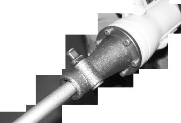
10 ESPAÑOL Componentes principales La numeración de los componentes está referida a la imagen de la he rramienta eléctrica en la página ilustrada. 1 Portabrocas 2 Portaútiles SDS-plus/SDS-max 3 Caperuza antipolvo 4 Casquillo de enclavamiento 5 Selector de sentido de giro 6 Tecla de enclavamiento del interruptor de conexión/desconexión 7 Interruptor de conexión/desconexión 8 Botón de desenclavamiento del mando desactivador de percusión y giro 9 Mando desactivador de percusión 10 Botón de ajuste RPM 11 Empuñadura adicional 12 Empuñadura 13 Asa transporte 14 Tuerca moleteada para asa de transporte 15 Bulón de fijación 16 Vástago del útil 17 Alojamiento del útil 18 Selector de posición del cincel 3.- Montaje HD21K, HD27K / HD27BK, HD28K, HD5K, HD5BK, HD50K, HD55K, HD3K, HD6K, HD45K, MH2K, MH6K, MH8K f Antes de cualquier manipulación en la herramienta eléctrica, sacar el enchufe de red de la toma de corriente Empuñadura adicional f Solamente utilice la herramienta eléctrica con la empuñadura adicional 11 montada. Giro de la empuñadura adicional La empuñadura adicional 11 puede girarse a cualquier posición para permitirle trabajar manteniendo una postura firme y cómoda. Afloje en sentido contrario a las agujas del reloj el mango de la empuñadura adicional 11 y gire ésta a la posición deseada. Seguidamente, apriete el mango en el sentido de las agujas del reloj para sujetar la empuñadura adicional 11. Observe que la abrazadera de la empuñadura adicional quede alojada en la ranura de la carcasa prevista para tal fin Cambio de útil La caperuza antipolvo 3 evita en gran medida que el polvo que se va produciendo al trabajar no logre penetrar en el portaútiles. Al montar el útil, preste atención a no dañar la caperuza antipolvo 3. f Haga sustituir de inmediato una caperuza antipolvo deteriorada. Se recomienda que este trabajo sea realizado por un servicio técnico. Montaje del útil SDS El portaútiles SDS le permite cambiar el útil de forma sencilla y cómoda sin precisar para ello una herramienta. Limpie primero y aplique a continuación una capa ligera de grasa al extremo de inserción del útil. Inserte girando el útil en el portaútiles hasta conseguir que éste quede sujeto automáticamente. Tire del útil para cerciorarse de que ha quedado correctamente sujeto. Condicionado por el sistema, el útil SDS puede moverse libremente. A ello se debe que se presente un error de redondez al girar en vacío. Esto no afecta para nada a la precisión del taladro realizado, ya que la broca se autocentra al taladrar. 10
11 ESPAÑOL 11 Desmontaje del útil SDS Empuje hacia atrás el casquillo de enclavamiento 4 y retire el útil Asa de transporte (HD15K / HD17K) Ud. puede abatir discrecionalmente el asa de transporte 13. Afloje la tuerca moleteada 14, gire el asa de transporte 13 en torno al eje del aparato a la posición deseada, y vuelva a apretar la tuerca moleteada 14. Vd. puede montar el asa de transporte 13 en una posición diferente. Para ello, desenrosque completamente la tuerca moleteada 14, y saque hacia arriba el tornillo de cabeza hexagonal. Saque lateralmente asa de transporte 13 y gire entonces 180 la pieza a la que iba sujeto. Monte el asa de transporte 13 siguiendo los pasos en orden inverso Cambio de útil (HD15K / HD17K/ MH2K / MH6K / MH8K) f Antes de cualquier manipulación en la herramienta eléctrica, sacar el enchufe de red de la toma de corriente. Limpie el vástago del útil 16 y aplique a continuación una capa ligera de grasa. Empuje hacia fuera el bulón de fijación 15 y gírelo 180 en sentido contrario a las agujas del reloj. Deje que el bulón de fijación 15 enclave nuevamente. Inserte hasta el tope el útil en el alojamiento del mismo. La ranura del vástago del útil 16 deberá mostrar hacia arriba según figura. Tire del útil para cerciorarse de que ha quedado correctamente sujeto. 4.- Operación Puesta en marcha f Observe la tensión de red! La tensión de la fuente de energía deberá coincidir con las indicaciones en la placa de características de la herramienta eléctrica. Las herramientas eléctricas marcadas con 230 V pueden funcionar también a 220 V. 11 Ajuste del modo de operación Con el selec tor Taladrar/taladrar con percusión 9 puede Ud. ajustar el modo de operación de la herramienta eléctrica. Para modificar el modo de operación, accione el botón de desenclavamiento 8 y gire el selector Taladrar/taladrar con percusión 9 a la posición deseada hasta enclavarlo de manera perceptible. Observación: Únicamente cambie el modo de operación estando desconectada la herramienta eléctrica! En caso contrario podría dañarse la herramienta eléctrica. Posición para Taladrar con percusión en hormigón o piedra. HD5K, HD5BK, MH6K: 8' Posición para Taladrar, sin percutir, en madera, metal, cerámica y plástico, así como para atornillar y para hacer roscas Posición para modificar la posición del cincel Posición para Cincelar HD5K, HD5BK, MH6K: 8' Cambio de la posición Cincelar - Vario-lock (HD9CK) El cincel puede ser posicionado en 12 ángulos. De esta manera, la posición de trabajo óptima se puede establecer para cada aplicación. Inserte el cincel en el portaherramientas - Empuje el anillo 18 hacia adelante y gire el cincel en la posición deseada. - Suelte el anillo 18 para bloquear la posición.
12 ESPAÑOL 12 Ajuste del sentido de giro Con el selector 5 puede invertirse el sentido de giro actual de la herramienta eléctrica. Esto no es posible, sin embargo, con el interruptor de conexión/desconexión 7 accionado. Giro a derechas: Gire hasta el tope, a ambos lados, el selector de sentido de giro 5 hacia la posición. Giro a izquierdas: Gire hasta el tope, a ambos lados, el selector de sentido de giro 5 hacia la posición. Al taladrar con o sin percusión, y al cincelar, ajuste siempre el sentido de giro a derechas. Conexión/desconexión Para conectar la herramienta eléctrica presionar el interruptor de conexión/desconexión 7. Para enclavar el interruptor de conexión/desconexión manténgalo accionado, y pulse además la tecla de enclavamiento 6. Para desconectar la herramienta eléctrica suelte el interruptor de conexión/desconexión 7. Si el interruptor de conexión/desconexión 7 estuviese enclavado, apriételo primero y suéltelo a continuación. Ajuste del nº de revoluciones/frecuencia de percusión Variando la presión ejercida sobre el interruptor de conexión/desconexión 7/10 puede Ud. regular de forma continua las revoluciones/nº de impactos de la herramienta eléctrica. Accionando ligeramente el interruptor de conexión/desconexión 7/10 se obtienen unas revoluciones/frecuencia de percusión reducida. Aumentando paulatinamente la presión se van aumentando en igual medida las revoluciones/ frecuencia de percusión. Embrague limitador de par f En caso de engancharse o bloquearse el útil se desacopla el husillo de la unidad de accionamiento. Debido a la elevada fuerza de reacción resultante, siempre sujete la herramienta eléctrica con ambas manos y trabaje sobre una base firme. f En caso de bloquearse el útil, desconectar la herramienta eléctrica y liberar el útil. Si el aparato se conecta estando bloqueado el útil de taladrar se producen unos pares de reacción muy elevados Instrucciones para la operación Modificación de la posición para cincelar El cincel SDS puede sujetarse en posiciones diferentes. Ello le permite adoptar en cada caso una posición de trabajo óptima. Monte el cincel en el portaútiles. Gire el mando desactivador de percusión y giro 8 Gire el portaútiles hasta conseguir la posición del cincel deseada. Gire el mando desactivador de percusión y giro 8 a la posición Cincelar. El portaútiles queda retenido entonces en esa posición. Para cincelar ajuste el sentido de giro a derechas. Conexión / desconexión: A Para la puesta en marcha de la herramienta eléctrica accionar y mantener en esa posición el interruptor de conexión/desconexión 6. Para desconectar la herramienta eléctrica soltar el interruptor de conexión/desconexión 6. Conexión / desconexión: B Para la puesta en marcha de la herramienta eléctrica, presione arriba ( I ) el interruptor de conexión/desconexión 6/7 hasta lograr enclavarlo. Para desconectar la herramienta eléctrica, presione abajo ( 0 ) el interruptor de conexión/desconexión 6/7 y suéltelo a continuación. 12
13 ESPAÑOL 13 A bajas temperaturas, la herramienta eléctrica deberá funcionar primero durante cierto tiempo hasta que alcance su pleno rendimiento de percusión/impacto. Ajuste del nº de revoluciones/frecuencia de percusión El regulador electrónico 10 permite preseleccionar de forma continua las revoluciones y la frecuencia de percusión para adaptarlas a los requerimientos de trabajo. La potencia máxima del martillo se alcanza colocando la rueda de ajuste 10 en la posición 6 (HD50K) Por motivos técnicos, la potencia del martillo se reduce en parte al trabajar a unas revoluciones menores. OPERACIÓN HD15K / HD17K Puesta en marcha f Observe la tensión de red! La tensión de la fuente de energía deberá coincidir con las indicaciones en la placa de características de la herramienta eléctrica. Las herramientas eléctricas marcadas con 230V pueden funcionar también a 220V. Conexión/desconexión Para la puesta en marcha de la herramienta eléctrica, presione hacia abajo el interruptor de nexión 6/7 conexión/desco- a la posición I. Para desconectar la herramienta eléctrica, presione hacia abajo el interruptor de conexión /desconexión 6/7 a la posición 0. A bajas temperaturas la herramienta eléctrica deberá funcionar primero cierto tiempo hasta que logre alcanzar su pleno rendimiento de percusión. Este tiempo puede reducirse si el útil montado en la herramienta eléctrica, estando ésta detenida, es golpeado verticalmente una vez contra el suelo Instrucciones para la operación 5.- Mantenimiento y servicio Mantenimiento y limpieza f Antes de cualquier manipulación en la herramienta eléctrica, sacar el enchufe de red de la toma de corriente. f Mantenga limpia la herramienta eléctrica y las rejillas de refrigeración para trabajar con eficacia y seguridad. f Haga sustituir de inmediato una caperuza antipolvo deteriorada. Se recomienda que este trabajo sea realizado por un servicio técnico. Limpie el portaútiles 2 después cada uso. Si el desgaste de las escobillas es excesivo, la herramienta eléctrica se desconecta automáticamente. La herramienta eléctrica deberá enviarse para su mantenimiento a uno de los servicios técnicos que se indican bajo el apartado Servicio técnico y asistencia al cliente. Afilado de los cinceles Reafile los cinceles con suficiente antelación, ya que solamente unos cinceles bien afilados le permiten obtener buenos resultados. Con ello se garantiza una gran longevidad de los útiles, además de unos buenos resultados en el trabajo. Reafilado Reafile los cinceles con muelas, p. ej. de corindón noble, bajo la aportación uniforme de agua. Valores orientativos al respecto se obtienen en la figura. Preste atención a que no se alcancen los colores de revenido en los filos, ya que ello mermaría la dureza del cincel ca ca Durante el trabajo sujete la herramienta eléctrica con ambas manos por la empuñadura 1 Para obtener una amortiguación máxima de los impactos, trabaje ejerciendo una presión moderada. 13
14 ESPAÑOL 14 Para forjar el cincel caliéntelo entre 850 a 1050 C (entre rojo claro y amarillo). Para templar el cincel caliéntelo a aprox. 900 C y enfríelo en baño de aceite. A continuación manténgalo en un horno durante aprox. una hora a 320 C (color de revenido azul claro). Si a pesar de los esmerados procesos de fabricación y control, la herramienta eléctrica llegase a averiarse, la reparación deberá encargarse a un servicio técnico autorizado para herramientas eléctricas Stayer. Para cualquier consulta o pedido de piezas de repuesto es imprescindible indicar el nº de artículo que figura en la placa de ca racterísticas de la herramienta eléctrica Declaración de conformidad Declaramos bajo nuestra responsabilidad, que el producto descrito bajo Datos técnicos está en conformidad con las normas o documentos normalizados siguientes: UNE EN :2010/A11:2011, UNE EN :2011, EN :2006, EN :2006, EN :1995+A1:2001+A2:2005, EN ISO 3744:1995 de acuerdo con las regulaciones 2004/108/CE, 2006/42/CE, 2000/14/CE Ramiro de la Fuente Director Manager Eliminación Recomendamos que las herramientas eléctricas, accesorios y embalajes se an sometidos a un proceso de recuperación que respete el medio ambiente. Sólo para los países de la UE: No arroje las herramientas eléctricas a la basura! Conforme a la Directriz Europea 2002/96/CE sobre aparatos eléctricos y electrónicos inservibles, tras su transposición en ley nacional, deberán acumularse por separado las herramientas eléctricas para ser sometidas a un reciclaje ecológico. Reservado el derecho de modificación. 14
15 ITALIANO Istruzioni di sicurezza specifiche per la macchina f Portare cuffie di protezione. L effetto del rumore può provocare la perdita dell udito. f Utilizzare le impugnature supplementari fornite insieme all elettroutensile. La perdita di controllo sull elettroutensile può comportare il peric olo di incidenti. f Al fine di rilevare linee di alimentazione nascoste, utilizzare adatte apparecchiature di ricerca oppure rivolgersi alla locale società erogatrice. Un contatto con linee elettriche può provocare lo sviluppo di incendi e di scosse elettriche. Danneggiando linee del gas si può creare il pericolo di esplosioni. Penetrando una tubazione dell acqua si provocano seri danni materiali oppure vi è il pericolo di provocare una scossa elettrica. f Quando si eseguono lavori in cui vi è pericolo che l accessorio impiegato possa arrivare a toccare cavi elettrici nascosti oppure anche il cavo elettrico della macchina stessa, tenere l elettroutensile afferrandolo sempre alle superfici di impugnatura isolate. Un contatto con un cavo elettrico mette sotto tensione anche le parti in metallo dell elettroutensile e provoca quindi una scossa elettrica. f Durante le operazioni di lavoro è necessario tenere l elettroutensile sempre con entrambe le mani ed adottare una posizione di lavoro sicura. Utilizzare con sicurezza l elettroutensile tenendolo sempre con entrambe le mani. f Assicurare il pezzo in lavorazione. Un pezzo in lavorazione può essere bloccato con sicurezza in posizione solo utilizzando un apposito dispositivo di serraggio oppure una morsa a vite e non tenendolo con la semplice mano. f Non lavorare mai materiali contenenti amianto. L amianto è ritenuto materiale cancerogeno. f Prendere dei provvedimenti appropriati in caso che durante il la voro dovessero svilupparsi polveri dannose per la salute, infiammabili oppure esplosive. Ad esempio: Alcune polveri sono considerate cancerogene. Portare una maschera di protezione contro la polvere ed utilizzare, se collegabile, un sistema di aspirazione polvere/aspirazione trucioli. f Mantenere pulita la propria zona di lavoro. Miscele di materiali di diverso tipo possono risultare particolarmente pericolose. La polvere di metalli leggeri può essere infiammabile ed esplosiva. f Prima di posare l elettroutensile, attendere sempre fino a quando si sarà fermato completamente. L accessorio può incepparsi e comportare la perdita di controllo dell elettroutensile. f Mai utilizzare l elettroutensile con un cavo danneggiato. Non toccare il cavo danneggiato ed estrarre la spina di rete in caso che si dovesse danneggiare il cavo mentre si lavora. Cavi danneggiati aumentano il rischio di una scossa di corrente elettrica. 2.- Descrizione del funzionamento Leggere tutte le avvertenze di pericolo e le istruzioni operative. In caso di mancato rispetto delle avvertenze di pericolo e delle istruzioni operative si potrà creare il pericolo di scosse elettriche, incendi e/o incidenti gravi. Si prega di aprire la pagina ribaltabile su cui si trova raffigurata schematicamente la macchina e lasciarla aperta mentre si legge il manuale delle Istruzioni per l uso Uso conforme alle norme HD21K, HD27K / HD27BK, HD28K, HD5K, HD5BK, HD50K, HD55K, MH6K L elettroutensile è ideale per la foratura a martello in calcestruzzo, mattoni e roccia (Tranne HD21). Lo stesso è anche adatto per forare senza percussione nel legno, metallo, ceramica e materiale sintetico. Elettroutensili con regolazione elettronica e rotazione destrorsa/sinistrorsa sono adatti anche per avvitare e filettare. 15
16 ITALIANO 16 HD15K, HD17K, HD9BK, HD10K, MH8K L elettroutensile è idoneo per pesanti lavori di demolizione e di scalpellatura e, utilizzando rispettivi accessori opzionali, anche per operazioni di conficcamento e di costipazione Componenti illustrati La numerazione dei componenti illustrati si riferisce all illustrazione dell elettroutensile che si trova sulla pagina con la rappresentazione grafica. 1 Mandrino 2 Portautensili SDS-plus/ SDS-max 3 Protezione antipolvere 4 Mandrino di serraggio 5 Commutatore del senso di rotazione 6 Tasto di bloccaggio per interruttore avvio/arresto 7 Interruttore di avvio/arresto 8 Tasto di sbloccaggio per interruttore arresto rotazione/percussione 9 Interruttore arresto rotazione/percussione 10 Tasto per la regolazione rpm 11 Impugnatura supplementare 12 Impugnatura 13 Maniglia 14 Dado zigrinato per maniglia 15 Bullone di bloccaggio 16 Gambo dell utensile 17 Mandrino portautensile 18 Scalpello posizione del selettore 3.- Montaggio HD21K, HD27K / HD27BK, HD28K, HD5K, HD5BK, HD50K, HD55K, HD3K, HD6K, HD45K, MH2K, MH6K, MH8K f Prima di qualunque intervento sull elettroutensile estrarre la spina di rete dalla presa Impugnatura supplementare f Utilizzare il Vostro elettroutensile soltanto con l impugnatura supplementare 11. Regolazione dell impugnatura supplementare L impugnatura supplementare 11 può essere spostata liberamente e regolata in modo da permettere di prendere una posizione di lavoro di assoluta maneggevolezza. Girare la maniglia inferiore dell impugnatura supplementare 11 in senso antiorario e spostare l impugnatura supplementare 11 alla posizione richiesta. Avvitare dunque la maniglia inferiore dell impugnatura supplementare 11 di nuovo bene in senso orario. Prestare attenzione affinchè il nastro di serraggio dell impugnatura supplementare si trovi nella scanalatura prevista allo scopo sulla carcassa Cambio degli utensili La protezione antipolvere 3 ha la funzione di impedire in larga misura che la polvere provocata forando possa arrivare a penetrare nel mandrino portautensile durante la fase di funzionamento. Applicando l accessorio, attenzione a non danneggiare la protezione antipolvere 3. f Una protezione antipolvere danneggiata deve essere sostituita immediatamente. Si consiglia di affidare l operazione ad un Centro di Assistenza Clienti. Montaggio dell utensile accessorio SDS Con il mandrino portapunta SDS è possibile sostituire l utensile accessorio in modo facile e comodo senza l impiego di ulteriori attrezzi. Pulire il gambo dell utensile accessorio ed applicarvi un leggero strato di grasso. Applicare l accessorio nel mandrino portautensile ruotandolo fino a farlo sarà arrivato a bloccarsi autonomamente. Controllare il bloccaggio tirando l accessorio. Il sistema dell accessorio SDS è un sistema mobile. In questo modo si ha una deviazione della rotazione nel corso del funzionamento a vuoto. Questo fatto non ha nessun effetto sulla precisione della foratura perché la centratura del foro avviene automaticamente nel corso della foratura. 16
17 ITALIANO 17 Smontaggio dell utensile accessorio SDS Spingere il mandrino di serraggio 4 all indietro ed estrarre l accessorio Maniglia (HD15K / HD17K) La maniglia 13 può essere spostata liberamente. Allentare il dado zigrinato 14, ribaltare la maniglia 13 attorno all asse della macchina portandola alla posizione richiesta ed avvitare di nuovo bene il dado zigrinato 14 La maniglia 3 può essere montata in un altra posizione. A tal fine, svitare completamente il dado zigrinato 14 ed estrarre quindi la vite a testa esagonale completamente tirandola verso l alto. Tirare la maniglia 13 lateralmente e ribaltare di 180 il particolare di serraggio rimanente. Montare la maniglia 13 seguendo l ordine inverso. Per modificare il modo operativo premere il tasto di sbloccaggio 8 e ruotare il selettore «foratura /foratura a martello» 9 nella posizione desiderata fino a quando lo stesso non scatta in posizione in modo percettibile. Nota bene: Modificare il modo operativo solo quando l elettroutensile è spento! In caso contrario l elettroutensile può subire dei danni. Posizione per forature battenti nel calcestruzzo oppure materiale pietroso HD5K, HD5BK, MH6K: Cambio degli utensili (HD15K / HD17K/ MH2K / MH6K / MH8K) f Prima di qualunque intervento sull elettroutensile estrarre la spina di rete dalla presa. Pulire il gambo dell utensile 16 ed applicarvi un leggero strato di grasso. Estrarre completamente il bullone di bloccaggio 15 e ruotarlo di 180 in senso antiorario. Far scattare di nuovo in posizione il bullone di bloccaggio 15 Spingere l accessorio impiegato fino alla battuta nel mandrino portautensile. La scanalatura del gambo dell utensile 16 deve indicare verso l alto come indicato nell illustrazione. Controllare il bloccaggio tirando l utensile accessorio. 4.- Uso Messa in funzione f Osservare la tensione di rete! La tensione della rete deve corrispondere a quella indicata sulla targhetta dell elettroutensile. Gli elettroutensili con l indicazione di 230 V possono essere collegati anche alla rete di 220 V. Regolazione del modo operativo Con il selettore «foratura/fora tura a martello» 9 scegliere il modo operativo dell elettroutensile. Posizione per foratura senza percussione nel legname, metallo, ceramica e materiale sintetico ed anche per avvitatura e filettatura Posizione per correggere la posizione di scalpellatura Posizione per scalpellatura HD5K, HD5BK, MH6K: 8 Riposizionare Scalpellatura Vario-lock (HD9CK) Lo scalpello 12 può essere posizionata ad angoli. Così, la posizione di lavoro ottimale può essere impostato per ogni applicazione. Inserire lo scalpello nel portautensili - Spingere l'anello 18 in avanti e ruotare lo scalpello nella posizione desiderata. - Rilasciare il anello 18 per bloccare la posizione. 17
18 ITALIANO 18 Impostazione del senso di rotazione Con il commutatore del senso di rotazione 5 è possibile modificare il senso di rotazione dell elettroutensile. Comunque, ciò non è possibile quando l interruttore di avvio/arresto 7 è premuto. Rotazione destrorsa: Ruotare il commutatore del senso di rotazione 5 su entrambi i lati fino all arresto in posizione. Rotazione sinistrorsa: Ruotare il commutatore del senso di rotazione 5 su entrambi i lati fino all arresto in posizione. Per operazioni di foratura e scalpellatura, regolare il senso di rotazione sempre su rotazione destrorsa. Accendere/spegnere Per accendere l elettroutensile premere l interruttore di avvio/arresto 7. Per bloccare l interruttore avvio/arresto, tenerlo premuto e premere ulteriormente il tasto di bloccaggio 6. Per spegnere l elettroutensile rilasciare l interruttore di avvio/arresto 7. In caso di interruttore di avvio/arresto 7 bloccato, premerlo prima e rilasciarlo poi subito. Regolazione del numero di giri/numero di colpi È possibile regolare a variazione continua la velocità/frequenza di colpi dell elettroutensile in funzione operando con la pressione che si esercita sull interruttore avvio/arresto 7/10. Esercitando una leggera pressione sull interruttore di avvio/arresto 7/10 si ha una riduzione della velocità/numero frequenza colpi. Aumentando la pressione si aumenta la velocità/numero frequenza colpi. Frizione di sicurezza contro il sovraccarico f La trasmissione all alberino filettato si blocca se l accessorio si inceppa oppure resta bloccato. Per via delle rilevanti forze che si sviluppano mentre si opera in questo modo, afferrare sempre l elettroutensile con entrambe le mani ed assicurarsi una sicura posizione operativa. f Se l elettroutensile si blocca, spegnere l elettroutensile e sbloccare l accessorio impiegato. Avviando la macchina con la punta utensile bloccata si provocano alti momenti di reazione! Indicazioni operative Cambio della posizione scalpellatura Si ha la possibilità di bloccare lo scalpello SDS in posizioni. In questo modo è possibile prendere rispettivamente la posizione di lavoro ottimale. Applicare lo scalpello nel mandrino portautensile. Ruotare l interruttore arresto rotazione/percussione nella posizione Ruotare il mandrino portautensile sulla posizione di scalpellatura richiesta. Ruotare l interruttore arresto rotazione/percussione 8 nella posizione «Scalpellatura». In questo modo il portautensili è bloccato. Per lavori di scalpellatura regolare il senso di rotazione su rotazione destrorsa. Accensione/spegnimento: A Per accendere l elettroutensile premere l interruttore di avvio/arresto 4 e tenerlo premuto. Per spegnere l elettroutensile rilasciare di nuovo l interruttore di avvio/arresto 4. Accensione/spegnimento: B Per la messa in funzione dell elettroutensile premere l interruttore di avvio/arresto 6/7 in alto (I) fino a quando lo stesso si blocca. Per lo spegnimento dell elettroutensile premere l interruttore di avvio/arresto 6/7 in basso ( 0) e rilasciarlo. In caso di temperature basse, l elettroutensile raggiunge solo dopo un certo tempo la potenza battente/potenza di percussione completa.
19 ITALIANO 19 Regolazione del numero di giri/numero di colpi Tramite l elettronica di regolazione 10 è possibile preselezionare in continuo il numero di giri e la frequenza dei colpi in funzione del materiale in lavorazione. La potenza massima di percussione si raggiunge quando la rotellina per la selezione del numero di giri 10 si trova in posizione «6» HD50K. In caso di numeri di giri ridotti, per motivi tecnici si riduce anche la potenza di percussione. Uso HD15K / HD17K Messa in funzione f Osservare la tensione di rete! La tensione della rete deve corrispondere a quella indicata sulla targhetta de ll elettroutensile. Gli elettroutensili con l indicazione di 230 V possono essere collegati anche alla rete di 220 V. Accendere/spegnere Per accendere l elettroutensile, spingere in avanti l interruttore di avvio/arresto 6/7 in posizione «I». Per spegnere l elettroutensile, ribaltare l interruttore di avvio/arresto 6/7 in posizione «0». In caso di temperature basse l elettroutensile raggiunge la propria completa potenza del colpo soltanto dopo un certo periodo di tempo. Tale periodo di avviamento può essere ridotto battendo una volta sul pavimento l utensile accessorio inserito nell elettroutensile Indicazioni operative Lavorando, impugnare l elettroutensile alla maniglia 1 con entrambe le mani. Per raggiungere la maggiore possibile ammortizzazione del colpo, operare esercitando soltanto una pressione media. 5.- Manutenzione ed assistenza Manutenzione e pulizia f f Prima di qualunque intervento sull elettroutensile estrarre la spina di rete dalla presa. Per poter garantire buone e sicure operazioni di lavoro, tenere sempre puliti l elettroutensile e le prese di ventilazione. f Una protezione antipolvere danneggiata deve essere sostituita immediatamente. Si consiglia di affidare l operazione ad un Centro di Assistenza Clienti. Pulire il portautensili 2 dopo ogni utilizzo. Quando le spazzole di carbone sono usurate, l elettroutensile si spegne automaticamente. Per le operazioni dimanutenzione l elettroutensile deve essere spedito al Centro di Assistenza Clienti. Per l indirizzo, vedereparagrafo «Servizio postvendita». Affilare gli scalpelli Solo con attrezzi di scalpellatura bene affilati si possono raggiungere buoni risultati. Provvedere dunque ad affilarli sempre a tempo debito. In questo modo si garantisce una lunga durata degli attrezzi e buoni risultati delle operazioni. Riaffilatura Smerigliare gli attrezzi di scalpellatura utilizzando mole abrasive, p. es. corindone prezioso, mantenendo sempre costante l aggiunta di acqua. Nella figura si trovano valori indicativi per questa operazione. Accertarsi che sui taglienti non si arrivi alla presenza di colore di rinvenimento; ciò comprometterebbe la durezza degliattrezzi di scalpellatura ca Per operazioni di fucinatura surriscaldare lo scalpello fino a C (rosso chiaro fino a giallo). Per operazioni di tempratura surriscaldare lo scalpello fino a circa 900 C e temprarein bagno d olio. Al termine dell operazione, lasciarlo nel forno per ca. un ora a 320 C (colore di rinvenimento blu chiaro). Se nonostante gli accurati procedimenti di produzione e di controllo l elettroutensile dovesse guastarsi, la riparazione va fatta effettuare da un punto di assistenza autorizzato per gli elettroutensili Stayer. In caso di richieste o di ordinazione di pezzi di ricambio, comunicare sempre il codice prodotto riportato sulla targhetta di fabbricazione dell elettroutensile! ca
20 ITALIANO Smaltimento Avviare ad un riciclaggio rispettoso dell ambiente gli imballaggi, gli elettroutensili e gli accessori dismessi. Solo per i Paesi della CE: Non gettare elettroutensili dismessi tra i rifiuti domestici! Conformemente alla norma della direttiva CE 2002/96 sui rifiuti di apparecchiature elettriche ed elettroniche (RAEE) ed all attuazione del recepimento nel diritto nazionale, gli elettroutensili diventati inservibili devono essere raccolti separatamente ed essere inviati ad una utilizzazione ri ecologica. Con ogni riserva di modifiche tecniche Dichiarazione di conformità Dichiariamo sotto la nostra esclusiva responsabilità, che questo prodotto è conforme alle norme o ai documenti normativi seguenti: UNE EN :2010/A11:2011, UNE EN :2011, EN :2006, EN :2006, EN :1995+A1:2001+A2:2005, EN ISO 3744:1995 in base alle pre-scrizioni delle direttive 2004/108/CE, 2006/42/CE, 2000/14/CE. Ramiro de la Fuente Director Manager 20
21 ENGLISH Machine-specific Safety Warnings f Wear hearing protection. Exposure to noise can cause hearing loss. f Always use the auxiliary handle supplied with the machine. Loss of control can cause personal injury. f Use suitable detectors to determine if utility lines are hidden in the work area or call the local utility company for assistance. Contact with electric lines can lead to fire and electric shock. Damaging a gas line can lead to explosion. Penetrating a water line causes property damage or may cause an electric shock. f Hold the power tool only by the insulated gripping surfaces when performing an operation where the cutting tool may contact hidden wiring or its own cord. Contact with a live wire will also make exposed metal parts of the power tool live and shock the operator. f When working with the machine, always hold it firmly with both hands and provide for a secure stance. The power tool is guided more secure with both hands. f Secure the workpiece. A workpiece clamped with clamping devices or in a vice is held more secure than by hand. f Do not work materials containing asbestos. Asbestos is considered carcinogenic. f Take protective measures when dust can develop during working that is harmful to one s health, combustible or explosive. Example: Some dusts are regarded as carcinogenic. Wear a dust mask and work with dust/chip extraction when connectable. Blends of mate- f Keep your workplace clean. rials are particularly dangerous. Dust from light alloys can burn or explode. f Always wait until the machine has come to a complete stop before placing it down. The tool insert can jam and lead to loss of control over the power tool. f Never use the machine with a damaged cable. Do not touch the damaged cable and pull the mains plug when the cable is damaged while working. Damaged cables increase the risk of an electric shock. 2.- Functional Description Read all safety warnings and all instructions. Failure to follow the warnings and instructions may result in electric shock, fire and/or serious injury. While reading the operating instructions, unfold the graphics page for the machine and leave it open Intended Use HD21K, HD27K / HD27BK, HD28K, HD5K, HD5BK, HD50K, HD55K, MH6K The machine is intended for hammer drilling in concrete, brick and stone (Except HD21). It is also suitable for drilling without impact in wood, metal, ceramic and plastic. Machines with electronic control and right/left rotation are also suitable for screwdriving and thread cutting. HD15K, HD17K, HD9BK, HD10K, MH8K The machine is intended for heavy chiselling and demolition work as well as for driving in and com- pacting with the appropriate accessories Product Features The numbering of the product features refers to the illustration of the machine on the graphics 1 Chuck 2 SDS-plus/SDS-max tool holder 3 Dust protection cap 4 Locking sleeve 5 Rotational direction switch 6 Lock-on button for On/Off switch 7 On/Off switch 8 Release button for mode selector switch 9 Mode selector switch 10 Button for RPM adjustment 11 Auxiliary handle 21
22 ENGLISH Handle Carrying handle Knurled nut for carrying handle Limit bolt Tool shank 17 Tool holder 18 Chisel position selector 3.- Assembly HD21K, HD27K / HD27BK, HD28K, HD5K, HD5BK, HD50K, HD55K, HD3K, HD6K, HD45K, MH2K, MH6K, MH8K f Before any work on the machine itself, pull the mains plug Auxiliary Handle f Operate your machine only with the auxiliary handle 11. Rotating the Auxiliary Handle The auxiliary handle 11 can be set to any position for a secure and low-fatigue working posture. Turn the bottom part of the auxiliary handle 11 in counterclockwise direction and swivel the auxiliary handle 11 to the desired position. Then retighten the bottom part of the auxiliary handle 11 by turning in clockwise direction. Pay attention that the clamping band of the auxiliary handle is positioned in the groove on the housing as intended for Changing the Tool The dust protection cap 3 largely prevents the entry of drilling dust into the tool holder during operation. When inserting the tool, take care that the dust protection cap 3 is not damaged. f A damaged dust protection cap should be changed immediately. We recommend having this carried out by an after-sales service. Inserting SDS-plus Drilling Tools The SDS drill chuck allows for simple and convenient changing of drilling tools without the use of additional tools. Clean and lightly grease the shank end of the tool. Insert the tool in a twisting manner into the tool holder until it latches itself. Check the latching by pulling the tool. As a requirement of the system, the SDS drilling tool can move freely. This causes a certain radial run-out at no-load, which has no effect on the accuracy of the drill hole, as the drill bit centres itself upon drilling. Removing SDS Drilling Tools Push back the locking sleeve 4 and remove the tool Carrying Handle (HD15K / HD17K) The carrying handle 13 can be turned to any position. Loosen the knurled nut 14, turn the carrying handle 13 around the machine axis to the desired position and tighten the knurled nut 14 again. The carrying handle 13can also be mounted facing to the other side. Completely unscrew the knurled nut 14 and then pull out the hexagon bolt upward. Pull off the carrying handle 13 to the side and tilt the remaining clamping element by 180. Mount the carrying handle 13 in reverse order Changing the Tool (HD15K / HD17K/ MH2K / MH6K / MH8K) f Before any work on th e machine itself, pull the mains plug. Clean the tool shank 16 and apply a light coat of grease. Pull out the lock bolt 15 and turn it 180 in anticlockwise direction. Allow the lock bolt 15 to latch again. Insert the tool into the tool holder to the stop. The groove of the tool shank 16 must face upward as shown in the figure. Check the latching by pulling the tool. 22
23 ENGLISH Operation Starting Operation f Observe correct mains voltage! The voltage of the power source must agree with the voltage specified on the nameplate of the machine. Power tools marked with 230 V can also be operated with 220 V. Setting the Operating Mode With the selector switch for drilling/hammer drilling 9, the operating mode of the machine is selected. To change the operating mode, press the release button 8 and turn the drilling/hammer drilling selector switch 9 to the desired position until it can be heard to latch. Note: Only change the mode of operation while disconnected from the machine! Otherwise you may damage the machine. Position for hammer drilling in concrete or stone HD5K, HD5BK, MH6K: 8' Position for drilling without impact in wood, metal, ceramic and plastic as well as for screwdriving and thread cutting. Position for adjustment of the chiseling position Position for chiselling HD5K, HD5BK, MH6K: 8' Reposition Chiseling Vario-lock (HD9CK) The chisel 12 may be positioned at angles. Thus, the optimal working position can be set for each application. Insert the chisel in the tool holder - Push the ring 18 forward and turn the chisel in the desired position. - Release the ring 18 to lock the position. Reversing the Rotational Direction The rotational direction switch 5 is used to reverse the rotational direction of the machine. However, this is not possible with the On/Off switch 7 actuated. Right rotation: Turn the selector switch for drilling/hammer drilling 5 on both sides to the stop in the position. Left rotation: Turn the selector switch for drilling/hammer drilling 5 on both sides to the stop in the position. Set the direction of rotation for hammer drilling, drilling and chiselling always to right rotation. Switching On and Off To start the machine, press the On/Off switch 7. To lock the On/Off switch, keep it pressed and additionally push the lock-on button 6. To switch off the machine, release the On/Off switch 7. When the On/Off switch 7 is locked, press it first and then release it. Setting the Speed/Impact Rate The speed/impact rate of the switched on power tool can be variably adjusted, depending on how far the On/Off switch 7/10 is pressed. Light pressure on the On/Off switch 7/10 results in low speed/impact rate. Further pressure on the switch increases the speed/impact rate. Safety Clutch f If the tool insert becomes caught or jammed, the drive to the drill spindle is interrupted. Because of the forces that occur, always hold the power tool firmly with both hands and provide for a secure stance. 23
24 ENGLISH 24 f If the power tool jams, switch the machine off and loosen the tool insert. When switching the machine on with the drilling tool jammed, high reaction torques can occur Working Advice Changing the Chiselling Position The chisel SDS can be locked in different positions. In this manner, the optimum working position can be set for each application. Insert the chisel into the tool holder. Turn the mode selector switch 8 Turn the tool holder to the desired chiselling position. Turn the mode selector switch 8 to the chiseling position. The tool holder is now locked. For chiselling, set the rotation direction to right rotation. Switching On/Off: A To start the machine, press the On/Off switch 6 and keep it depressed. To switch off the machine, release the On/Off switch 6. Switching On/Off: B The maximum hammering capacity is achieved when the thumbwheel 10 is set to position 6. (HD50K) For lower speed settings, the hammering capacity is lower due to technical reasons. Operation HD15K / HD17K Starting Operation f Observe correct mains voltage! The voltage of the power source must agree with the voltage specified on the nameplate of the machine. Power tools marked with 230V can also be operated with 220V. Switching On and Off To start the machine, push the On/Off switch 6/7 to the I position. To switch off the machine, push the On/Off switch 6/7 to the O position. For low temperatures, the machine reaches the full impact rate only after a certain time. This start-up time can be shortened by striking the chisel in the machine against the floor one time Operating Instructions While working, hold the power tool with both hands by the handle 1. For the highest possible impact damping, work only with moderate pressure. To start the machine, press the On/Off switch 6/7 at the top ( I ) until it locks. To switch off the machine, press the On/Off switch 6/7 at the bottom (O) and release it. For low temperatures, the power tool reaches the full hammer/impact capacity only after a certain time. Setting the Speed/Impact Rate The electronic control 10 enables stepless speed and impact preselection in accordance with the material to be worked. 5.- Maintenance and Service Maintenance and Cleaning f Before any work on the machine itself, pull the mains plug. f For safe and proper working, always keep the machine and ventilation slots clean. f A damaged dust protection cap should be changed immediately. We recommend having this carried out by an after-sales service. Clean the tool holder 2 each time after using. 24
25 ENGLISH 25 WARNING! Important instructions for connecting a new 3-pin plug to the 2-wire cable. The wires in the cable are coloured according to the following code: Do not connect the blue or brown wire to the earth terminal of the plug. Important: If for any reason the moulded plug is removed from the cable of this power tool, it must be disposed of safely. When the carbon brushes wear below acceptable service tolerances, the machine will automatically cut out. The machine must be sent to customer service for maintenance for address, see the Service and Customer Assistance section. Sharpening Chisels Good results are only achieved with sharp chisels; therefore, sharpen the chiselling tools in good time. This ensures a long service life of the tools and good working performance. Re-sharpening Sharpen chiselling tools using grinding wheels (e.g.ceramic bonded corundum wheel) with a steady supply of water. Reference values are shown in the figure. Take care that no annealing coloration appears on the cutting edges; this impairs the hardness of the chiselling tools ca ca For forging, heat the chisel to between 850ºC and 1050 C (bright red to yellow). For hardening, heat the chisel to approx. 900 C and quench in oil. Then anneal in an oven for approx. one hour at 320 C (annealing colour = light blue). If the machine should fail despite the care taken in manufacturing and testing procedures, repair should be carried out by an after-sales service centre for Stayer power tools. In all correspondence and spare parts order, please always include the article number given on the type plate of the machine Disposal The machine, accessories and packaging should be sorted for environmental-friendly recycling. Only for EC countries: Do not dispose of power tools into household waste! According the European Guideline 2002/96/EC for Waste Electrical and Electronic Equipment and its implemen-tation into national right, power tools that are no longer usable must be collected separately and disposed of in an environmentally correct manner. Subject to change without notice Declaration of Conformity We declare under our sole responsibility that this product is in conformity with the following standards or standardization documents: UNE EN :2010/A11:2011, UNE EN :2011, EN :2006, EN :2006, EN :1995+A1:2001+A2:2005, EN ISO 3744:1995 according to the provisions of the directives 2004/108/EC, 2006/42/EC, 2000/14/EC Ramiro de la Fuente Director Manager 25
ES IT GB DE FR P TR GR
 ES IT GB DE FR P TR GR Manual de instrucciones Istruzioni d uso Operating instructions Bedienungsanleitung Instructions d emploi Manual de instruções Kullanma Kιlavuzu Oδηγία χειρισµού HD3K - HD4BK HD21K
Περιεχόμενα / Contents
 Aερόθερμo / Fan Heater PTC-906 Περιεχόμενα / Contents GR... Σελίδες 3-8 EN... Pages 9-11 2 GR Ευχαριστούμε που επιλέξατε μια συσκευή της γκάμας θερμαντικών IZZY. Σημαντικές Οδηγίες Ασφαλείας Τα Μέρη της
!Stato di tensione triassiale!stato di tensione piano!cerchio di Mohr
 !Stato di tensione triassiale!stato di tensione piano!cerchio di Mohr Stato di tensione F A = F / A F Traione pura stato di tensione monoassiale F M A M Traione e torsione stato di tensione piano = F /
MS SERIES MS DESK TOP ENCLOSURE APPLICATION EXAMPLE FEATURE. Measuring instruments. Power supply equipments
 MS SERIES MS DESK TOP ENCLOSURE FEATURE Available in 176 sizes. Screws are not appeared on the surface. Usable as rack mount case with optinal mounting bracket. There are no ventilation hole for cover
Capacitors - Capacitance, Charge and Potential Difference
 Capacitors - Capacitance, Charge and Potential Difference Capacitors store electric charge. This ability to store electric charge is known as capacitance. A simple capacitor consists of 2 parallel metal
NMBTC.COM /
 Common Common Vibration Test:... Conforms to JIS C 60068-2-6, Amplitude: 1.5mm, Frequency 10 to 55 Hz, 1 hour in each of the X, Y and Z directions. Shock Test:...Conforms to JIS C 60068-2-27, Acceleration
MSN DESK TOP ENCLOSURE WITH STAND / CARRYING HANDLE
 MSN SERIES MSN DESK TOP ENCLOSURE WITH STAND / CARRYING HANDLE W H FEATURE Available in 176 sizes. Stand / carrying handle can be adjusted in 30 degree. Maximum load is kg. There are no ventilation hole
ΟΔΗΓΙΕΣ ΧΡΗΣΗΣ USE INSTRUCTIONS
 ΟΔΗΓΙΕΣ ΧΡΗΣΗΣ USE INSTRUCTIONS ΤΗΛΕΦΩΝΟ ΜΕ ΑΝΑΓΝΩΡΙΣΗ ΚΛΗΣΗΣ /CORDED PHONE WITH CALLER ID ΜΟΝΤΕΛΟ/MODEL: TM09-448 DC48V Παρακαλούμε διαβάστε προσεκτικά όλες τις οδηγίες χρήσης πριν την χρήση της συσκευής
the total number of electrons passing through the lamp.
 1. A 12 V 36 W lamp is lit to normal brightness using a 12 V car battery of negligible internal resistance. The lamp is switched on for one hour (3600 s). For the time of 1 hour, calculate (i) the energy
Operating Instructions and Parts Manual 14-inch Woodworking Band Saw Models JWBS-14SF and JWBS-14SF-3
 Operating Instructions and Parts Manual 14-inch Woodworking Band Saw Models JWBS-14SF and JWBS-14SF-3 Model #714500 shown JET 427 New Sanford Road LaVergne, Tennessee 37086 Part No. M-714500 Ph.: 800-274-6848
Catálogodegrandespotencias
 www.dimotor.com Catálogogranspotencias Índice Motores grans potencias 3 Motores asíncronos trifásicos Baja Tensión y Alta tensión.... 3 Serie Y2 Baja tensión 4 Motores asíncronos trifásicos Baja Tensión
OUR PRODUCT RANGE. www.rakson.gr
 ΤΑ ΑΛΛΑ ΕΙ Η ΠΡΟΪΟΝΤΑ ΜΑΣ ΜΕΤΑΣΧΗΜΑΤΙΣΤΕΣ ΚΟΥ ΟΥΝΙΩΝ ΚΟΥ ΟΥΝΙΑ ΜΠΟΥΤΟΝ ΚΟΥ ΟΥΝΙΩΝ ΑΥΤΟΜΑΤΟΙ ΚΛΙΜΑΚΟΣΤΑΣΙΟΥ ΚΛΕΙ ΑΡΙΕΣ ΑΝΙΧΝΕΥΤΕΣ ΚΙΝΗΣΗΣ ΣΥΣΤΗΜΑΤΑ ΕΠΙΚΟΙΝΩΝΙΑΣ Θυροτηλεοράσεις Θυροτηλέφωνα Ενδοεπικοινωνίες
Instruction Execution Times
 1 C Execution Times InThisAppendix... Introduction DL330 Execution Times DL330P Execution Times DL340 Execution Times C-2 Execution Times Introduction Data Registers This appendix contains several tables
Math 6 SL Probability Distributions Practice Test Mark Scheme
 Math 6 SL Probability Distributions Practice Test Mark Scheme. (a) Note: Award A for vertical line to right of mean, A for shading to right of their vertical line. AA N (b) evidence of recognizing symmetry
UDZ Swirl diffuser. Product facts. Quick-selection. Swirl diffuser UDZ. Product code example:
 UDZ Swirl diffuser Swirl diffuser UDZ, which is intended for installation in a ventilation duct, can be used in premises with a large volume, for example factory premises, storage areas, superstores, halls,
Operating Instructions and Parts Manual 14-inch Woodworking Band Saw Models JWBS-14SF and JWBS-14SF-3
 Operating Instructions and Parts Manual 14-inch Woodworking Band Saw Models JWBS-14SF and JWBS-14SF-3 Model #714500 shown JET 427 New Sanford Road LaVergne, Tennessee 37086 Part No. M-714500 Ph.: 800-274-6848
MODEL D25-42 D30-42 DIESEL PILE HAMMER SPARE PARTS BOOK
 MODEL D25-42 D30-42 DIESEL PILE HAMMER SPARE PARTS BOOK Corporate Office 7032 S. 196th Street Kent, WA, USA 98032 Tel: 1-800-248-8498 Tel: 1-253-872-0141 Fax: 1-253-872-8710 2 No. Parts-No. Description
(REV:01) RYOBI 48 Volt Lawn Mower Model No. RY14110 Replacement Parts List
 RYOBI 48 Volt Lawn Mower Model No. RY14110 Replacement Parts List") 9800-86 2-0-0 (REV:0) RYOBI 48 Volt Lawn Mower Model No. RY0 Replacement Parts List RYOBI RY0 48 volt lawn mower 3 38 39 44 39 36 34 36 42 38 39 3 4 37 34 3 43 2 32 0 8 9 2 4 33 8 7 6 3 6 7 22 8 20 3 30
9800-86 2-0-0 (REV:0) RYOBI 48 Volt Lawn Mower Model No. RY0 Replacement Parts List RYOBI RY0 48 volt lawn mower 3 38 39 44 39 36 34 36 42 38 39 3 4 37 34 3 43 2 32 0 8 9 2 4 33 8 7 6 3 6 7 22 8 20 3 30
Smaller. 6.3 to 100 After 1 minute's application of rated voltage at 20 C, leakage current is. not more than 0.03CV or 4 (µa), whichever is greater.
, whichever is greater.") Low Impedance, For Switching Power Supplies Low impedance and high reliability withstanding 5000 hours load life at +05 C (3000 / 2000 hours for smaller case sizes as specified below). Capacitance ranges
Low Impedance, For Switching Power Supplies Low impedance and high reliability withstanding 5000 hours load life at +05 C (3000 / 2000 hours for smaller case sizes as specified below). Capacitance ranges
Stato di tensione triassiale Stato di tensione piano Cerchio di Mohr
 Stato di tensione triassiale Stato di tensione iano Cerchio di Mohr Stato di tensione F A = F / A F Traione ura stato di tensione monoassiale F M A M Traione e torsione stato di tensione iano = F / A =
(REV:01) RYOBI 48 Volt Lawn Mower Model No. RY14110A Replacement Parts List
 RYOBI 48 Volt Lawn Mower Model No. RY14110A Replacement Parts List") 9000-7 9-- (REV:0) RYOBI 4 Volt Lawn Mower Model No. RY0A Replacement Parts List RYOBI RY0A 4 VOLT LAWN MOWER 3 3 39 44 39 3 34 3 42 3 39 3 4 37 34 3 43 2 0 37 2 33 32 3 9 7 22 30 4 7 3 20 9 3 2 2 27 2
9000-7 9-- (REV:0) RYOBI 4 Volt Lawn Mower Model No. RY0A Replacement Parts List RYOBI RY0A 4 VOLT LAWN MOWER 3 3 39 44 39 3 34 3 42 3 39 3 4 37 34 3 43 2 0 37 2 33 32 3 9 7 22 30 4 7 3 20 9 3 2 2 27 2
Precision Metal Film Fixed Resistor Axial Leaded
 Features EIA standard colour-coding Non-Flame type available Low noise and voltage coefficient Low temperature coefficient range Wide precision range in small package Too low or too high ohmic value can
Thin Film Chip Resistors
 FEATURES PRECISE TOLERANCE AND TEMPERATURE COEFFICIENT EIA STANDARD CASE SIZES (0201 ~ 2512) LOW NOISE, THIN FILM (NiCr) CONSTRUCTION REFLOW SOLDERABLE (Pb FREE TERMINATION FINISH) Type Size EIA PowerRating
την..., επειδή... Se usa cuando se cree que el punto de vista del otro es válido, pero no se concuerda completamente
 - Concordar En términos generales, coincido con X por Se usa cuando se concuerda con el punto de vista de otro Uno tiende a concordar con X ya Se usa cuando se concuerda con el punto de vista de otro Comprendo
Οδηγίες Λειτουργίας. Assembly Operating instructions. Montageanleitung. Απογυμνωτές PV-AZM...3. Stripping pliers PV-AZM...3.
 MA000 MA267 (de_en) (gr_en) Montageanleitung Οδηγίες Λειτουργίας Απογυμνωτής PV-AZM... για MC3, MC4 MA000 MA267 (de_en) (gr_en) Assembly Operating instructions Stripping pliers PV-AZM... for MC3 and MC4
Advanced Subsidiary Unit 1: Understanding and Written Response
 Write your name here Surname Other names Edexcel GE entre Number andidate Number Greek dvanced Subsidiary Unit 1: Understanding and Written Response Thursday 16 May 2013 Morning Time: 2 hours 45 minutes
D36-42 D46-42 D50-42 MODEL DIESEL PILE HAMMER SPARE PARTS BOOK
 MODEL D36-42 D46-42 D50-42 DIESEL PILE HAMMER SPARE PARTS BOOK Corporate Office 7032 S. 196th Street Kent, WA, USA 98032 Tel: 1-800-248-8498 Tel: 1-253-872-0141 Fax: 1-253-872-8710 2 No. Parts-No. Description
3.4 SUM AND DIFFERENCE FORMULAS. NOTE: cos(α+β) cos α + cos β cos(α-β) cos α -cos β
 cos α + cos β cos(α-β) cos α -cos β") 3.4 SUM AND DIFFERENCE FORMULAS Page Theorem cos(αβ cos α cos β -sin α cos(α-β cos α cos β sin α NOTE: cos(αβ cos α cos β cos(α-β cos α -cos β Proof of cos(α-β cos α cos β sin α Let s use a unit circle
3.4 SUM AND DIFFERENCE FORMULAS Page Theorem cos(αβ cos α cos β -sin α cos(α-β cos α cos β sin α NOTE: cos(αβ cos α cos β cos(α-β cos α -cos β Proof of cos(α-β cos α cos β sin α Let s use a unit circle
MODEL D62-42 D70-42 DIESEL PILE HAMMER SPARE PARTS BOOK
 MODEL D62-42 D70-42 DIESEL PILE HAMMER SPARE PARTS BOOK Corporate Office 7032 S. 196th Street Kent, WA, USA 98032 Tel: 1-800-248-8498 Tel: 1-253-872-0141 Fax: 1-253-872-8710 2 No. Parts-No. Description
Modbus basic setup notes for IO-Link AL1xxx Master Block
 n Modbus has four tables/registers where data is stored along with their associated addresses. We will be using the holding registers from address 40001 to 49999 that are R/W 16 bit/word. Two tables that
Potential Dividers. 46 minutes. 46 marks. Page 1 of 11
 Potential Dividers 46 minutes 46 marks Page 1 of 11 Q1. In the circuit shown in the figure below, the battery, of negligible internal resistance, has an emf of 30 V. The pd across the lamp is 6.0 V and
MOTORI PER VENTILATORI MOTORS FOR BLOWERS
 MOTORI PER VENTILATORI MOTORS FOR BLOWERS LR 91167 FLANGIA TIPO A FLANGE TYPE A TIPO / TYPE A B C D E F G H I* L M N O P Q BM.80.A2.1000 315 250 290 20 225 φ 7 155 33 19 h7 114 84 6 21.5 M 8 3/8 BM.80.A2.1001
The challenges of non-stable predicates
 The challenges of non-stable predicates Consider a non-stable predicate Φ encoding, say, a safety property. We want to determine whether Φ holds for our program. The challenges of non-stable predicates
HOMEWORK 4 = G. In order to plot the stress versus the stretch we define a normalized stretch:
 HOMEWORK 4 Problem a For the fast loading case, we want to derive the relationship between P zz and λ z. We know that the nominal stress is expressed as: P zz = ψ λ z where λ z = λ λ z. Therefore, applying
Strain gauge and rosettes
 Strain gauge and rosettes Introduction A strain gauge is a device which is used to measure strain (deformation) on an object subjected to forces. Strain can be measured using various types of devices classified
ΟΔΗΓΙΕΣ ΣΥΝΑΡΜΟΛΟΓΗΣΗΣ/ ASSEMBLY INSTRUCTION ΤΟΜΜΥ ΚΡΕΒΑΤΙ/BED
 ΟΔΗΓΙΕΣ ΣΥΝΑΡΜΟΛΟΓΗΣΗΣ/ ASSEMBLY INSTRUCTION ΤΟΜΜΥ ΚΡΕΒΑΤΙ/BED 1. Παρακαλώ πολύ διαβάστε προσεκτικά τις οδηγίες πριν την συναρμολόγηση/ Please read the instructions carefully. 2. Παρακαλώ πολύ όπως ελέγξτε
Ventiladores helicoidales murales o tubulares, versión PL equipados con hélice de plástico y versión AL equipados con hélice de aluminio.
 HCH HCT HCH HCT Ventiladores helicoidales murales o tubulares, de gran robustez Ventiladores helicoidales murales o tubulares, versión PL equipados con hélice de plástico y versión AL equipados con hélice
Surface Mount Multilayer Chip Capacitors for Commodity Solutions
 Surface Mount Multilayer Chip Capacitors for Commodity Solutions Below tables are test procedures and requirements unless specified in detail datasheet. 1) Visual and mechanical 2) Capacitance 3) Q/DF
ΟΔΗΓΙΕΣ ΕΓΚΑΤΑΣTΑΣΗΣ ΓΙΑ ΠΑΤΩΜΑ WPC INSTALLATION GUIDE FOR WPC DECKING
 1/12 ΟΔΗΓΙΕΣ ΕΓΚΑΤΑΣTΑΣΗΣ ΓΙΑ ΠΑΤΩΜΑ WPC INSTALLATION GUIDE FOR WPC DECKING Ανοίγουμε τρύπες Ø8 x 80mm στο σημείο κατασκευής, με τρυπάνι. To προτεινόμενο πλάτος και μήκος μεταξύ των 2 οπών να είναι 30-35εκ.,
SPEEDO AQUABEAT. Specially Designed for Aquatic Athletes and Active People
 SPEEDO AQUABEAT TM Specially Designed for Aquatic Athletes and Active People 1 2 Decrease Volume Increase Volume Reset EarphonesUSBJack Power Off / Rewind Power On / Fast Forward Goggle clip LED Status
Εγκατάσταση λογισμικού και αναβάθμιση συσκευής Device software installation and software upgrade
 Για να ελέγξετε το λογισμικό που έχει τώρα η συσκευή κάντε κλικ Menu > Options > Device > About Device Versions. Στο πιο κάτω παράδειγμα η συσκευή έχει έκδοση λογισμικού 6.0.0.546 με πλατφόρμα 6.6.0.207.
Finish: Anticorrosive finish in polyester. Number of motor poles 4=1400 r/min. 50 Hz 6=900 r/min. 50 Hz 8=750 r/min. 50 Hz
 HEP HEPT HEP: Wall-mounted axial fans, with IP65 motor HEPT: Long-cased axial fans, with IP65 motor Wall-mounted axial (HEP) and long-cased (HEPT) fans, with fibreglass-reinforced plastic impeller. Fan:
ULX Wireless System USER GUIDE SUPPLEMENT RENSEIGNEMENT SUPPLÉMENTAIRES INFORMACION ADICIONAL. M1 ( MHz)
") ULX Wireless System USER GUIDE SUPPLEMENT RENSEIGNEMENT SUPPLÉMENTAIRES INFORMACION ADICIONAL M1 (662 698 MHz) 2003, Shure Incorporated 27B8733A (Rev. 4) Printed in U.S.A. SPECIFICATIONS ULX1 Transmitter
ULX Wireless System USER GUIDE SUPPLEMENT RENSEIGNEMENT SUPPLÉMENTAIRES INFORMACION ADICIONAL M1 (662 698 MHz) 2003, Shure Incorporated 27B8733A (Rev. 4) Printed in U.S.A. SPECIFICATIONS ULX1 Transmitter
ΚΥΠΡΙΑΚΗ ΕΤΑΙΡΕΙΑ ΠΛΗΡΟΦΟΡΙΚΗΣ CYPRUS COMPUTER SOCIETY ΠΑΓΚΥΠΡΙΟΣ ΜΑΘΗΤΙΚΟΣ ΔΙΑΓΩΝΙΣΜΟΣ ΠΛΗΡΟΦΟΡΙΚΗΣ 19/5/2007
 Οδηγίες: Να απαντηθούν όλες οι ερωτήσεις. Αν κάπου κάνετε κάποιες υποθέσεις να αναφερθούν στη σχετική ερώτηση. Όλα τα αρχεία που αναφέρονται στα προβλήματα βρίσκονται στον ίδιο φάκελο με το εκτελέσιμο
Γιπλυμαηική Δπγαζία. «Ανθπυποκενηπικόρ ζσεδιαζμόρ γέθςπαρ πλοίος» Φοςζιάνηρ Αθανάζιορ. Δπιβλέπυν Καθηγηηήρ: Νηθφιανο Π. Βεληίθνο
 ΔΘΝΙΚΟ ΜΔΣΟΒΙΟ ΠΟΛΤΣΔΥΝΔΙΟ ΥΟΛΗ ΝΑΤΠΗΓΩΝ ΜΗΥΑΝΟΛΟΓΩΝ ΜΗΥΑΝΙΚΩΝ Γιπλυμαηική Δπγαζία «Ανθπυποκενηπικόρ ζσεδιαζμόρ γέθςπαρ πλοίος» Φοςζιάνηρ Αθανάζιορ Δπιβλέπυν Καθηγηηήρ: Νηθφιανο Π. Βεληίθνο Σπιμελήρ Δξεηαζηική
CHAPTER 25 SOLVING EQUATIONS BY ITERATIVE METHODS
 CHAPTER 5 SOLVING EQUATIONS BY ITERATIVE METHODS EXERCISE 104 Page 8 1. Find the positive root of the equation x + 3x 5 = 0, correct to 3 significant figures, using the method of bisection. Let f(x) =
ΘΕΩΡΗΤΙΚΗ ΚΑΙ ΠΕΙΡΑΜΑΤΙΚΗ ΙΕΡΕΥΝΗΣΗ ΤΗΣ ΙΕΡΓΑΣΙΑΣ ΣΚΛΗΡΥΝΣΗΣ ΙΑ ΛΕΙΑΝΣΕΩΣ
 ΠΑΝΕΠΙΣΤΗΜΙΟ ΠΑΤΡΩΝ ΠΟΛΥΤΕΧΝΙΚΗ ΣΧΟΛΗ ΤΜΗΜΑ ΜΗΧΑΝΟΛΟΓΩΝ ΚΑΙ ΑΕΡΟΝΑΥΠΗΓΩΝ ΜΗΧΑΝΙΚΩΝ ΕΡΓΑΣΤΗΡΙΟ ΣΥΣΤΗΜΑΤΩΝ ΠΑΡΑΓΩΓΗΣ ΚΑΙ ΑΥΤΟΜΑΤΙΣΜΟΥ / ΥΝΑΜΙΚΗΣ & ΘΕΩΡΙΑΣ ΜΗΧΑΝΩΝ ΙΕΥΘΥΝΤΗΣ: Καθηγητής Γ. ΧΡΥΣΟΛΟΥΡΗΣ Ι ΑΚΤΟΡΙΚΗ
First Sensor Quad APD Data Sheet Part Description QA TO Order #
 Responsivity (/W) First Sensor Quad PD Data Sheet Features Description pplication Pulsed 16 nm laser detection RoHS 211/65/EU Light source positioning Laser alignment ø mm total active area Segmented in
CSR series. Thick Film Chip Resistor Current Sensing Type FEATURE PART NUMBERING SYSTEM ELECTRICAL CHARACTERISTICS
 FEATURE Operating Temperature: -55 ~ +155 C 3 Watts power rating in 1 Watt size, 1225 package High purity alumina substrate for high power dissipation Long side terminations with higher power rating PART
TRIGONOMETRIA: ANGOLI ASSOCIATI
 FACOLTÀ DI INGEGNERIA CORSO DI AZZERAMENTO - MATEMATICA ANNO ACCADEMICO 010-011 ESERCIZI DI TRIGONOMETRIA: ANGOLI ASSOCIATI Esercizio 1: Fissata in un piano cartesiano ortogonale xoy una circonferenza
Section 8.3 Trigonometric Equations
 99 Section 8. Trigonometric Equations Objective 1: Solve Equations Involving One Trigonometric Function. In this section and the next, we will exple how to solving equations involving trigonometric functions.
2 Composition. Invertible Mappings
 Arkansas Tech University MATH 4033: Elementary Modern Algebra Dr. Marcel B. Finan Composition. Invertible Mappings In this section we discuss two procedures for creating new mappings from old ones, namely,
A, B. Before installation of the foam parts (A,B,C,D) into the chambers we put silicone around. We insert the foam parts in depth shown on diagram.
 into the chambers we put silicone around. We insert the foam parts in depth shown on diagram.") Corner Joints Machining, Frame edge sealing. Page ID: frame01 D D C A, B A C B C A 20 60 Before installation of the foam parts (A,B,C,D) into the chambers we put silicone around. We insert the foam parts
Corner Joints Machining, Frame edge sealing. Page ID: frame01 D D C A, B A C B C A 20 60 Before installation of the foam parts (A,B,C,D) into the chambers we put silicone around. We insert the foam parts
DC-DC Constant Current Step-Down LED driver LDD-300L LDD-350L LDD-500L LDD-600L LDD-700L CURRENT RANGE
 SPECIFICATION ORDER NO. LDD-00L LDD-0L LDD-00L LDD-00L LDD-700L CURRENT RANGE 00mA 0mA 00mA VOLTAGE RANGE Note. ~ VDC for LDD-00~700L/LW ; ~ 8VDC for LDD-00~700LS CURRENT ACCURACY (Typ.) ±% at VDC input
CENTRIFUGAL AIR COOLED CONDENSERS CONDENSADORES DE AIRE CENTRÍFUGOS. GPC, GMC and GSC Series. Series GPC, GMC y GSC
 CENTRIFUGAL AIR COOLED CONDENSERS GPC, GMC and GSC Series CONDENSADORES DE AIRE CENTRÍFUGOS Series GPC, GMC y GSC Key Example / Ejemplo de nomenclatura de modelos GP Direct Drive 900/100 rpm / Transmisión
Approximation of distance between locations on earth given by latitude and longitude
 Approximation of distance between locations on earth given by latitude and longitude Jan Behrens 2012-12-31 In this paper we shall provide a method to approximate distances between two points on earth
Gearmotor Data. SERIES GM9000: We have the GM9434H187-R1
 SERIES GM9: We have the GM9434H187-R1 Gearmotor Data Item Parameter Symbol Units 5.9:1 11.5:1 19.7:1 38.3:1 65.5:1 127.8:1 218.4:1 425.9:1 728.1:1 1419.8:1 2426.9:1 4732.5:1 1 Max. Load Standard Gears
Operating Instructions and Parts Manual 16-speed Woodworking Drill Press Models JDP-15F, JDP-15B
 Operating Instructions and Parts Manual 16-speed Woodworking Drill Press Models JDP-15F, JDP-15B JET 427 New Sanford Road LaVergne, Tennessee 37086 Part No. M-716250 Ph.: 800-274-6848 Edition 1 10/2015
GAUGE BLOCKS. Grade 0 Tolerance for the variation in length. Limit deviation of length. ± 0.25μm. 0.14μm ±0.80μm. ± 1.90μm. ± 0.40μm. ± 1.
 GAUGE BLOCKS Accuracy according to ISO650 Nominal length (mm) Limit deviation of length Grade 0 Tolerance for the variation in length Grade Grade Grade Grade 2 Limit deviations of Tolerance for the Limit
EE512: Error Control Coding
 EE512: Error Control Coding Solution for Assignment on Finite Fields February 16, 2007 1. (a) Addition and Multiplication tables for GF (5) and GF (7) are shown in Tables 1 and 2. + 0 1 2 3 4 0 0 1 2 3
Tipologie installative - Installation types Type d installation - Installationstypen Tipos de instalación - Τυπολογίες εγκατάστασης
 AMPADE MOOCROMATICHE VIMAR DIMMERABII A 0 V~ - VIMAR 0 V~ DIMMABE MOOCHROME AMP AMPE MOOCHROME VIMAR VARIATEUR 0 V~ - DIMMERFÄHIGE MOOCHROMATICHE AMPE VO VIMAR MIT 0 V~ ÁMPARA MOOCROMÁTICA VIMAR REGUABE
TIME SWITCHES AND TWILIGHT SWITCHES
 W ANALOG DIN-RAIL TIME SWITCH QUARTZ, SERIES TEMPUS ANALOG 244 W SCHRACK-INFO Analogue time switch 1 channel Daily program With power reserve (NiMH rechargeable battery) Synchronised with mains Shortest
The Simply Typed Lambda Calculus
 Type Inference Instead of writing type annotations, can we use an algorithm to infer what the type annotations should be? That depends on the type system. For simple type systems the answer is yes, and
Matrices and Determinants
 Matrices and Determinants SUBJECTIVE PROBLEMS: Q 1. For what value of k do the following system of equations possess a non-trivial (i.e., not all zero) solution over the set of rationals Q? x + ky + 3z
PEH C High CV-value Long Life, > 10 years at 50 C Low ESR and ESL High stability, 10 years shelf life
 PEH 169 85 C High CV-value Long Life, > 10 years at 50 C Low ESR and ESL High stability, 10 years shelf life APPLICATION BASIC DESIGN Smoothing, energy storage, or pulse operation in telecommunication
Section 7.6 Double and Half Angle Formulas
 09 Section 7. Double and Half Angle Fmulas To derive the double-angles fmulas, we will use the sum of two angles fmulas that we developed in the last section. We will let α θ and β θ: cos(θ) cos(θ + θ)
ANSWERSHEET (TOPIC = DIFFERENTIAL CALCULUS) COLLECTION #2. h 0 h h 0 h h 0 ( ) g k = g 0 + g 1 + g g 2009 =?
 COLLECTION #2. h 0 h h 0 h h 0 ( ) g k = g 0 + g 1 + g g 2009 =?") Teko Classes IITJEE/AIEEE Maths by SUHAAG SIR, Bhopal, Ph (0755) 3 00 000 www.tekoclasses.com ANSWERSHEET (TOPIC DIFFERENTIAL CALCULUS) COLLECTION # Question Type A.Single Correct Type Q. (A) Sol least
Teko Classes IITJEE/AIEEE Maths by SUHAAG SIR, Bhopal, Ph (0755) 3 00 000 www.tekoclasses.com ANSWERSHEET (TOPIC DIFFERENTIAL CALCULUS) COLLECTION # Question Type A.Single Correct Type Q. (A) Sol least
ΑΚΑ ΗΜΙΑ ΕΜΠΟΡΙΚΟΥ ΝΑΥΤΙΚΟΥ ΜΑΚΕ ΟΝΙΑΣ ΣΧΟΛΗ ΜΗΧΑΝΙΚΩΝ ΠΤΥΧΙΑΚΗ ΕΡΓΑΣΙΑ ΘΕΜΑ : ΧΗΜΙΚΑ ΠΡΟΣΘΕΤΑ ΠΟΥ ΠΡΟΟΡΙΖΟΝΤΑΙ ΓΙΑ ΤΟ ΝΕΡΟ ΤΟΥ ΑΤΜΟΛΕΒΗΤΑ
 ΑΚΑ ΗΜΙΑ ΕΜΠΟΡΙΚΟΥ ΝΑΥΤΙΚΟΥ ΜΑΚΕ ΟΝΙΑΣ ΣΧΟΛΗ ΜΗΧΑΝΙΚΩΝ ΠΤΥΧΙΑΚΗ ΕΡΓΑΣΙΑ ΘΕΜΑ : ΧΗΜΙΚΑ ΠΡΟΣΘΕΤΑ ΠΟΥ ΠΡΟΟΡΙΖΟΝΤΑΙ ΓΙΑ ΤΟ ΝΕΡΟ ΤΟΥ ΑΤΜΟΛΕΒΗΤΑ ΣΠΟΥ ΑΣΤΗΣ : ΑΓΟΡΑΣΤΟΣ ΧΡΥΣΟΒΑΛΑΝΤΗΣ ΕΠΙΒΛΕΠΟΥΣΑ ΚΑΘΗΓΗΤΡΙΑ :
RSDW08 & RDDW08 series
 /,, MODEL SELECTION TABLE INPUT ORDER NO. INPUT VOLTAGE (RANGE) NO LOAD INPUT CURRENT FULL LOAD VOLTAGE CURRENT EFFICIENCY (Typ.) CAPACITOR LOAD (MAX.) RSDW08F-03 344mA 3.3V 2000mA 80% 2000μF RSDW08F-05
C.S. 430 Assignment 6, Sample Solutions
 C.S. 430 Assignment 6, Sample Solutions Paul Liu November 15, 2007 Note that these are sample solutions only; in many cases there were many acceptable answers. 1 Reynolds Problem 10.1 1.1 Normal-order
QUICKTRONIC PROFESSIONAL QTP5
 osram.com QUICKTRONIC PROFESSIONA QTP5 ECG for T5/ 16mm, T8/ 26mm, DUUX fluorescent lamps QTP5 i.e. UMIUX T5 HO ES 01 Product Features: Up to 100.000 hours lifetime 1 amp start with optimized filament
π H-1483, H-1782 DELUXE PALLET TRUCK
 DELUXE PALLET TRUCK -800--0 uline.com For Spanish, see pages -0. Para Español, vea páginas -0. FRAME DIAGRAM 0 8 D A 0 C B 8 8 0 8 0 FRAME DIAGRAM PARTS LIST # Description QTY. ULINE PART NO. MFG. PART
Homework 8 Model Solution Section
 MATH 004 Homework Solution Homework 8 Model Solution Section 14.5 14.6. 14.5. Use the Chain Rule to find dz where z cosx + 4y), x 5t 4, y 1 t. dz dx + dy y sinx + 4y)0t + 4) sinx + 4y) 1t ) 0t + 4t ) sinx
derivation of the Laplacian from rectangular to spherical coordinates
 derivation of the Laplacian from rectangular to spherical coordinates swapnizzle 03-03- :5:43 We begin by recognizing the familiar conversion from rectangular to spherical coordinates (note that φ is used
(1) Describe the process by which mercury atoms become excited in a fluorescent tube (3)
 Describe the process by which mercury atoms become excited in a fluorescent tube (3)") Q1. (a) A fluorescent tube is filled with mercury vapour at low pressure. In order to emit electromagnetic radiation the mercury atoms must first be excited. (i) What is meant by an excited atom? (1) (ii)
Q1. (a) A fluorescent tube is filled with mercury vapour at low pressure. In order to emit electromagnetic radiation the mercury atoms must first be excited. (i) What is meant by an excited atom? (1) (ii)
0.635mm Pitch Board to Board Docking Connector. Lead-Free Compliance
 .635mm Pitch Board to Board Docking Connector Lead-Free Compliance MINIDOCK SERIES MINIDOCK SERIES Features Specifications Application.635mm Pitch Connector protected by Diecasted Zinc Alloy Metal Shell
BHL112BK BHL114K BHL118K BHL118PK BHL114BK BHL114BPK BHL118BPK PBL118PK PBL214K
 es it gb de fr p tr gr pl cz Manual de instrucciones Istruzioni d uso Operating instructions Bedienungsanleitung Instructions d emploi Manual de instruções Kullanma Kılavuzu Oδηγία χειρισμού Instrukcja
SC Style Optical Connector
 SC Style Optical Connector OUTLINE SC connector is a push/pull style connector developed by NTT. The square, snap-in connector latches with a simple push-pull motion and is keyed. It is frequently used
BFN3000 ΕΠΙΤΡΑΠΕΖΙΟΣ ΑΝΕΜΙΣΤΗΡΑΣ. Owner s manual. Μετάφραση του πρωτοτύπου των οδηγιών χρήσης
 BFN3000 ΕΠΙΤΡΑΠΕΖΙΟΣ ΑΝΕΜΙΣΤΗΡΑΣ Μετάφραση του πρωτοτύπου των οδηγιών χρήσης Owner s manual www.bormanntools.com GR Οδηγίες ασφαλούς λειτουργίας 1. Τα χαρακτηριστικά της παροχής ηλεκτρικού ρεύματος θα
Esercizi sui circoli di Mohr
 Esercizi sui circoli di Mohr ESERCIZIO A Sia assegnato lo stato tensionale piano nel punto : = -30 N/mm² = 30 N/mm² x = - N/mm² 1. Determinare le tensioni principali attraverso il metodo analitico e mediante
Door Hinge replacement (Rear Left Door)
") Door Hinge replacement (Rear Left Door) We will continue the previous article by replacing the hinges of the rear left hand side door. I will use again the same procedure and means I employed during the
Door Hinge replacement (Rear Left Door) We will continue the previous article by replacing the hinges of the rear left hand side door. I will use again the same procedure and means I employed during the
DC-DC Constant Current Step-Down LED driver LDD-300L LDD-350L LDD-500L LDD-600L LDD-700L CURRENT RANGE
 SPECIFICATION ORDER NO. LDD-00L LDD-0L LDD-00L LDD-00L LDD-700L CURRENT RANGE 00mA 0mA 00mA 00mA VOLTAGE RANGE Note. ~ VDC for LDD-00~700L/LW ; ~ 8VDC for LDD-00~700LS CURRENT ACCURACY (Typ.) ±% at VDC
G. Parmeggiani, 15/1/2019 Algebra Lineare, a.a. 2018/2019, numero di MATRICOLA PARI. Svolgimento degli Esercizi per casa 12
 G. Parmeggiani, 5//9 Algebra Lineare, a.a. 8/9, Scuola di Scienze - Corsi di laurea: Studenti: Statistica per l economia e l impresa Statistica per le tecnologie e le scienze numero di MATRICOLA PARI Svolgimento
APPLICAZIONE APPLICATION APPLICATION. Sublime Colours 2,5L (10-12m2/L) Madreperla 2,5L (27m2)
 Madreperla 2,5L (27m2)") MADREPERLA 2,5L Μοντέρνα διακόσμηση με περλε αποχρώσεις, μπορεί να εφαρμοστεί με απλό ρολό, παλετινα και το φινίρισμα το δίνει η εύκαμπτη πλαστική σπάτουλα ή με ψεκασμό (με χρήση πιστολίου). Η τεχνοτροπία
MADREPERLA 2,5L Μοντέρνα διακόσμηση με περλε αποχρώσεις, μπορεί να εφαρμοστεί με απλό ρολό, παλετινα και το φινίρισμα το δίνει η εύκαμπτη πλαστική σπάτουλα ή με ψεκασμό (με χρήση πιστολίου). Η τεχνοτροπία
[1] P Q. Fig. 3.1
![[1] P Q. Fig. 3.1](/thumbs/79/80362156.jpg "[1] P Q. Fig. 3.1") 1 (a) Define resistance....... [1] (b) The smallest conductor within a computer processing chip can be represented as a rectangular block that is one atom high, four atoms wide and twenty atoms long. One
1 (a) Define resistance....... [1] (b) The smallest conductor within a computer processing chip can be represented as a rectangular block that is one atom high, four atoms wide and twenty atoms long. One
INDUSTRIAL SELF TIGHTEN INDUSTRIAL CHUCKS FOR COLUMN OR CNC DRILLING MACHINE
 108 Drill chucks & accessories Pink
Siemens AG Rated current 1FK7 Compact synchronous motor Natural cooling. I rated 7.0 (15.4) 11.5 (25.4) (2.9) 3.3 (4.4)
 11.5 (25.4) (2.9) 3.3 (4.4)") Synchronous motors Siemens 2009 FK7 Compact motors Nural cooling Selection and ordering da Red speed Shaft height n red S P red ΔT=00 K rpm kw (P) Red power Stic torque M 0 ΔT=00 K Red torque ) M red ΔT=00
Synchronous motors Siemens 2009 FK7 Compact motors Nural cooling Selection and ordering da Red speed Shaft height n red S P red ΔT=00 K rpm kw (P) Red power Stic torque M 0 ΔT=00 K Red torque ) M red ΔT=00
Right Rear Door. Let's now finish the door hinge saga with the right rear door
 Right Rear Door Let's now finish the door hinge saga with the right rear door You may have been already guessed my steps, so there is not much to describe in detail. Old upper one file:///c /Documents
Safety Barriers. 6 Safety Barriers KP00 III en Preferred products in stock or available at short notice
 5-- KP III en Contents Single-Channel INTRINSPAK 9 8 Dual-Channel INTRINSPAK 9 with Electronic Current Limitation INTRINSPAK 94 You will find further information on the Internet www.stahl.de General Information
SPECIFICATIONS... Pag. 2. WIRE SOLDER... Pag. 3. PCB SOLDER... Pag HIGH VOLTAGE PCB SOLDER... Pag. 6. RIGHT ANGLE PCB... Pag.
 DIN 41618 & 41622 INDEX DIN 41618 SPECIFICATIONS.......................................................... Pag. 2 WIRE SOLDER............................................................ Pag. 3 PCB SOLDER.............................................................
π H-4710 ELECTRIC PALLET TRUCK LB uline.com
 -00-9-0 Steering arm DIAGRAM 0 0 7 7 0 7 9 9 0 9 PAGE OF 0 0 PH-70 -00-9-0 Steering arm parts list Control Head Assembly ---------- 0-0000-00 Steering Arm H-70STEER 0-0000-0A Gas Spring Assembly H-00 0-0000-00
Long 3000 hour life at 105 C with high ripple current capability 2 and 3 pin versions available Can vent construction
 TS-HA/HB Series 105 C, 3000 hours Long 3000 hour life at 105 C with high ripple current capability 2 and 3 pin versions available Can vent construction RoHS Compliant Rated Working Voltage: Operating Temperature:
Current Sensing Chip Resistor SMDL Series Size: 0201/0402/0603/0805/1206/1010/2010/2512/1225/3720/7520. official distributor of
 Product: Current Sensing Chip Resistor SMDL Series Size: 0201/0402/0603/0805/1206/1010/2010/2512/1225/3720/7520 official distributor of Current Sensing Chip Resistor (SMDL Series) 1. Features -3 Watts
How to register an account with the Hellenic Community of Sheffield.
 How to register an account with the Hellenic Community of Sheffield. (1) EN: Go to address GR: Πηγαίνετε στη διεύθυνση: http://www.helleniccommunityofsheffield.com (2) EN: At the bottom of the page, click
Heat exchanger. Type WT. For the reheating of airflows in rectangular ducting PD WT 1. 03/2017 DE/en
 X X testregistrierung Heat exchanger Type For the reheating of airflows in rectangular ducting Rectangular hot water heat exchanger for the reheating of airflows, suitable for VAV terminal units Type TVR,
Δημιουργία Λογαριασμού Διαχείρισης Business Telephony Create a Management Account for Business Telephony
 Δημιουργία Λογαριασμού Διαχείρισης Business Telephony Create a Management Account for Business Telephony Ελληνικά Ι English 1/7 Δημιουργία Λογαριασμού Διαχείρισης Επιχειρηματικής Τηλεφωνίας μέσω της ιστοσελίδας
Shenzhen Lys Technology Co., Ltd
 Carbide drawing dies Properties of grade Grade Density TRS Average Grain size Hardness (HRA) (g/cm3) (MPa) (ųm) YL01 15.25 93.5 3300 0.8 YL10.2 14.5 92.0 4000 0.8 YG6 14.95 90 2400 1.6 YG6X 14.95 91.5
65W PWM Output LED Driver. IDLV-65 series. File Name:IDLV-65-SPEC
 ~ A File Name:IDLV65SPEC 07050 SPECIFICATION MODEL OUTPUT OTHERS NOTE DC VOLTAGE RATED CURRENT RATED POWER DIMMING RANGE VOLTAGE TOLERANCE PWM FREQUENCY (Typ.) SETUP TIME Note. AUXILIARY DC OUTPUT Note.
User s Manual / Οδηγίες Χρήσης
 User s Manual / Οδηγίες Χρήσης EUROPEAN STANDARDS Your child s safety depends on you. Proper bed rail usage cannot be assured unless you follow these instructions. DO NOT USE YOUR BED RAIL UNTILL YOU READ
b. Use the parametrization from (a) to compute the area of S a as S a ds. Be sure to substitute for ds!
 to compute the area of S a as S a ds. Be sure to substitute for ds!") MTH U341 urface Integrals, tokes theorem, the divergence theorem To be turned in Wed., Dec. 1. 1. Let be the sphere of radius a, x 2 + y 2 + z 2 a 2. a. Use spherical coordinates (with ρ a) to parametrize.
MTH U341 urface Integrals, tokes theorem, the divergence theorem To be turned in Wed., Dec. 1. 1. Let be the sphere of radius a, x 2 + y 2 + z 2 a 2. a. Use spherical coordinates (with ρ a) to parametrize.