BARR500 BARR500 - ( ) Barriere elettromeccaniche ISTRUZIONI PER L INSTALLAZIONE. Electromechanical barriers INSTRUCTIONS FOR INSTALLATIONS
|
|
|
- Ἀρέθουσα Καλογιάννης
- 8 χρόνια πριν
- Προβολές:
Transcript
1 RR500 RR500 - ( ) arriere elettromeccaniche ISTRUZIONI PR L INSTLLZION lectromechanical barriers INSTRUTIONS FOR INSTLLTIONS I UK F P NL GR

2 2 RR RR % Fu Tempo /Time (h)
")
3 RR RR % Fu Tempo /Time (h)
 94 8 10 9 7 4 6 1 5 3")
4 4 RR

5 RR mm
6 6 RR mm 325mm 210mm 140mm 180mm 5mm 350mm 300mm 10 9

7 RR SINISTR/ LFT STR/ RIGHT

8 8 RR
9 RR
10 10 RR STR / RIGHT SINISTR / LFT

11 RR
12 12 RR

13 RR SINISTR / LFT STR / RIGHT

14 14 RR cavo nero / black cable cavo bianco / white cable - MOTOR / - MOTOR + MOTOR / + MOTOR cavo rosso / red cable cavo marrone / brown cable cavo viola / purple cable cavo blu / blue cable + 24 Vdc OM F (OPN) F (LOS) pparecchiatura/ ontrol Unit
 F (LOS) pparecchiatura/")
15 RR Rosso = hiusura Red = losing Non colorato = pertura Non colorato = pertura Not colorated = Opening Not colorated = Opening Rosso = hiusura Red = losing SINISTR / LFT STR / RIGHT

16 16 RR
17 RR

18 18 RR L100 ONTROL UNIT LTRIL OX M NO N OM V_UX V_UX F

19 RR

20 20 RR500 I PRMSS La nuova barriera automatica di tipo elettromeccanico a 24Vdc per gestire facilmente impianti fino ad 6 m d'asta ad alta velocità d'apertura. on un design contemporaneo e nuove soluzioni tecnologiche, RR500 è la risposta giusta a tutte queste esigenze. Predisposte per un facile adeguamento alla Normativa N Prima di procedere con l'installazione bisogna predisporre a monte dell'impianto un interruttore magneto termico e differenziale con portata massima 10. L'interruttore deve garantire una separazione omnipolare dei contatti, con distanza di apertura di almeno 3mm. Tutti i materiali presenti nell'imballo non devono essere lasciati alla portata dei bambini in quanto potenziali fonti di pericolo. Il costruttore declina ogni responsabilità ai fini del corretto funzionamento dell'automazione nel caso non vengano utilizzati i componenti e gli accessori di propria produzione e idonei per l'applicazione prevista. VVRTNZ PR L INSTLLZION l termine dell'installazione verificare sempre con attenzione il corretto funzionamento dell'impianto e dei dispositivi utilizzati. Questo manuale d'istruzione si rivolge a persone abilitate all'installazione di apparecchi sotto tensione pertanto si richiede una buona conoscenza della tecnica, esercitata come professione e nel rispetto delle norme vigenti. La manutenzione deve essere eseguita da personale qualificato. Prima di eseguire qualsiasi operazione di pulizia o di manutenzione, scollegare l'apparecchiatura dalle rete di alimentazione elettrica. Questo prodotto e stato progettato e costruito esclusivamente per I'utilizzo indicato in questa documentazione. Usi non indicati in questa documentazione potrebbero essere fonte di danni al prodotto e fonte di pericolo. Verificare lo scopo dell'utilizzo finale e assicurarsi di prendere tutte le sicurezze necessarie. L'utilizzo dei prodotti e la loro destinazione ad usi diversi da quelli previsti, non è stata sperimentata dal costruttore, pertanto i lavori eseguiti sono sotto la completa responsabilità dell'installatore. Segnalare l'automazione con targhe di avvertenza che devono essere visibili. vvisare l'utente che i bambini o animali non devono giocare o sostare nei pressi del cancello. Proteggere adeguatamente i punti di pericolo per esempio mediante l'uso di una costa sensibile. Verificare se I 'impianto di terra è realizzato correttamente: collegare tutte le parti metalliche della chiusura (porte, cancelli, ecc.) e tutti i componenti dell'impianto provvisti di morsetto di terra. Usare esclusivamente parti originali per qualsiasi manutenzione o riparazione. Non eseguire alcuna modifica ai componenti dell'automazione se non espressamente autorizzata dalla itta. Utilizzare materiali adeguati ad assicurare la corretta connessione meccanica del cablaggio e tali da mantenere il grado di protezione IP 44.

21 RR I TTNZION: IMPORTNTI ISTRUZIONI I SIURZZ. ' importante per la sicurezza delle persone seguire queste istruzioni. Una errata installazione o un errato uso del prodotto può portare a gravi danni alle persone onservare il presente libretto di istruzioni, leggere attentamente prima di iniziare l installazione VVRTNZ PR L UTNT In caso di guasto o anomalie di funzionamento staccare l'alimentazione a monte dell'apparecchiatura e chiamare l'assistenza tecnica. Verificare periodicamente il funzionamento dei dispositivi di sicurezza. Le eventuali riparazioni devono essere eseguite da personale specializzato usando materiali originali e certificati. Il prodotto non deve essere usato da bambini o persone con ridotte capacità fisiche, sensoriali o mentali, oppure mancanti di esperienza e conoscenza. Non accedere alla scheda per regolazioni e/o manutenzioni PRISPOSIZIONI LTTRIH Predisposizione impianto elettrico Predisporre l'impianto elettrico come indicato (1) facendo riferimento alle norme vigenti per gli impianti elettrici ed altre norme nazionali. Tenere nettamente separati i collegamenti di alimentazione di rete dai collegamenti di servizio (fotocellule, coste sensibili, dispositivi di comando ecc.). I componenti principali dell'automazione sono: 1 - Segnalatore a luce lampeggiante a 24V; cavo a 2 conduttori da 0,75 mm² (2x0,75) 2 - ntenna; cavo coassiale schermato 3 - Selettore a chiave; cavo a 3 conduttori da 0,5 mm² (3x0,5) 4 - Ricevitore fotocellula; cavo a 4 conduttori da 0,5 mm² (4x0,5) 5 - Trasmettitore fotocellula; cavo a 2 conduttori da 0,5 mm² (2x0,5) 6 - Interruttore magnetotermico-differenziale onnipolare con apertura minima dei contatti pari a 3 mm Linea di alimentazione all'apparecchiatura Vac 50-60Hz; cavo a 3 conduttori da 1,5 mm² min. (3x1,5) (ttenersi alle norme vigenti) 7 - ontenitore apparecchiatura elettronica cavo 3x1,5 mm² 8 - Operatore 24Vcc: - alimentazione cavo a 2 conduttori da 1,5 mm² (2x1,5) INO = + NRO = - per una lunghezza cavo massimo 6 m, oltre è necessario aumentare la sezione del cavo 9 - ordo sensibile 8K2 cavo a 2 conduttori da 0,5 mm² (2x0,5) 10 - Luce asta 230Vac cavo a 2 conduttori da 1,5 mm² min. (2x1,5) Per la posa dei cavi utilizzare adeguati tubi di passaggio. ' buona norma separare i cavi di alimentazione 230V dai cavi di collegamento accessori pertanto è consigliabile la posa di almeno due tubi di passaggio cavi. TTNZION: è importante che sulla linea di alimentazione venga installato, a monte dell'apparecchiatura, un interruttore magnetotermico-differenziale onnipolare con apertura minima dei contatti pari a 3 mm.
22 22 RR500 I TI TNII OPRTOR Motore elettrico Tensione di alimentazione limentazione motore Potenza assorbita Temperatura esercizio Grado di protezione Fine corsa Frequenza di utilizzo (%Fu) a 20 Lunghezza massima asta Tempo di apertura a 90 Temperatura di esercizio Protezione struttura portante Verniciatura struttura portante Ingombro struttura portante Peso operatore Formula per il calcolo della frequenza di utilizzo RR524 RR526 24Vdc 1600 RPM 24Vdc 3350 RPM 220/230Vac 50-60Hz 24Vdc 24Vdc MX 150W MX 200W IP 44 2F (apre/chiude) 2F (apre/chiude) 50% 60% 6m 2m 5s 1.8s ataforesi Poliestere RL x325x Kg (come venduto) %Fu= + x100 = Tempo di apertura + + P = Tempo di chiusura P = Tempo di pausa globale + + P = Tempo che intercorre fra due aperture urva di Massimo utilizzo ai grafici (2) e (3) è possibile ricavare il tempo di funzionamento in base alla frequenza di utilizzo desiderata. NOMNLTUR Riferimenti ad immagine Montante 2 - Piastra di fondazione 3 - Molla 4 - ispositivo di bilanciamento 5 - Motore elettrico 6 - Riduttore 7 - isco porta finecorsa regolabili 8 - ontenitore per apparecchiatura elettronica. 9 - Sensore ad effetto Hall 10 - sta 11 - adi di regolazione molla IMNSIONI Riferimenti ad immagini 5, 6 e 7.
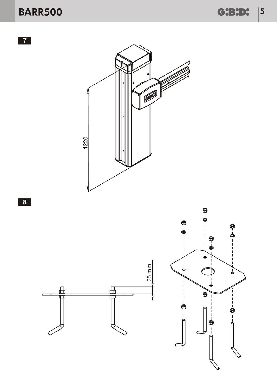
23 RR I VVRTNZ PRLIMINRI Nel campo di azione dell'operatore non devono essere presenti ostacoli di qualsiasi genere. La posa del plinto di fondazione deve avvenire in una zona di terreno libera da cavi e tubature e di caratteristiche tali da garantire una adeguata tenuta del plinto. Verificare l'esistenza di una efficiente presa di terra per il collegamento del montante. seguire l'installazione sufficientemente lontano dalla strada in modo da non costituire pericolo per la circolazione. L'ingresso ad asta motorizzata è principalmente dedicato al passaggio veicoli, se possibile eseguire un ingresso separato per i pedoni. ' buona norma segnalare l'ingresso automatizzato con targhe di avvertenza di facile visibilità ( dentro e fuori) e se il caso, che avvertano i pedoni del divieto di passaggio. In caso di incertezze sulla sicurezza dell'installazione, sospendere il lavoro e contattare il rivenditore. ontrollare la presenza di cavi aerei di media ed alta tensione e rispettare la distanza minima di isolamento in aria. MURTUR PISTR I FONZION ssicurarsi di posizionare la piastra di fondazione in modo tale da garantire la corretta operatività dell'operatore e un facile accesso per le successive fasi di installazione o future manutenzioni. 1 - ssemblare la piastra di fondazione (8). 2 - seguire un plinto di fondazione (9) comprensivo di uno o più tubi di diametro adeguato per il passaggio cavi. Verificare con la bolla il posizionamento della piastra di fondazione INSTLLZION OPRTOR 1 - Svitare le sei viti laterali per togliere il cofano frontale (10). 2 - Posizionare l'operatore sulla piastra di fondazione e fissarlo con i quattro dadi e rondelle presenti sulla piastra di fondazione (11). efinire se l'installazione è STR o SINISTR (12). 3 - Una volta definita l'installazione come destra o sinistra, se necessario bisogna provvedere a spostare il dispositivo di bilanciamento che accoglierà la/le molle (non fornite assieme all'operatore). In caso di installazione sinistra il dispositivo di bilanciamento è a sinistra. In caso di installazione destra il dispositivo di bilanciamento è a destra. L'operatore viene sempre fornito col dispositivo di bilanciamento fissato in posizione destra pertanto in caso di installazione destra non è necessario spostare il dispositivo di bilanciamento. Seguire la procedura onversione STRO-SINISTRO della sbarra per spostare il dispositivo di bilanciamento.
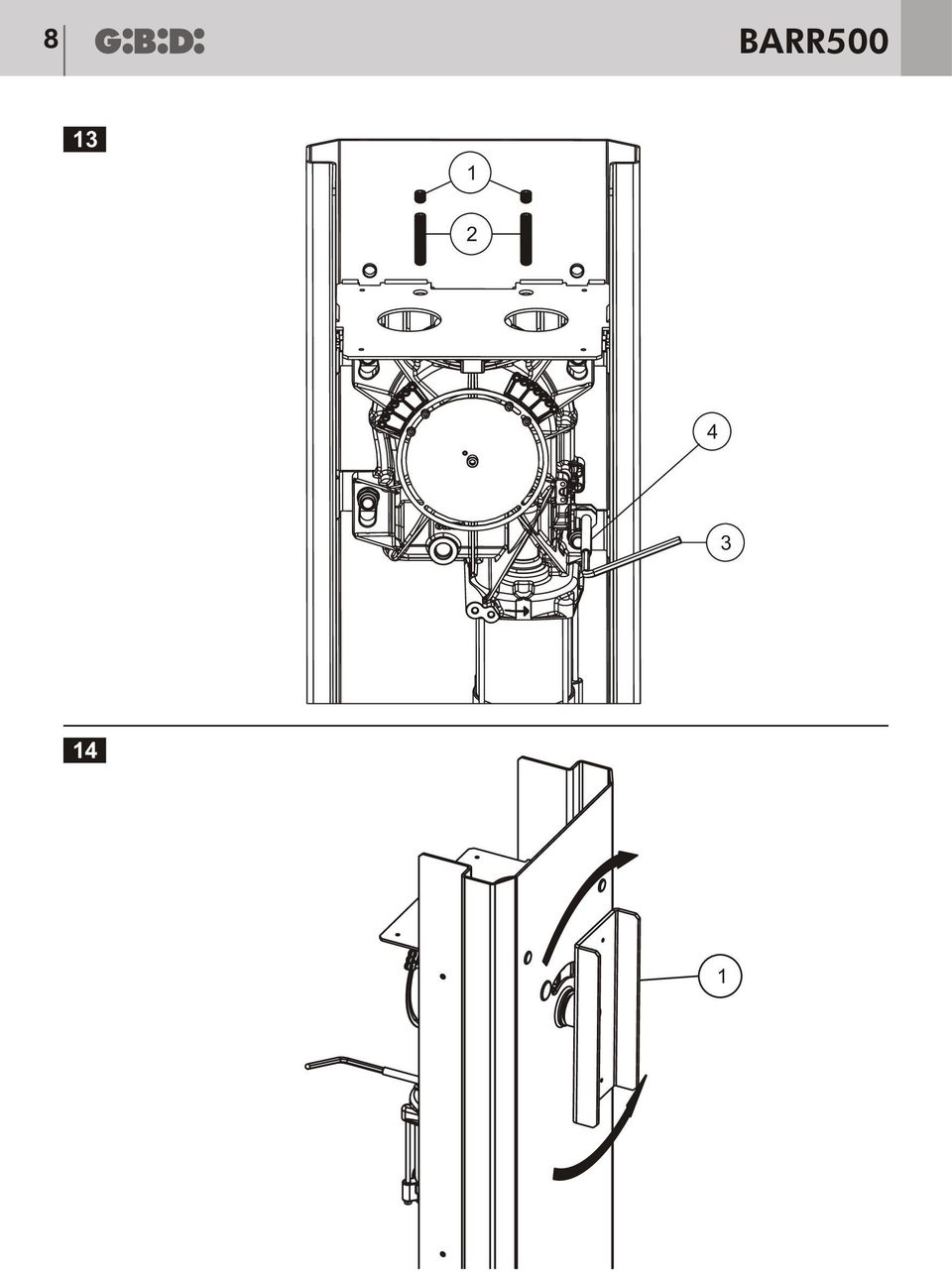
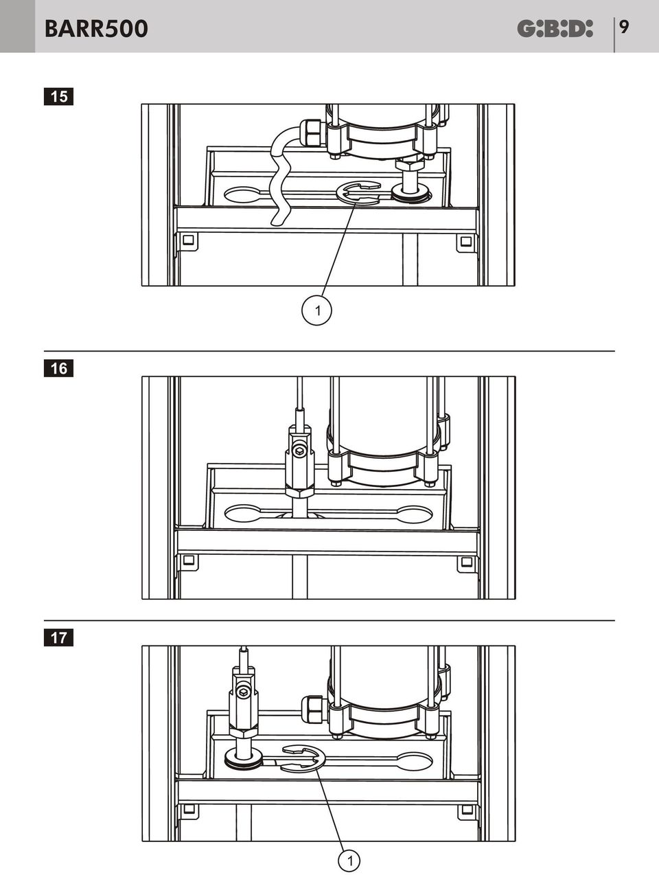
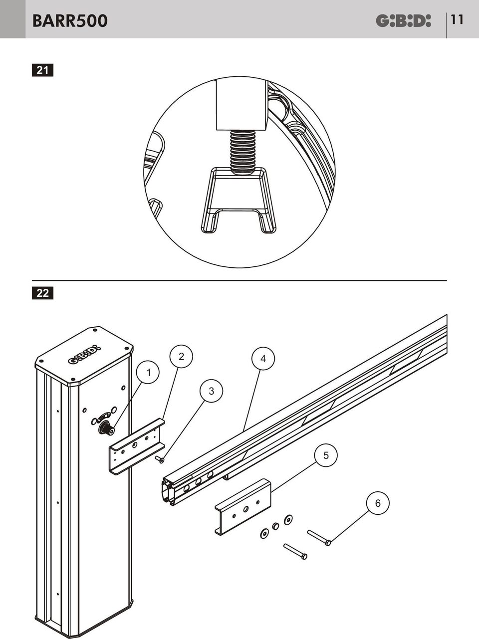
24 24 RR500 I ONVRSION STRO-SINISTRO LL SRR 1 - Svitare i due grani 1 (13) di fermo ed i due grani lunghi 2 (13) che fungono da finecorsa meccanico. 2 - Sbloccare l'operatore con la chiave 3 (13) in dotazione agendo sull'asta dello sblocco 4 (13). Se la fune del dispositivo di bilanciamento non è già visibilmente molto allentata agire manualmente sull'albero di uscita dell'operatore con l'ausilio del giunto asta 1 (14) ruotandolo nel verso opportuno per ottenere il risultato desiderato. 3 - on l'ausilio di un cacciavite estrarre l'anello seeger radiale 1 (15) che ferma la bussola del dispositivo di bilanciamento. 4 - Fare scorrere lo stelo del dispositivo di bilanciamento nella apposita fessura presente sulla piastra fino al raggiungimento della nuova sede (16). 5 - Reinserire l'anello seeger radiale 1 (17) per fissare nuovamente la bussola del dispositivo di bilanciamento. Ruotare l'albero di uscita dell'operatore con l'ausilio del giunto 1 (14) per allineare la fune con lo stelo. 6 - on l'ausilio di un cacciavite a taglio piccolo estrarre i tappi di plastica 1 (18) che coprono i fori grandi nella parte posteriore del montante 7 - on i fori liberi dai tappi è possibile vedere l'accoppiamento fra il grano di finecorsa 2 (13) e la battuta meccanica presente sull'operatore (19). La battuta meccanica di finecorsa in apertura è sempre visibile dal foro 2 (20) opposto alla molla, la battuta meccanica di finecorsa in chiusura è sempre visibile dal foro 1 (20) sul lato dove è la molla. 8 - Ruotare l'albero di uscita dell'operatore con l'ausilio del giunto 1 (14) fin tanto che non vengono individuate le battute di finecorsa in apertura e chiusura e avvitare i due grani lunghi fino a che l'estremità di questi non tocchi la battuta meccanica (21). INSTLLZION I GIUNTI SUPPORTO ST 1 - ssicurarsi di avere i giunti giusti per il tipo di asta utilizzata. 2 - Sbloccare l'operatore se già non lo fosse (vedi capitolo MNOVR MNUL ). 3 - Innestare anche non completamente il giunto 2 (22) sull'albero scanalato 1 (22) in qualsiasi posizione, in questa fase non è necessario alcun allineamento. 4 - Ruotare in giunto 2 (22) nel senso di chiusura della sbarra fino al raggiungimento del finecorsa meccanico. 5 - strarre il giunto 2 (22) improntato precedentemente. questo punto è possibile montare l'asta in due modi: 6 - Inserire il giunto 2 (22) sull'albero scanalato 1 (22) in posizione orizzontale ed avvitare la vite 3 (22) a testa svasata. 7- Inserire l'asta 4 (22) sul giunto 2 (22), la copertura del giunto 5 (22) ed avvitare il tutto con le viti 6 (22). Oppure 6 - omporre a parte l'asta col giunto 2 (22), la copertura del giunto 5 (22) e chiudere il tutto con la viteria in dotazione 6 (22). 7 - Inserire il gruppo giunto con asta appena creato sull'albero scanalato 1 (22) e fissare il tutto con la vite a testa svasata 3 (22). Nota: Si raccomanda il buon serraggio della vite a testa svasata 3 (22).
25 RR I INSTLLZION LL MOLL Le barriere RR524 e RR526 vengono fornite senza molle che vanno scelte in base alla lunghezza dell'asta ed in base agli accessori montati sull'asta stessa. Una volta scelte le molle giuste per la specifica installazione seguire queste semplici istruzioni: 1- Sbloccare l'operatore(vedi capitolo MNOVR MNUL) 2- Portare manualmente l'asta in posizione verticale. 3- loccare l'operatore. 4 - on una chiave esagonale svitare la vite 1 (23) che fissa il dispositivo di bilanciamento alla fune e con un cacciavite a taglio sfilare l'anello seeger radiale 2 (23) dalla bussola. 5 - strarre il dispositivo di bilanciamento 3 (23) dal proprio alloggiamento e comporlo con le molle a disposizione. 6 - sistono due tipologie di kit molle, quello a singola molla e quello con doppia molla. Il tubo guida-molla 1 (24) è sempre presente, va sempre utilizzato e va infilato per primo sullo stelo 6 (24) del dispositivo di bilanciamento, a seguire bisogna infilare la molla o le molle 2 e 3 (24). Nel caso della doppia molla infilare prima quella piccola 2 (24). 7 - Ricomporre il dispositivo di bilanciamento avvitando il dado 4 (24) sullo stelo 6 (24) per l'altezza del dado. 8 - Lubrificare la/le molle con grasso adesivo spray. 9 - Reinserire il dispositivo di bilanciamento nel suo alloggiamento tramite la vite 1 (24) e l anello seeger radiale 2 (24) vvitare il dado 4 (24) ed avvitare il controdado 5 (24) sullo stelo 6 (24). RGOLZION L ISPOSITIVO I ILNIMNTO 1 - ssicurarsi che la molla montata sia adatta all'asta adottata nella specifica installazione (tabella 25b) 2 - Sbloccare l'operatore. 3 - Portare l'asta a 45 e lasciarla delicatamente. 4 - Se l'asta tende a salire o scendere è necessario regolare il carico della molla. 5 - Portare manualmente l'asta in posizione verticale. 6 - loccare l'operatore. 7 - Svitare il controdado 3 (25). 8 - vvitare il dado 1 (25) tenendo ferma con una chiave la forcella esagonale 2 (25). 9 - Sbloccare l'operatore Portare l'asta a 45 e lasciarla delicatamente Se l'asta rimane ferma procedere al punto 12 altrimenti ripetere il punto vvitare il controdado 3 (25).
26 26 RR500 I 25b OPTIONL PR PROFILO ST 100x66 mm Lunghezza asta (m) sta sta + Luce sta + osta sta + osta + Luce sta + Piedino sta + Piedino + Luce sta + Piedino + osta sta + Piedino + osta + Luce sta + Siepe sta + Siepe + Luce sta + Siepe + Piedino sta + Siepe + Piedino + Luce sta Spezzata sta Spezzata + Luce sta Spezzata + osta sta Spezzata + osta + Luce sta Spezzata + Piedino sta Spezzata + Piedino + Luce sta Spezzata + Piedino + osta + Luce 2 2,5 3 3,5 4 4,5 5 5,5 6 OPTIONL PR PROFILO ST 80x40 mm Lunghezza asta (m) sta sta + osta sta + Piedino sta + osta + Piedino sta + Siepe sta + Siepe + Piedino 2 2,5 3 3,5 4 4,5 5 5,5 6 LGN MOLL M13330 M1019G M13320 M13320+M13330 M13320+M1019G 1400 N 3100 N 4300N 5700 N 7400 N
27 RR I RGOLZION FINORS MNII I Finecorsa meccanici possono essere regolati agendo su due grani accessibili dai fori 1 e 2 (26) presenti sulla piastra di supporto del contenitore apparecchiatura. Per accedere ai due grani lunghi di regolazione bisogna svitare completamente i due grani corti che hanno la funzione di bloccare i grani lunghi. Prendendo come riferimento figura 26, il grano 1 funge da finecorsa meccanico in chiusura mentre il grano 2 funge da finecorsa in apertura. vvitando il grano 1 si anticipa il momento in cui questo incontrerà la battuta meccanica dell'operatore in fase di chiusura arrestandone il moto ( la barriera chiuderà di meno). Svitando il grano 1 si ritarda il momento in cui questo incontra la battuta meccanica dell'operatore in fase di chiusura arrestandone il moto (la barriera chiuderà di più). vvitando il grano 2 si anticipa il momento in cui questo incontrerà la battuta meccanica dell'operatore in fase di apertura arrestandone il moto ( la barriera aprirà di meno). Svitando il grano 2 si ritarda il momento in cui questo incontra la battuta meccanica dell'operatore in fase di apertura arrestandone il moto ( la barriera aprirà di più). ' buona norma procedere con regolazioni dell'ordine di 1-2 giri di avvitamento-svitamento per evitare effetti indesiderati ed eccessivi. Si consiglia l'utilizzo di LOTIT 243 ( frenafiletti leggero) per garantire la stabilità dei grani lunghi di finecorsa. Ricordarsi di reinserire i grani corti. ' necessario che la battuta dei finecorsa meccanici avvenga successivamente alla fine del moto regolato dai finecorsa elettrici ( obbligatori ) pertanto è necessario predisporre i finecorsa meccanici leggermente oltre al punto di fine moto effettivamente desiderato. INSTLLZION PPRHITUR ssicurarsi che tensione e frequenza di alimentazione siano compatibili con l'apparecchiatura. Non stagnare le estremità dei cavi che vanno inseriti nelle morsettiere dell'apparecchiatura. L'apparecchiatura è posizionata all'interno di un contenitore plastico 1 (27) che si fissa sul montante dell'operatore con quattro viti 2 (27). Per il passaggio dei cavi è necessario creare almeno un foro in una delle quattro zone perforabili 3 (27). Si consiglia l'utilizza di passacavi adeguati. Il contenitore apparecchiatura va richiuso col coperchio 4 (27) usando le viti 5 (27). Rifarsi al manuale della centrale per i collegamenti elettrici, l'uso e la programmazione. Figura 28 mostra i cavi che escono dall'operatore.
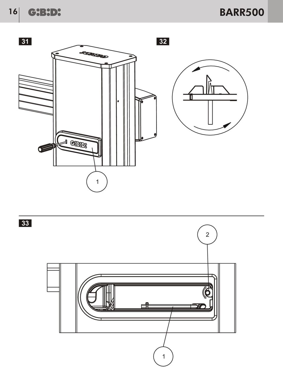
28 28 RR500 I RGOLZION FINORS LTTRII La regolazione dei finecorsa elettrici va sempre effettuata ad operatore scollegato dalla rete elettrica. Rimuovendo il cofano frontale è possibile accedere al gruppo dei finecorsa elettrici che è costituito da: Un disco in acciaio inox fisso da non muovere 1(29). ue supporti magneti in plastica nera 2 (29) che è possibile muovere allentando le viti 3 (29). Su un supporto andranno montati i due magneti che gestiscono il movimento di apre e sull'altro supporto andranno montati i due magneti che gestiscono il movimento di chiude. Quattro magneti, due per gestire il movimento di apre e due per gestire il movimento di chiude. I magneti sono premontati sui supporti. I magneti agiscono sul sensore ad effetto hall premontato sull'operatore 4 (29). Su ogni singolo supporto 2 (29) sono premontati due magneti orientati nello stesso senso di polarizzazione; per distinguere il senso di polarizzazione il magnete che controlla la chiusura ha la faccia in vista colorata di rosso, si avrà pertanto un supporto 2 (29) con due magneti non colorati ed un supporto 2 (29) con due magneti colorati. Utilizzando centrali Gi.i.i. opportunamente predisposte,il primo magnete che passa sul sensore ad effetto hall determina l'inizio del moto in rallentamento ed il secondo magnete determina la fine del moto in rallentamento (30). Rifarsi alle istruzioni della centrale di comando. Sul supporto magnete sono presenti vari fori di alloggiamento del magnete, la distanza fra un foro e l'altro equivale a 5 del movimento dell'asta, è possibile ottenere un angolo di rallentamento massimo di 25 sia in apertura che in chiusura (30). MNOVR MNUL (SLOO) Prima, durante e fino al successivo blocco è necessario togliere alimentazione all'impianto. 1 - seguire la manovra in assenza di alimentazione. 2 - ccedere alla chiave esagonale in dotazione rimuovendo lo sportellino 1 (31). Per rimuovere lo sportellino utilizzare un cacciavite di dimensioni adeguate, infilarlo nella fessura dello sportellino ed inclinarlo verso destra fino a sganciare la linguetta di fermo (32). 3 - Rimuovere lo sportellino, prelevare la chiave esagonale 1 (33) dal proprio alloggiamento ed utilizzarla per ruotare l'asta di sblocco 2 (33). La direzione di rotazione non ha importanza, compiuti circa 180 si sente uno scatto che indica che l'operatore è sbloccato. L'operatore rimane sbloccato fino a che non si agisce nuovamente con la chiave esagonale. TTNZION: quando si attiva lo sblocco l'asta può alzarsi da sola fino a 45. Ora è possibile muovere l'asta. Per ribloccare l'operatore è sufficiente ruotare ulteriormente la chiave di sblocco.
29 RR I ISINSTLLZION I GIUNTI SUPPORTO ST Se è presente la molla e si pensa che in seguito alla rimozione dei giunti asta sia necessario sbloccare l'operatore provvedere a seguire prima la procedura Sgancio del dispositivo di bilanciamento 1 - L'asta deve essere in posizione orizzontale. 2 - Svitare le viti a testa esagonale 6 (22) che chiudono il giunto. 3 - strarre la copertura del giunto 5 (22) e l'asta 4 (22). 4 - llentare la vite a testa svasata 3 (22). 5 - Utilizzare un estrattore di dimensioni adeguate per sfilare il giunto dall'albero scanalato utilizzando come punto di perno la testa della vite svasata 3 (22). ' vivamente sconsigliato cercare di sfilare il giunto con metodi alternativi. TTNZION: Se è presente la molla, col giunto in posizione orizzontale questa è compressa pertanto non eseguire la manovra di sblocco senza asta montata. SGNIO L ISPOSITIVO I ILNIMNTO 1 - Sbloccare l'operatore(vedi capitolo MNOVR MNUL). 2 - portare manualmente l'asta in posizione verticale. 3 - loccare l'operatore. 4 - liminare il precarico della molla agendo sul dado 1(25) tenendo ferma con una chiave la forcella esagonale 2 (25). 5 - on una chiave esagonale svitare la vite 1 (23) che fissa il dispositivo di bilanciamento alla fune. SSORI ISPONIILI lcuni accessori comportano un incremento della massa complessiva dell'asta influendo sulla scelta della/delle molle da usare. SUPPORTO FORLL (34) Il supporto a forcella è particolarmente utile in caso di aste lunghe oltre i 3 m perché evita che forze esterne possano piegare l'asta. PIINO (35) La funzione del piedino è similare a quella dell'appoggio col vantaggio di sollevarsi assieme all'asta e di non essere più di ingombro ad asta verticale. Si consiglia l'uso del piedino per aste non oltre i 4 m. RSTRLLIR (36) La rastrelliera è un' optional utile ad aumentare la visibilità dell'asta che chiude il varco. KIT ST SPZZT (37) L'asta spezzata è utile nella gestione dei varchi con limitate possibilità di ingombro verticale.
30 30 RR500 I LUI ST (38) Sul profilo standard dell'asta è possibile montare due tubi luminosi per aumentare la visibilità dell'asta. La figura 38 mostra la modalità corretta per l'installazione del tubo luminoso, il cavo di alimentazione (1) passa nella parte cava interna dell'asta, all'interno dell'asta questo si congiunge con il tubo luminoso (3) il quale trova poi alloggiamento nelle sedi appositamente ricavate sul profilo fino a terminare dallo stesso lato del cavo di alimentazione (2). Si raccomanda di usare giunzioni e terminali specifici per il tubo utilizzato. ORO SNSIIL Il profilo standard dell'asta consente l'inserimento di un bordo sensibile di tipo 8K2 senza il bisogno di ulteriori supporti. LMPGGINT (39) Sistema di segnalazione integrato col mobile della barriera. SLOO ON HIV UROP (40) onsente l'accesso al sistema di sblocco tramite l'utilizzo di una chiave con cilindro europeo. OPRTUR GIUNTI ST OPRTUR FIN ST (41) Sono particolarmente utili nella gestione delle cablature degli accessori per asta (luci e bordo sensibile) e di gradevole aspetto. MNUTNZION La manutenzione deve essere a cura dell'installatore e/o di personale qualificato. Ogni 6 mesi o 100,000 manovre è consigliabile eseguire un controllo del sistema : ontrollo visivo dell'operatore ed eventuale pulizia. Verifica del corretto allineamento dell'asta. Verifica del corretto funzionamento dei finecorsa elettrici e meccanici. Verifica dell'efficienza del sistema di sblocco. Verifica della corretta regolazione della/delle molle. Lubrificare con grasso adesivo spray la/le molle. Verifica del corretto fissaggio del giunto asta sull'albero scanalato di uscita. Verifica dello stato di usura della bussola di plastica auto lubrificante del dispositivo di bilanciamento. Verifica delle condizioni del cavo di trazione. Verificare il fissaggio del motoriduttore al mobile. Verificare l'integrità dei cavi di collegamento Verificare l'efficienza delle batterie se presenti. MLFUNZIONMNTO Per qualsiasi anomalia di funzionamento, togliere I'alimentazione al sistema e chiedere I'intervento di personale qualificato (installatore).
31 RR I ichiarazione di conformità Il fabbricante: GI.I.I. S.r.l. Via betone rennero, 177/, Poggio Rusco (MN) ITLY ichiara che i prodotti: RRIR LTTROMNIH RR Sono conformi alle seguenti irettive : irettiva M 2004/108/ e successive modifiche; e che sono state applicate le seguenti norme armonizzate: N , N ata 15/02/2010 Firma mministratore elegato Oliviero rosio
32 32 RR500 I MNUTNZION STRORINRI ata: Timbro ditta installatrice: Firma tecnico: ata nnotazioni Firma Tecnico ata: Timbro ditta installatrice: Firma tecnico: ata nnotazioni Firma Tecnico
33 RR UK INTROUTION The new 24 V automatic electromechanical barrier for easy system control with booms of up to 6 metres and highspeed opening. With a contemporary design and new technological solutions, RR500 is the right answer to all these requirements. esigned for easy adaptation to the N standards. efore proceeding with installation, fit a magnetothermal/differential switch with a maximum capacity of 10 upstream of the system. The switch must guarantee omnipolar separation of the contacts with an opening INSTLLTION WRNINGS distance of at least 3mm. Keep all the materials contained in the packaging away from children since they pose a potential risk. The manufacturer declines all responsibility for improper functioning of the automated device if the original components and accessories suitable for the specific application are not used. fter installation, always carefully check proper functioning of the system and the devices used. This instruction manual addresses professionals qualified to install live equipment and therefore requires good technical knowledge and installation in compliance with the regulations in force. Maintenance must be carried out by qualified personnel. efore carrying out any cleaning or maintenance operation, disconnect the control unit from the mains. This product has been designed and constructed exclusively for the use indicated in this documentation. ny other use may cause damage to the product and be a source of danger. Verify the end purpose of the product and take all the necessary safety precautions. Use of the products for purposes different from the intended use has not been tested by the manufacturer and is therefore on full responsibility of the installer. Mark the automated device with visible warning plates. Warn the user that children or animals should not play or stand near the gate. ppropriately protect the dangerous points (for example, using a sensitive frame). heck proper installation of the earthing system. connect all the metal parts of doors, gates, etc. and all the system components to an earth terminal. xclusively use original spare parts for any maintenance or repair operations. o not modify any components of the automated device unless expressly authorised by Gi.i.i. se suitable cable clamps to ensure that the wiring is properly connected mechanically and such that an IP44 U degree of protection is maintained. WRNING: IMPORTNT SFTY INSTRUTIONS. It is important to follow these instructions in order to safeguard people. Incorrect installation or improper use of the product may lead to serious harm to people. Keep this instruction booklet and read it carefully before starting installation.
34 34 RR500 UK WRNINGS FOR TH USR In the event of an operating fault or failure, cut the power upstream of the control unit and call Technical Service. Periodically check good functioning of the safety devices. ny repairs must be carried out by specialised personnel using original and certified materials. The product may not be used by children or persons with reduced physical, sensorial or mental capacities or without experience and knowledge. o not access the board for adjustments and/or maintenance. LTRIL STUP lectric system setup Set up the electric system as shown in Fig. 1 referring to the electric system regulations and other national regulations in force. Keep the mains power connections clearly separated from the service connections (photocells, sensitive frames, control devices, etc.). The main components of the automated device are: 1-24V flashing light; 0.75 mm² 2-core (2x0.75) cable 2 - ntenna; screened coaxial cable 3 - Key selector; 0.5 mm² 3-core (3x0.5) cable 4 - Photocell receiver; 0.5 mm² 4-core (4x0.5) cable 5 - Photocell transmitter; 0.5 mm² 2-core (2x0.5) cable 6 - Omnipolar magnetothermal/differential switch with minimum contact opening of 3 mm V/50-60 Hz power line to the device; 1.5 mm² 3-core cable (3x1.5) (adhere to the regulations in force) 7 - lectronic control unit container; 3x1.5 mm² cable 8-24V operator: mm² 2-core (2x1.5) power cable R = + LK = - for a maximum cable length of 6 m, beyond which the cable cross-section needs to be increased 9-8K2 sensitive edge; 0.5 mm² 2-core (2x0.5) cable V boom light; min. 1.5 mm² 2-core (2x1.5) cable Use appropriate cable ducts. It is good practice to separate the 230V power cables from the accessory connection cables and it is therefore advisable to use at least two tubes to run the cables through. WRNING: It is important to fit an omnipolar magnetothermal/differential switch with a minimum contact opening of 3 mm on the power line upstream of the control unit.
Door Hinge replacement (Rear Left Door)
") Door Hinge replacement (Rear Left Door) We will continue the previous article by replacing the hinges of the rear left hand side door. I will use again the same procedure and means I employed during the
Door Hinge replacement (Rear Left Door) We will continue the previous article by replacing the hinges of the rear left hand side door. I will use again the same procedure and means I employed during the
MOTORI PER VENTILATORI MOTORS FOR BLOWERS
 MOTORI PER VENTILATORI MOTORS FOR BLOWERS LR 91167 FLANGIA TIPO A FLANGE TYPE A TIPO / TYPE A B C D E F G H I* L M N O P Q BM.80.A2.1000 315 250 290 20 225 φ 7 155 33 19 h7 114 84 6 21.5 M 8 3/8 BM.80.A2.1001
the total number of electrons passing through the lamp.
 1. A 12 V 36 W lamp is lit to normal brightness using a 12 V car battery of negligible internal resistance. The lamp is switched on for one hour (3600 s). For the time of 1 hour, calculate (i) the energy
ΟΔΗΓΙΕΣ ΕΓΚΑΤΑΣTΑΣΗΣ ΓΙΑ ΠΑΤΩΜΑ WPC INSTALLATION GUIDE FOR WPC DECKING
 1/12 ΟΔΗΓΙΕΣ ΕΓΚΑΤΑΣTΑΣΗΣ ΓΙΑ ΠΑΤΩΜΑ WPC INSTALLATION GUIDE FOR WPC DECKING Ανοίγουμε τρύπες Ø8 x 80mm στο σημείο κατασκευής, με τρυπάνι. To προτεινόμενο πλάτος και μήκος μεταξύ των 2 οπών να είναι 30-35εκ.,
ΠΟΡΤΕΣ ΑΝΑΚΑΙΝΙΣΗΣ DOORS FOR MODERNIZATION
 ΠΟΡΤΕΣ ΑΝΑΚΑΙΝΙΣΗΣ DOORS FOR MODERNIZATION ΠΟΡΤΑ ΟΡΟΦΟΥ ΚΕΝΤΡΙΚΗ 2ΦΥΛΛΗ 2 PANELS CENTRE PARTING LANDING DOOR.1. Πόρτα ορόφου χωρίς κάσωμα, για ανακαινίσεις Landing door without frames, for modernization
UDZ Swirl diffuser. Product facts. Quick-selection. Swirl diffuser UDZ. Product code example:
 UDZ Swirl diffuser Swirl diffuser UDZ, which is intended for installation in a ventilation duct, can be used in premises with a large volume, for example factory premises, storage areas, superstores, halls,
Potential Dividers. 46 minutes. 46 marks. Page 1 of 11
 Potential Dividers 46 minutes 46 marks Page 1 of 11 Q1. In the circuit shown in the figure below, the battery, of negligible internal resistance, has an emf of 30 V. The pd across the lamp is 6.0 V and
Capacitors - Capacitance, Charge and Potential Difference
 Capacitors - Capacitance, Charge and Potential Difference Capacitors store electric charge. This ability to store electric charge is known as capacitance. A simple capacitor consists of 2 parallel metal
Περιεχόμενα / Contents
 Aερόθερμo / Fan Heater PTC-906 Περιεχόμενα / Contents GR... Σελίδες 3-8 EN... Pages 9-11 2 GR Ευχαριστούμε που επιλέξατε μια συσκευή της γκάμας θερμαντικών IZZY. Σημαντικές Οδηγίες Ασφαλείας Τα Μέρη της
!Stato di tensione triassiale!stato di tensione piano!cerchio di Mohr
 !Stato di tensione triassiale!stato di tensione piano!cerchio di Mohr Stato di tensione F A = F / A F Traione pura stato di tensione monoassiale F M A M Traione e torsione stato di tensione piano = F /
CHAPTER 25 SOLVING EQUATIONS BY ITERATIVE METHODS
 CHAPTER 5 SOLVING EQUATIONS BY ITERATIVE METHODS EXERCISE 104 Page 8 1. Find the positive root of the equation x + 3x 5 = 0, correct to 3 significant figures, using the method of bisection. Let f(x) =
[1] P Q. Fig. 3.1
![[1] P Q. Fig. 3.1](/thumbs/79/80362156.jpg "[1] P Q. Fig. 3.1") 1 (a) Define resistance....... [1] (b) The smallest conductor within a computer processing chip can be represented as a rectangular block that is one atom high, four atoms wide and twenty atoms long. One
1 (a) Define resistance....... [1] (b) The smallest conductor within a computer processing chip can be represented as a rectangular block that is one atom high, four atoms wide and twenty atoms long. One
MSN DESK TOP ENCLOSURE WITH STAND / CARRYING HANDLE
 MSN SERIES MSN DESK TOP ENCLOSURE WITH STAND / CARRYING HANDLE W H FEATURE Available in 176 sizes. Stand / carrying handle can be adjusted in 30 degree. Maximum load is kg. There are no ventilation hole
MS SERIES MS DESK TOP ENCLOSURE APPLICATION EXAMPLE FEATURE. Measuring instruments. Power supply equipments
 MS SERIES MS DESK TOP ENCLOSURE FEATURE Available in 176 sizes. Screws are not appeared on the surface. Usable as rack mount case with optinal mounting bracket. There are no ventilation hole for cover
HOMEWORK 4 = G. In order to plot the stress versus the stretch we define a normalized stretch:
 HOMEWORK 4 Problem a For the fast loading case, we want to derive the relationship between P zz and λ z. We know that the nominal stress is expressed as: P zz = ψ λ z where λ z = λ λ z. Therefore, applying
OUR PRODUCT RANGE. www.rakson.gr
 ΤΑ ΑΛΛΑ ΕΙ Η ΠΡΟΪΟΝΤΑ ΜΑΣ ΜΕΤΑΣΧΗΜΑΤΙΣΤΕΣ ΚΟΥ ΟΥΝΙΩΝ ΚΟΥ ΟΥΝΙΑ ΜΠΟΥΤΟΝ ΚΟΥ ΟΥΝΙΩΝ ΑΥΤΟΜΑΤΟΙ ΚΛΙΜΑΚΟΣΤΑΣΙΟΥ ΚΛΕΙ ΑΡΙΕΣ ΑΝΙΧΝΕΥΤΕΣ ΚΙΝΗΣΗΣ ΣΥΣΤΗΜΑΤΑ ΕΠΙΚΟΙΝΩΝΙΑΣ Θυροτηλεοράσεις Θυροτηλέφωνα Ενδοεπικοινωνίες
2 Composition. Invertible Mappings
 Arkansas Tech University MATH 4033: Elementary Modern Algebra Dr. Marcel B. Finan Composition. Invertible Mappings In this section we discuss two procedures for creating new mappings from old ones, namely,
ΚΥΠΡΙΑΚΗ ΕΤΑΙΡΕΙΑ ΠΛΗΡΟΦΟΡΙΚΗΣ CYPRUS COMPUTER SOCIETY ΠΑΓΚΥΠΡΙΟΣ ΜΑΘΗΤΙΚΟΣ ΔΙΑΓΩΝΙΣΜΟΣ ΠΛΗΡΟΦΟΡΙΚΗΣ 19/5/2007
 Οδηγίες: Να απαντηθούν όλες οι ερωτήσεις. Αν κάπου κάνετε κάποιες υποθέσεις να αναφερθούν στη σχετική ερώτηση. Όλα τα αρχεία που αναφέρονται στα προβλήματα βρίσκονται στον ίδιο φάκελο με το εκτελέσιμο
Operating Instructions and Parts Manual 14-inch Woodworking Band Saw Models JWBS-14SF and JWBS-14SF-3
 Operating Instructions and Parts Manual 14-inch Woodworking Band Saw Models JWBS-14SF and JWBS-14SF-3 Model #714500 shown JET 427 New Sanford Road LaVergne, Tennessee 37086 Part No. M-714500 Ph.: 800-274-6848
EE512: Error Control Coding
 EE512: Error Control Coding Solution for Assignment on Finite Fields February 16, 2007 1. (a) Addition and Multiplication tables for GF (5) and GF (7) are shown in Tables 1 and 2. + 0 1 2 3 4 0 0 1 2 3
Advanced Subsidiary Unit 1: Understanding and Written Response
 Write your name here Surname Other names Edexcel GE entre Number andidate Number Greek dvanced Subsidiary Unit 1: Understanding and Written Response Thursday 16 May 2013 Morning Time: 2 hours 45 minutes
Gruppo idraulico solare a singola via
 Gruppo idraulico a singola via per impianti solari termici ΣΥΓΚΡΟΤΗΜΑ ΚΥΚΛΟΦΟΡΗΤΗ ΜΟΝΗΣ ΓΡΑΜΜΗΣ ΓΙΑ ΗΛΙΑΚΑ ΣΥΣΤΗΜΑΤΑ ΒΕΒΙΑΣΜΕΝΗΣ ΚΥΚΛΟΦΟΡΙΑΣ Il Descrizione Περιγραφή gruppo di circolazione viene utilizzato
9.09. # 1. Area inside the oval limaçon r = cos θ. To graph, start with θ = 0 so r = 6. Compute dr
 9.9 #. Area inside the oval limaçon r = + cos. To graph, start with = so r =. Compute d = sin. Interesting points are where d vanishes, or at =,,, etc. For these values of we compute r:,,, and the values
Right Rear Door. Let's now finish the door hinge saga with the right rear door
 Right Rear Door Let's now finish the door hinge saga with the right rear door You may have been already guessed my steps, so there is not much to describe in detail. Old upper one file:///c /Documents
Εγκατάσταση λογισμικού και αναβάθμιση συσκευής Device software installation and software upgrade
 Για να ελέγξετε το λογισμικό που έχει τώρα η συσκευή κάντε κλικ Menu > Options > Device > About Device Versions. Στο πιο κάτω παράδειγμα η συσκευή έχει έκδοση λογισμικού 6.0.0.546 με πλατφόρμα 6.6.0.207.
Operating Instructions and Parts Manual 14-inch Woodworking Band Saw Models JWBS-14SF and JWBS-14SF-3
 Operating Instructions and Parts Manual 14-inch Woodworking Band Saw Models JWBS-14SF and JWBS-14SF-3 Model #714500 shown JET 427 New Sanford Road LaVergne, Tennessee 37086 Part No. M-714500 Ph.: 800-274-6848
ANSWERSHEET (TOPIC = DIFFERENTIAL CALCULUS) COLLECTION #2. h 0 h h 0 h h 0 ( ) g k = g 0 + g 1 + g g 2009 =?
 COLLECTION #2. h 0 h h 0 h h 0 ( ) g k = g 0 + g 1 + g g 2009 =?") Teko Classes IITJEE/AIEEE Maths by SUHAAG SIR, Bhopal, Ph (0755) 3 00 000 www.tekoclasses.com ANSWERSHEET (TOPIC DIFFERENTIAL CALCULUS) COLLECTION # Question Type A.Single Correct Type Q. (A) Sol least
Teko Classes IITJEE/AIEEE Maths by SUHAAG SIR, Bhopal, Ph (0755) 3 00 000 www.tekoclasses.com ANSWERSHEET (TOPIC DIFFERENTIAL CALCULUS) COLLECTION # Question Type A.Single Correct Type Q. (A) Sol least
ΚΥΠΡΙΑΚΗ ΕΤΑΙΡΕΙΑ ΠΛΗΡΟΦΟΡΙΚΗΣ CYPRUS COMPUTER SOCIETY ΠΑΓΚΥΠΡΙΟΣ ΜΑΘΗΤΙΚΟΣ ΔΙΑΓΩΝΙΣΜΟΣ ΠΛΗΡΟΦΟΡΙΚΗΣ 6/5/2006
 Οδηγίες: Να απαντηθούν όλες οι ερωτήσεις. Ολοι οι αριθμοί που αναφέρονται σε όλα τα ερωτήματα είναι μικρότεροι το 1000 εκτός αν ορίζεται διαφορετικά στη διατύπωση του προβλήματος. Διάρκεια: 3,5 ώρες Καλή
Οδηγίες Λειτουργίας. Assembly Operating instructions. Montageanleitung. Απογυμνωτές PV-AZM...3. Stripping pliers PV-AZM...3.
 MA000 MA267 (de_en) (gr_en) Montageanleitung Οδηγίες Λειτουργίας Απογυμνωτής PV-AZM... για MC3, MC4 MA000 MA267 (de_en) (gr_en) Assembly Operating instructions Stripping pliers PV-AZM... for MC3 and MC4
Tipologie installative - Installation types Type d installation - Installationstypen Tipos de instalación - Τυπολογίες εγκατάστασης
 AMPADE MOOCROMATICHE VIMAR DIMMERABII A 0 V~ - VIMAR 0 V~ DIMMABE MOOCHROME AMP AMPE MOOCHROME VIMAR VARIATEUR 0 V~ - DIMMERFÄHIGE MOOCHROMATICHE AMPE VO VIMAR MIT 0 V~ ÁMPARA MOOCROMÁTICA VIMAR REGUABE
Math 6 SL Probability Distributions Practice Test Mark Scheme
 Math 6 SL Probability Distributions Practice Test Mark Scheme. (a) Note: Award A for vertical line to right of mean, A for shading to right of their vertical line. AA N (b) evidence of recognizing symmetry
Instruction Execution Times
 1 C Execution Times InThisAppendix... Introduction DL330 Execution Times DL330P Execution Times DL340 Execution Times C-2 Execution Times Introduction Data Registers This appendix contains several tables
ΟΔΗΓΙΕΣ ΣΥΝΑΡΜΟΛΟΓΗΣΗΣ/ ASSEMBLY INSTRUCTION ΤΟΜΜΥ ΚΡΕΒΑΤΙ/BED
 ΟΔΗΓΙΕΣ ΣΥΝΑΡΜΟΛΟΓΗΣΗΣ/ ASSEMBLY INSTRUCTION ΤΟΜΜΥ ΚΡΕΒΑΤΙ/BED 1. Παρακαλώ πολύ διαβάστε προσεκτικά τις οδηγίες πριν την συναρμολόγηση/ Please read the instructions carefully. 2. Παρακαλώ πολύ όπως ελέγξτε
Έλεγχος και Διασφάλιση Ποιότητας
 Έλεγχος και Διασφάλιση Ποιότητας Ενότητα 6: Κουππάρης Μιχαήλ Τμήμα Χημείας Εργαστήριο Αναλυτικής Χημείας General Successfully carry out the Preventive Maintenance Procedure and complete the Maintenance
Code Breaker. TEACHER s NOTES
 TEACHER s NOTES Time: 50 minutes Learning Outcomes: To relate the genetic code to the assembly of proteins To summarize factors that lead to different types of mutations To distinguish among positive,
Homework 8 Model Solution Section
 MATH 004 Homework Solution Homework 8 Model Solution Section 14.5 14.6. 14.5. Use the Chain Rule to find dz where z cosx + 4y), x 5t 4, y 1 t. dz dx + dy y sinx + 4y)0t + 4) sinx + 4y) 1t ) 0t + 4t ) sinx
Ge m i n i. il nuovo operatore compatto e leggero. η καινούργια και ελαφριά αυτόματη πόρτα
 Ge m i n i 6 il nuovo operatore compatto e leggero η καινούργια και ελαφριά αυτόματη πόρτα Porte Gemini 6 Operatore a movimento lineare per porte automatiche a scorrimento orizzontale. Leggero, robusto
SPECIFICATIONS... Pag. 2. WIRE SOLDER... Pag. 3. PCB SOLDER... Pag HIGH VOLTAGE PCB SOLDER... Pag. 6. RIGHT ANGLE PCB... Pag.
 DIN 41618 & 41622 INDEX DIN 41618 SPECIFICATIONS.......................................................... Pag. 2 WIRE SOLDER............................................................ Pag. 3 PCB SOLDER.............................................................
Siemens AG Rated current 1FK7 Compact synchronous motor Natural cooling. I rated 7.0 (15.4) 11.5 (25.4) (2.9) 3.3 (4.4)
 11.5 (25.4) (2.9) 3.3 (4.4)") Synchronous motors Siemens 2009 FK7 Compact motors Nural cooling Selection and ordering da Red speed Shaft height n red S P red ΔT=00 K rpm kw (P) Red power Stic torque M 0 ΔT=00 K Red torque ) M red ΔT=00
Synchronous motors Siemens 2009 FK7 Compact motors Nural cooling Selection and ordering da Red speed Shaft height n red S P red ΔT=00 K rpm kw (P) Red power Stic torque M 0 ΔT=00 K Red torque ) M red ΔT=00
(REV:01) RYOBI 48 Volt Lawn Mower Model No. RY14110 Replacement Parts List
 RYOBI 48 Volt Lawn Mower Model No. RY14110 Replacement Parts List") 9800-86 2-0-0 (REV:0) RYOBI 48 Volt Lawn Mower Model No. RY0 Replacement Parts List RYOBI RY0 48 volt lawn mower 3 38 39 44 39 36 34 36 42 38 39 3 4 37 34 3 43 2 32 0 8 9 2 4 33 8 7 6 3 6 7 22 8 20 3 30
9800-86 2-0-0 (REV:0) RYOBI 48 Volt Lawn Mower Model No. RY0 Replacement Parts List RYOBI RY0 48 volt lawn mower 3 38 39 44 39 36 34 36 42 38 39 3 4 37 34 3 43 2 32 0 8 9 2 4 33 8 7 6 3 6 7 22 8 20 3 30
(1) Describe the process by which mercury atoms become excited in a fluorescent tube (3)
 Describe the process by which mercury atoms become excited in a fluorescent tube (3)") Q1. (a) A fluorescent tube is filled with mercury vapour at low pressure. In order to emit electromagnetic radiation the mercury atoms must first be excited. (i) What is meant by an excited atom? (1) (ii)
Q1. (a) A fluorescent tube is filled with mercury vapour at low pressure. In order to emit electromagnetic radiation the mercury atoms must first be excited. (i) What is meant by an excited atom? (1) (ii)
User s Manual / Οδηγίες Χρήσης
 User s Manual / Οδηγίες Χρήσης EUROPEAN STANDARDS Your child s safety depends on you. Proper bed rail usage cannot be assured unless you follow these instructions. DO NOT USE YOUR BED RAIL UNTILL YOU READ
(REV:01) RYOBI 48 Volt Lawn Mower Model No. RY14110A Replacement Parts List
 RYOBI 48 Volt Lawn Mower Model No. RY14110A Replacement Parts List") 9000-7 9-- (REV:0) RYOBI 4 Volt Lawn Mower Model No. RY0A Replacement Parts List RYOBI RY0A 4 VOLT LAWN MOWER 3 3 39 44 39 3 34 3 42 3 39 3 4 37 34 3 43 2 0 37 2 33 32 3 9 7 22 30 4 7 3 20 9 3 2 2 27 2
9000-7 9-- (REV:0) RYOBI 4 Volt Lawn Mower Model No. RY0A Replacement Parts List RYOBI RY0A 4 VOLT LAWN MOWER 3 3 39 44 39 3 34 3 42 3 39 3 4 37 34 3 43 2 0 37 2 33 32 3 9 7 22 30 4 7 3 20 9 3 2 2 27 2
derivation of the Laplacian from rectangular to spherical coordinates
 derivation of the Laplacian from rectangular to spherical coordinates swapnizzle 03-03- :5:43 We begin by recognizing the familiar conversion from rectangular to spherical coordinates (note that φ is used
The Simply Typed Lambda Calculus
 Type Inference Instead of writing type annotations, can we use an algorithm to infer what the type annotations should be? That depends on the type system. For simple type systems the answer is yes, and
Section 8.3 Trigonometric Equations
 99 Section 8. Trigonometric Equations Objective 1: Solve Equations Involving One Trigonometric Function. In this section and the next, we will exple how to solving equations involving trigonometric functions.
3.4 SUM AND DIFFERENCE FORMULAS. NOTE: cos(α+β) cos α + cos β cos(α-β) cos α -cos β
 cos α + cos β cos(α-β) cos α -cos β") 3.4 SUM AND DIFFERENCE FORMULAS Page Theorem cos(αβ cos α cos β -sin α cos(α-β cos α cos β sin α NOTE: cos(αβ cos α cos β cos(α-β cos α -cos β Proof of cos(α-β cos α cos β sin α Let s use a unit circle
3.4 SUM AND DIFFERENCE FORMULAS Page Theorem cos(αβ cos α cos β -sin α cos(α-β cos α cos β sin α NOTE: cos(αβ cos α cos β cos(α-β cos α -cos β Proof of cos(α-β cos α cos β sin α Let s use a unit circle
DESIGN OF MACHINERY SOLUTION MANUAL h in h 4 0.
 DESIGN OF MACHINERY SOLUTION MANUAL -7-1! PROBLEM -7 Statement: Design a double-dwell cam to move a follower from to 25 6, dwell for 12, fall 25 and dwell for the remader The total cycle must take 4 sec
Linear diffuser. Dimensions. Description
 Dimensions -- + D -- Description is a rectangular linear diffuser in aluminium. is suitable for both supply and exhaust air. is equipped with air guide baffles, making it possible to use for horizontal
Modbus basic setup notes for IO-Link AL1xxx Master Block
 n Modbus has four tables/registers where data is stored along with their associated addresses. We will be using the holding registers from address 40001 to 49999 that are R/W 16 bit/word. Two tables that
aluset sliding system for doors and windows
 aluset sliding system for doors and windows ÐÉÓÔÏÐÏÉÇÔÉÊÁ - CERTIFICATES 4 aluset ÔÅ ÍÉÊÁ ÁÑÁÊÔÇÑÉÓÔÉÊÁ ÓÕÓÔÇÌÁÔÏÓ - SYSTEM TECHNICAL FEATURES aluset 5 ÔÅ ÍÉÊH ÐÅÑÉÃÑÁÖÇ - TECHNICAL DESCRIPTION TEXNIKH
38BXCS STANDARD RACK MODEL. DCS Input/Output Relay Card Series MODEL & SUFFIX CODE SELECTION 38BXCS INSTALLATION ORDERING INFORMATION RELATED PRODUCTS
 DCS Input/Output Relay Card Series STANDARD RACK MODEL 38BXCS MODEL & SUFFIX CODE SELECTION 38BXCS MODEL CONNECTOR Y1 :Yokogawa KS2 cable use Y2 :Yokogawa KS9 cable use Y6 :Yokogawa FA-M3/F3XD32-3N use
Volume of a Cuboid. Volume = length x breadth x height. V = l x b x h. The formula for the volume of a cuboid is
 Volume of a Cuboid The formula for the volume of a cuboid is Volume = length x breadth x height V = l x b x h Example Work out the volume of this cuboid 10 cm 15 cm V = l x b x h V = 15 x 6 x 10 V = 900cm³
π H-4710 ELECTRIC PALLET TRUCK LB uline.com
 -00-9-0 Steering arm DIAGRAM 0 0 7 7 0 7 9 9 0 9 PAGE OF 0 0 PH-70 -00-9-0 Steering arm parts list Control Head Assembly ---------- 0-0000-00 Steering Arm H-70STEER 0-0000-0A Gas Spring Assembly H-00 0-0000-00
Strain gauge and rosettes
 Strain gauge and rosettes Introduction A strain gauge is a device which is used to measure strain (deformation) on an object subjected to forces. Strain can be measured using various types of devices classified
Approximation of distance between locations on earth given by latitude and longitude
 Approximation of distance between locations on earth given by latitude and longitude Jan Behrens 2012-12-31 In this paper we shall provide a method to approximate distances between two points on earth
Assalamu `alaikum wr. wb.
 LUMP SUM Assalamu `alaikum wr. wb. LUMP SUM Wassalamu alaikum wr. wb. Assalamu `alaikum wr. wb. LUMP SUM Wassalamu alaikum wr. wb. LUMP SUM Lump sum lump sum lump sum. lump sum fixed price lump sum lump
RE34. Gioco angolare in uscita. Backlash output shaft. Rapporti Ratios. Weight DIMENSIONI RIDUTTORE - GEAR DIMENSION
 RE34 1 0,8 1,2 95 5000 0,2 4 6,25 8 2 1,8 2,5 91 5000
RSDW08 & RDDW08 series
 /,, MODEL SELECTION TABLE INPUT ORDER NO. INPUT VOLTAGE (RANGE) NO LOAD INPUT CURRENT FULL LOAD VOLTAGE CURRENT EFFICIENCY (Typ.) CAPACITOR LOAD (MAX.) RSDW08F-03 344mA 3.3V 2000mA 80% 2000μF RSDW08F-05
Stato di tensione triassiale Stato di tensione piano Cerchio di Mohr
 Stato di tensione triassiale Stato di tensione iano Cerchio di Mohr Stato di tensione F A = F / A F Traione ura stato di tensione monoassiale F M A M Traione e torsione stato di tensione iano = F / A =
GAUGE BLOCKS. Grade 0 Tolerance for the variation in length. Limit deviation of length. ± 0.25μm. 0.14μm ±0.80μm. ± 1.90μm. ± 0.40μm. ± 1.
 GAUGE BLOCKS Accuracy according to ISO650 Nominal length (mm) Limit deviation of length Grade 0 Tolerance for the variation in length Grade Grade Grade Grade 2 Limit deviations of Tolerance for the Limit
Areas and Lengths in Polar Coordinates
 Kiryl Tsishchanka Areas and Lengths in Polar Coordinates In this section we develop the formula for the area of a region whose boundary is given by a polar equation. We need to use the formula for the
Operating Instructions and Parts Manual Drum Sander Model PM2244
 Operating Instructions and Parts Manual Drum Sander Model PM2244 Powermatic 427 New Sanford Road LaVergne, Tennessee 37086 Part No. M-1792244 Ph.: 800-274-6848 Edition 1 08/2015 www.powermatic.com Copyright
NMBTC.COM /
 Common Common Vibration Test:... Conforms to JIS C 60068-2-6, Amplitude: 1.5mm, Frequency 10 to 55 Hz, 1 hour in each of the X, Y and Z directions. Shock Test:...Conforms to JIS C 60068-2-27, Acceleration
TIME SWITCHES AND TWILIGHT SWITCHES
 W ANALOG DIN-RAIL TIME SWITCH QUARTZ, SERIES TEMPUS ANALOG 244 W SCHRACK-INFO Analogue time switch 1 channel Daily program With power reserve (NiMH rechargeable battery) Synchronised with mains Shortest
QUICKTRONIC PROFESSIONAL QTP5
 osram.com QUICKTRONIC PROFESSIONA QTP5 ECG for T5/ 16mm, T8/ 26mm, DUUX fluorescent lamps QTP5 i.e. UMIUX T5 HO ES 01 Product Features: Up to 100.000 hours lifetime 1 amp start with optimized filament
PhysicsAndMathsTutor.com 1
 PhysicsAndMathsTutor.com 1 Q1. The magnetic flux through a coil of N turns is increased uniformly from zero to a maximum value in a time t. An emf, E, is induced across the coil. What is the maximum value
Areas and Lengths in Polar Coordinates
 Kiryl Tsishchanka Areas and Lengths in Polar Coordinates In this section we develop the formula for the area of a region whose boundary is given by a polar equation. We need to use the formula for the
0.635mm Pitch Board to Board Docking Connector. Lead-Free Compliance
 .635mm Pitch Board to Board Docking Connector Lead-Free Compliance MINIDOCK SERIES MINIDOCK SERIES Features Specifications Application.635mm Pitch Connector protected by Diecasted Zinc Alloy Metal Shell
SPEEDO AQUABEAT. Specially Designed for Aquatic Athletes and Active People
 SPEEDO AQUABEAT TM Specially Designed for Aquatic Athletes and Active People 1 2 Decrease Volume Increase Volume Reset EarphonesUSBJack Power Off / Rewind Power On / Fast Forward Goggle clip LED Status
Quick Installation Guide
 A Installation 1 F H B E C D G 2 www.trust.com/17528/faq Quick Installation Guide C C D Freewave Wireless Audio Set 17528/ 17529 D Installation Configuration Windows XP 4 5 8 Windows 7/ Vista 6 7 9 10
2013 REV 01 ELECTRONICS CAPACITORS. DC Applications Metallized Polypropylene Film Self Healing
 2013 REV 01 POWER EECTRONICS CAPACITORS C Applications Metallized Polypropylene Film Healing OUR MISSION: POWER EECTRONICS AN SPECIA CAPACITORS M.V. PFC CAPACITORS AN BANKS IGHTING CAPACITORS MOTOR RUN
motori elettrici electric motors
 motori elettrici electric motors MORGAN LLOYD INSPECTION AND TESTING SERVICES Frame size Level of sound pressure Lp - Livello della pressione sonora Lp Grandezza motore p = Lp - db (A) p = Lp - db (A)
ΛΙΣΤΑ ΕΞΑΡΤΗΜΑΤΩΝ Ο ΗΓΙΕΣ ΣΥΝΑΡΜΟΛΟΓΗΣΗΣ
 ΠΟΛΥΟΡΓΑΝΟ BR300 Ο ΗΓΙΕΣ ΣΥΝΑΡΜΟΛΟΓΗΣΗΣ ΛΙΣΤΑ ΕΞΑΡΤΗΜΑΤΩΝ NUMBER DESCRIPTION QUANTITY 1 LEFT MAIN BASE FRAME 1 2 RIGHT MAIN BASE FRAME 1 3 CENTER MAIN BASE FRAME 1 4 FRONT MAIN BASE FRAME 1 5 UPRIGHT 2
H-2957 AUTOMATIC STRETCH WRAP DISPENSER
 turntable frame assembly 1 2 17 18 15 16 3 14 12 4 11 26 19 20 5 10 24 6 13 25 7 9 8 23 22 21 PAGE 1 OF 13 turntable frame parts list 1 FHCS, M10 X 20L 4 ----------- 200627 2 Turntable Top, 65" Dia. (1.65M)
Αναερόβια Φυσική Κατάσταση
 Αναερόβια Φυσική Κατάσταση Γιάννης Κουτεντάκης, BSc, MA. PhD Αναπληρωτής Καθηγητής ΤΕΦΑΑ, Πανεπιστήµιο Θεσσαλίας Περιεχόµενο Μαθήµατος Ορισµός της αναερόβιας φυσικής κατάστασης Σχέσης µε µηχανισµούς παραγωγής
1. Πως μειώνεται η ταχύτητα των καυσαερίων από το σημείο εξόδου τους στο ακροφύσιο εξόδου του κινητήρα? 2. Με ποιους τρόπους γίνεται η σήμανση της
 1. Πως μειώνεται η ταχύτητα των καυσαερίων από το σημείο εξόδου τους στο ακροφύσιο εξόδου του κινητήρα? 2. Με ποιους τρόπους γίνεται η σήμανση της επικίνδυνης περιοχής μπροστά από το κινητήρα? 3. Ποιοιείναιοικύκλοιασφαλείαςγύρωαπότοαεροσκάφοςκαιτιαντιπροσωπεύουν?
Γιπλυμαηική Δπγαζία. «Ανθπυποκενηπικόρ ζσεδιαζμόρ γέθςπαρ πλοίος» Φοςζιάνηρ Αθανάζιορ. Δπιβλέπυν Καθηγηηήρ: Νηθφιανο Π. Βεληίθνο
 ΔΘΝΙΚΟ ΜΔΣΟΒΙΟ ΠΟΛΤΣΔΥΝΔΙΟ ΥΟΛΗ ΝΑΤΠΗΓΩΝ ΜΗΥΑΝΟΛΟΓΩΝ ΜΗΥΑΝΙΚΩΝ Γιπλυμαηική Δπγαζία «Ανθπυποκενηπικόρ ζσεδιαζμόρ γέθςπαρ πλοίος» Φοςζιάνηρ Αθανάζιορ Δπιβλέπυν Καθηγηηήρ: Νηθφιανο Π. Βεληίθνο Σπιμελήρ Δξεηαζηική
65W PWM Output LED Driver. IDLV-65 series. File Name:IDLV-65-SPEC
 ~ A File Name:IDLV65SPEC 07050 SPECIFICATION MODEL OUTPUT OTHERS NOTE DC VOLTAGE RATED CURRENT RATED POWER DIMMING RANGE VOLTAGE TOLERANCE PWM FREQUENCY (Typ.) SETUP TIME Note. AUXILIARY DC OUTPUT Note.
Περιεχόμενα Table of Contents
 Περιεχόμενα Table of Contents 1. Εισαγωγή Introduction 3-10 2. Βασικές Τυπολογίες Φ/Β για Ταράτσες και Στέγες Roof / Flat Roof / Industrial Roof Photovoltaic System Basic Typologies 11-16 3. H2200 Συστήματα
Paper Reference. Paper Reference(s) 6665/01 Edexcel GCE Core Mathematics C3 Advanced. Thursday 11 June 2009 Morning Time: 1 hour 30 minutes
 6665/01 Edexcel GCE Core Mathematics C3 Advanced. Thursday 11 June 2009 Morning Time: 1 hour 30 minutes") Centre No. Candidate No. Paper Reference(s) 6665/01 Edexcel GCE Core Mathematics C3 Advanced Thursday 11 June 2009 Morning Time: 1 hour 30 minutes Materials required for examination Mathematical Formulae
Centre No. Candidate No. Paper Reference(s) 6665/01 Edexcel GCE Core Mathematics C3 Advanced Thursday 11 June 2009 Morning Time: 1 hour 30 minutes Materials required for examination Mathematical Formulae
DC-DC Constant Current Step-Down LED driver LDD-300L LDD-350L LDD-500L LDD-600L LDD-700L CURRENT RANGE
 SPECIFICATION ORDER NO. LDD-00L LDD-0L LDD-00L LDD-00L LDD-700L CURRENT RANGE 00mA 0mA 00mA VOLTAGE RANGE Note. ~ VDC for LDD-00~700L/LW ; ~ 8VDC for LDD-00~700LS CURRENT ACCURACY (Typ.) ±% at VDC input
Ακαδημαϊκός Λόγος Εισαγωγή
 - Nel presente studio/saggio/lavoro si andranno ad esaminare/investigare/analizzare/individuare... Γενική εισαγωγή για μια εργασία/διατριβή Per poter rispondere a questa domanda, mi concentrerò in primo
ΑΚΑ ΗΜΙΑ ΕΜΠΟΡΙΚΟΥ ΝΑΥΤΙΚΟΥ ΜΑΚΕ ΟΝΙΑΣ ΣΧΟΛΗ ΜΗΧΑΝΙΚΩΝ ΠΤΥΧΙΑΚΗ ΕΡΓΑΣΙΑ ΘΕΜΑ : ΧΗΜΙΚΑ ΠΡΟΣΘΕΤΑ ΠΟΥ ΠΡΟΟΡΙΖΟΝΤΑΙ ΓΙΑ ΤΟ ΝΕΡΟ ΤΟΥ ΑΤΜΟΛΕΒΗΤΑ
 ΑΚΑ ΗΜΙΑ ΕΜΠΟΡΙΚΟΥ ΝΑΥΤΙΚΟΥ ΜΑΚΕ ΟΝΙΑΣ ΣΧΟΛΗ ΜΗΧΑΝΙΚΩΝ ΠΤΥΧΙΑΚΗ ΕΡΓΑΣΙΑ ΘΕΜΑ : ΧΗΜΙΚΑ ΠΡΟΣΘΕΤΑ ΠΟΥ ΠΡΟΟΡΙΖΟΝΤΑΙ ΓΙΑ ΤΟ ΝΕΡΟ ΤΟΥ ΑΤΜΟΛΕΒΗΤΑ ΣΠΟΥ ΑΣΤΗΣ : ΑΓΟΡΑΣΤΟΣ ΧΡΥΣΟΒΑΛΑΝΤΗΣ ΕΠΙΒΛΕΠΟΥΣΑ ΚΑΘΗΓΗΤΡΙΑ :
ΕΘΝΙΚΟ ΜΕΤΣΟΒΙΟ ΠΟΛΥΤΕΧΝΕΙΟ ΣΧΟΛΗ ΗΛΕΚΤΡΟΛΟΓΩΝ ΜΗΧΑΝΙΚΩΝ ΚΑΙ ΜΗΧΑΝΙΚΩΝ ΥΠΟΛΟΓΙΣΤΩΝ ΤΟΜΕΑΣ ΗΛΕΚΤΡΙΚΗΣ ΙΣΧΥΟΣ
 ΕΘΝΙΚΟ ΜΕΤΣΟΒΙΟ ΠΟΛΥΤΕΧΝΕΙΟ ΣΧΟΛΗ ΗΛΕΚΤΡΟΛΟΓΩΝ ΜΗΧΑΝΙΚΩΝ ΚΑΙ ΜΗΧΑΝΙΚΩΝ ΥΠΟΛΟΓΙΣΤΩΝ ΤΟΜΕΑΣ ΗΛΕΚΤΡΙΚΗΣ ΙΣΧΥΟΣ Προοπτικές Εναρμόνισης της Ελληνικής Αγοράς Ηλεκτρικής Ενέργειας με τις Προδιαγραφές του Μοντέλου
CONFIGURAZIONE DELLA CASELLA DI POSTA ELETTRONICA CERTIFICATA (P.E.C.)
") CONFIGURAZIONE DELLA CASELLA DI POSTA ELETTRONICA CERTIFICATA (P.E.C.) Consigliamo di configurare ed utilizzare la casella di posta elettronica certificata tramite il webmail dedicato fornito dal gestore
CONFIGURAZIONE DELLA CASELLA DI POSTA ELETTRONICA CERTIFICATA (P.E.C.) Consigliamo di configurare ed utilizzare la casella di posta elettronica certificata tramite il webmail dedicato fornito dal gestore
[ ] ΝΕΟ / NEW. Linea ROSH-el Linea SUAW-el
![[ ] ΝΕΟ / NEW. Linea ROSH-el Linea SUAW-el](/thumbs/26/8847206.jpg "[ ] ΝΕΟ / NEW. Linea ROSH-el Linea SUAW-el") Linea ROSH-el Linea SUAW-el ΝΕΟ Σωληνωτά µοτέρ µε ενσωµατωµένη ηλεκτρονική ανίχνευση εµποδίου NEW tubular motors with integrated electronic Προηγµένη τεχνολογία για ρολά (ROSH-el) και τέντες (SUAW-el)
Linea ROSH-el Linea SUAW-el ΝΕΟ Σωληνωτά µοτέρ µε ενσωµατωµένη ηλεκτρονική ανίχνευση εµποδίου NEW tubular motors with integrated electronic Προηγµένη τεχνολογία για ρολά (ROSH-el) και τέντες (SUAW-el)
CHAPTER 12: PERIMETER, AREA, CIRCUMFERENCE, AND 12.1 INTRODUCTION TO GEOMETRIC 12.2 PERIMETER: SQUARES, RECTANGLES,
 CHAPTER : PERIMETER, AREA, CIRCUMFERENCE, AND SIGNED FRACTIONS. INTRODUCTION TO GEOMETRIC MEASUREMENTS p. -3. PERIMETER: SQUARES, RECTANGLES, TRIANGLES p. 4-5.3 AREA: SQUARES, RECTANGLES, TRIANGLES p.
ΔΙΕΘΕΡΜΙΕΣ ΙΑΤΡΙΚΟΣ ΕΞΟΠΛΙΣΜΟΣ ΑΝΑΛΩΣΙΜΑ
 ΔΙΕΘΕΡΜΙΕΣ ΙΑΤΡΙΚΟΣ ΕΞΟΠΛΙΣΜΟΣ ΑΝΑΛΩΣΙΜΑ GIMA DIATERMO MB122 - mono/bipolar - 120 W Minimum preselectable power: 0 Level step: 1 Maximum output power CUT (W): 120-250 ohm Maximum output power BLEND (W):
A, B. Before installation of the foam parts (A,B,C,D) into the chambers we put silicone around. We insert the foam parts in depth shown on diagram.
 into the chambers we put silicone around. We insert the foam parts in depth shown on diagram.") Corner Joints Machining, Frame edge sealing. Page ID: frame01 D D C A, B A C B C A 20 60 Before installation of the foam parts (A,B,C,D) into the chambers we put silicone around. We insert the foam parts
Corner Joints Machining, Frame edge sealing. Page ID: frame01 D D C A, B A C B C A 20 60 Before installation of the foam parts (A,B,C,D) into the chambers we put silicone around. We insert the foam parts
sliding system for doors and windows
 I n l I n l sliding system for doors and windows ISO 9001 ISO 9001 t e r n a T h e U t i o n a l t i m a C e r t t e i f l u e V a i c a 03017000029 ALFA PRESS S.A. t i o n B o d y t e r n a T h e U t
ZLW Series. Single-stage Monoblock Centrifugal Pump ZL PUMP GROUP.,LTD
 ZLW Series Single-stage Monoblock Centrifugal Pump ZL PUMP GROUP.,LTD 1 Application Apply as the transportation of liquids in the fields of air condition, heating, sanitary water, water treatment cooling,
Οδηγός χρήστη. USB Charger UCH20
 Οδηγός χρήστη USB Charger UCH20 Περιεχόμενα Εισαγωγή... 3 Πληροφορίες για το φορτιστή USB Charger...3 Χρήση του φορτιστή USB...4 Φόρτιση της συσκευής σας... 4 Νομικές πληροφορίες...5 Declaration of Conformity...6
HΛΕΚΤΡΙΚΟΣ ΙΑ ΡΟΜΟΣ UPOWER 202
 HΛΕΚΤΡΙΚΟΣ ΙΑ ΡΟΜΟΣ UPOWER 202 Ευχαριστούµε που διαλέξατε τα όργανα γυµναστικής µας. Για καλύτερα αποτελέσµατα και για αποφυγή τραυµατισµών, πάντα να κάνετε ασκήσεις προθέρµανσης πριν χρησιµοποιήσετε τον
TECNICAL BOOKLET ANTENNES amateur radio antennas
 TECNICAL BOOKLET ANTENNES amateur radio antennas /51 MHz antenna 144/146 MHz antennas Pro XL 144/146 MHz antennas 4/4 MHz antennas Pro XL 4/4 MHz antennas Patch 4/4 MHz antenna 144/146 & 4/4 MHz antennas
Finish: Anticorrosive finish in polyester. Number of motor poles 4=1400 r/min. 50 Hz 6=900 r/min. 50 Hz 8=750 r/min. 50 Hz
 HEP HEPT HEP: Wall-mounted axial fans, with IP65 motor HEPT: Long-cased axial fans, with IP65 motor Wall-mounted axial (HEP) and long-cased (HEPT) fans, with fibreglass-reinforced plastic impeller. Fan:
Esercizi sui circoli di Mohr
 Esercizi sui circoli di Mohr ESERCIZIO A Sia assegnato lo stato tensionale piano nel punto : = -30 N/mm² = 30 N/mm² x = - N/mm² 1. Determinare le tensioni principali attraverso il metodo analitico e mediante
BMA SERIES Subminiature Blind Mate Connectors
 SERIES Subminiature Blind Mate Connectors FEATURES The blindmate connectors are designed for blindmate applications up to Ghz. They have a slide-on, non-locking interface which ensures frequent matings
Section 7.6 Double and Half Angle Formulas
 09 Section 7. Double and Half Angle Fmulas To derive the double-angles fmulas, we will use the sum of two angles fmulas that we developed in the last section. We will let α θ and β θ: cos(θ) cos(θ + θ)