SERVICE MANUAL VHF TRANSCEIVER
|
|
|
- Μνημοσύνη Κούνδουρος
- 6 χρόνια πριν
- Προβολές:
Transcript
1 SERVIE MNUL VHF TRNSEIVER S-HZ- Mar. 00

2 INTROUTION This service manual describes the latest service information for the I-F0T/S, I-F0T/S and I-F0T/S VHF TRNSEIVER at the time of publication. MOEL VERSION SYMOL HNNEL SPING KEY P I-F0T 0-key U.S. [US-0].0 khz/0.0 khz I-F0S -key I-F0T 0-key EURO [EUR-0]. khz/.0 khz I-F0S -key I-F0T. khz/0.0 khz 0-key GENERL [GEN-0] I-F0S /.0 khz -key To upgrade quality, all electrical or mechanical parts and internal circuits are subject to change without notice or obligation. NGER NEVER connect the transceiver to an outlet or to a power supply that uses more than. V. Such a connection could cause a fire or electric hazard. O NOT expose the transceiver to rain, snow or any liquids. O NOT reverse the polarities of the power supply when connecting the transceiver. O NOT apply an RF signal of more than 0 dm (00 mw) to the antenna connector. This could damage the transceiver's front end. ORERING PRTS e sure to include the following four points when ordering replacement parts:. 0-digit Icom parts number. omponent name and informations. Equipment model name and unit name. Quantity required <SMPLE ORER> L M-00TY- I-F0T Front unit pieces 0000 Screw PH 0 M ZK (T) I-F0T hassis 0 pieces ddresses are provided on the inside back cover for your convenience. REPIR NOTES. Make sure the problem is internal before disassembling the transceiver.. O NOT open the transceiver until the transceiver is disconnected from its power source.. O NOT force any of the variable components. Turn them slowly and smoothly.. O NOT short any circuits or electronic parts. n insulated turning tool MUST be used for all adjustments.. O NOT keep power ON for a long time when the transceiver is defective.. O NOT transmit power into a signal generator or a sweep generator.. LWYS connect a 0 d to 0 d attenuator between the transceiver and a deviation meter or spectrum analyzer when using such test equipment.. RE the instructions of test equipment thoroughly before connecting equipment to the transceiver. Icom, Icom Inc. and logo are registered trademarks of Icom Incorporated (Japan) in the United States, the United Kingdom, Germany, France, Spain, Russia and/or other countries.
3 TLE OF ONTENTS SETION SPEIFITIONS SETION INSIE VIEWS SETION ISSSEMLY INSTRUTIONS SETION OPTIONL UNIT INSTLLTION SETION IRUIT ESRIPITON - REEIVER IRUITS TRNSMITTER IRUITS PLL IRUITS POWER SUPPLY IRUITS PORT LLOTIONS SETION JUSTMENT PROEURES - PREPRTION FREQUEY JUSTMENT TRNSMIT JUSTMENT REEIVE JUSTMENT SETION PRTS LIST SETION MEHNIL PRTS N ISSSEMLY SETION SEMIONUTOR INFORMTION SETION 0 OR LYOUTS 0- FRONT UNIT MIN UNIT RF UNIT JK UNIT VR UNIT SETION SETION SETION LOK IGRM VOLTGE IGRM -0
4 SETION SPEIFITIONS GENERL TRNSMITTER REEIVER [US-0], [GEN-0] [EUR-0] Frequency coverage MHz Type of emission Wide K0FE (.0 khz/0.0 khz) K0FE (.0 khz) Middle K0FE (0.0 khz) Narrow K0FE, K0FE/* (.0 khz) K0FE, K0FE/* (. khz) K00FE/* (. khz) K0FE (. khz) K00FE/* (. khz) Number of programable channels channels ( zones) ntenna impedance 0 Ω (nominal) Operating temperature range F to +0 F to + Power supply requirement Specified Icom's battery packs only (Operatable voltage;. V negative ground) urrent drain Stand-by m RX (approx.) Max.audio 00 m TX at W. at W 0. imensions (projections not included) / (W) / (H) / () in.0 (W).0 (H). () mm Weight (with P-, approx.) oz 0 g Transmit output power W (High), W (Low), W (Low) Modulation Variable reactance frequency modulation Max. frequency deviation Wide ±.0 khz Middle ±.0 khz Narrow ±. khz Frequency error ±.0 ppm ±. khz Spurious emission d typ. 0. µw ( GHz),.00 µw (> GHz) djacent channel power Wide More than 0 d (0 d typ.) Middle More than 0 d (0 d typ.) Narrow More than 0 d (0 d typ.) udio harmonic distortion % typ. (with khz F 0% deviation) FM hum and noise Wide More than 0 d ( d typ.) (without ITT filter) Narrow More than d (0 d typ.) Limiting charact of modulation 0 00% of max. deviation Microphone impedance. kω Receive system ouble conversion superheterodyne Intermediate frequencies st IF;. MHz, nd IF; 0 khz Sensitivity 0. µv typ. at d SIN dµv (EMF) typ. at 0 d SIN Squelch sensitivity (at threshold) 0. µv typ. djacent channel Wide More than 0 d ( d typ.) selectivity Middle More than 0 d ( d typ.) Narrow More than d ( d typ.) Spurious response More than 0 d Intermodulation More than 0 d ( d typ.) More than d ( d typ.) Hum and Noise Wide More than 0 d ( d typ.) (without ITT filter) Narrow More than d (0 d typ.) Residual modulation Wide More than d ( d typ.) (with ITT filter) Middle More than d ( d typ.) Narrow More than 0 d (0 d typ.) udio output power 0. W typ. at % distortion with an Ω load udio output impedance Ω ll stated specifications are subject to change without notice or obligation. Measurements made in accordance with EI--/0, TI-0 ([US-0], [GEN-0]) or EN 00 0 ([EUR-0]). *; Optional UT-S/H is required for the digital mode operation. -

 Speaker selector (Q, Q: UNRJ) Expander I")
 TX/RX antenna switch circuit TX power")
 / converter (I0: MFP) Mixer (Q: SK) PU V")
 PLL I (I: LMXTM) / converter (I: MFP) PU (I:")
5 SETION INSIE VIEWS FRONT UNIT RF UNIT (TOP VIEW) Mic selector Q0: UNRJ Q: UNRJ F power amplifier controller Q0: S Q0: XP0 F power amplifier (I0: TTS) P amplifier (I0: TS0F) TX power detector (0: R0F-0) Speaker selector (Q, Q: UNRJ) Expander I (I0: M0FP) Expander I (I0: M0FP) RF UNIT (OTTOM VIEW) TX power detector (0: R0F-0) TX/RX antenna switch circuit TX power amplifier (Q0: R0MVS) MIN UNIT (TOP VIEW) MIN UNIT (OTTOM VIEW) RF amplifier (Q0: SK) / converter (I0: MFP) Mixer (Q: SK) PU V regulator (I: NJM0) st IF amplifier (Q: S) FM IF I (I: TFNG) L amplifier (I: NMS) PLL I (I: LMXTM) / converter (I: MFP) PU (I: HFTF0V) TMF decoder (I0: UFS) -
6 SETION ISSSEMLY INSTRUTIONS REMOVING THE HSSIS UNIT Unscrew nut, and remove knobs and. Unscrew screws. Take off the chassis unit in the direction of the arrow. isconnect the flat cable E form J0. Remove the seal F. Unscrew nuts G and remove the plate H. REMOVING THE RF UNIT Unsolder points. Unscrew screws and remove the RF unit from the chassis. hassis unit G F RF unit H J0 E REMOVING THE MIN UNIT Unsolder point. Unscrew screw and remove the VR unit. Unsolder points and remove the shield plate. Unsolder 0 points E. Unscrew screws F and remove the MIN unit from the chassis. VR unit REMOVING THE FRONT UNIT isconnect the flat cable from J0. Unsolder points. Unscrew screws and remove the plate and FRONT unit. J0 F E 0 F MIN unit F FRONT unit -
7 SETION OPTIONL UNIT INSTLLTION UTION! Optional unit installation should be done at authorized Icom servise center only. The waterproof capability of the transceiver cannot be guaranteed if you install an unit yourself, or have it done at a non-authorised dealer/service center. Install the optional unit as follows. q Rotate [VOL] to turn the power OFF, and remove the battery pack. w Remove the anntena and antenna nut. e Remove the rotary selector and volume control. r Unscrew two screws, then take off the chassis from the front panel in the direction of the arrow. E REFUL! Flat cable is connected between the MIN unit on the chassis and front panel. t Install the optional unit as below. UT-R, UT-0R and UT-0R installation* O NOT attach the unit to the connector J. Otherwise no TX modulation or F output is available. UT-S/H installation O NOT attach the unit to the connector J. Otherwise no TX modulation or F output is available. J *; The following P bord modification is required when installing optional UT-0R and UT-0R. ut the pattern on the P board at MI and FOUT as shown below. FOUT MI NOTE: When uninstalling the unit e sure to re-solder the disconnected points as below when you remove the unit. Otherwise, no TX modulation or F output is available. Re-solder -
8 SETION IRUIT ESRIPTION - REEIVER IRUITS -- NTENN ITH (MIN and RF UNITS) The received signals from the antenna connector are passed through the antenna switch which toggles the receive (RX) line and transmit (TX) line. The received signals from the antenna connector are passed through the low-pass filter (LPF; L0 L0, 0, 0, 0 0, 0, 0, ), and the antenna switch (0 and 0 are OFF). While transmitting, the voltage on the TV line is applied to 0 and 0, and these are ON. Thus the TX line is connected to the antenna. Simultaneously, the RX line is connected to the to prevent transmit signal entering. While receiving, no voltage is applied to the 0 and 0, and these are OFF. Thus the TX line and the antenna is disconnected to prevent received signals entering. Simultaneously, the RX line is disconnected from the and the received signals are passed through the LPF (RF UNIT; L0,,, MIN UNIT; L, ). The filtered signals from the LPF (RF UNIT; L0,,, MIN UNIT; L, ) are then applied to the RF circuit via the two staged tunable bandpass filter (PF;,, L, L, 0, ). -- RF IRUIT (MIN UNIT) The received signals are filtered and amplified at the RF circuit. The fi ltered signals are applied to the RF amplifi er (Q0). The amplified signals are applied to the st mixer (Q) via another two-staged PF (,, L, L, 0, ). -- st IF IRUITS The received signals are converted into the st IF signal, and amplified at the st IF circuits. The filtered signals from the RF circuit are converted into the. MHz st IF signal by being mixed with the st Local Oscillator (LO) signals from the VO ( MHz and below; Q,, MHz and higher; Q, ) at the st mixer (Q). The converted st IF signal is passed through the st IF fi lter (in wide mode; FI, in narrow mode; FI) via the bandwidth switch (), to remove adjacent signals. The filtered signal is applied to the st IF amplifi er (Q) via another bandwidth switch (). The amplifi ed st IF signal is then applied to the FM IF I (I, pin ). -- nd IF N EMOULTOR IRUITS (MIN UNIT) The st IF signal is converted into the nd IF signal, and demodulated. The st IF signal from the st IF amplifier (Q) is applied to the nd IF mixer in the FM IF I (I, pin ). nd the st IF signal is converted into the 0 khz nd IF signal by being mixed with the nd LO signal from the reference frequency oscillator (X) via the tripler (Q). The converted nd IF signal is output from pin, and passed through the nd IF fi lter (FI) to suppress sideband noise. In narrow mode, the nd IF signal is also passed through another nd IF filter (FI) via bandwidth switches (, ). The fi ltered nd IF signal is applied to the limiter amplifi er in the FM IF I (I, pin ). The amplifi ed nd IF signal is FMdemodulated at the quadrature detector (X, I, pins 0, ) and output from pin. The demodulated F signals are then applied to the F circuits. -- F IRUITS (FRONT and MIN UNITS) The demodulated F signals from the FM IF I are amplified and filtered at F circuits. This transceiver employs the base band I for audio signal processing for both transmit and receive. The base band I is an audio processor and composed of pre-amplifi er, compressor, expander, scrambler, etc. in its package. The demodulated F signals from the FM IF I (I, pin ) are applied to the base band I (I, ) via the igital/nalog switch (I, pins, ). The applied F signals are amplifi ed at the amplifi er (RX) and level adjusted at the volume controller (VR), then suppressed unwanted khz and higher audio signals at LPF. The filtered F signals are applied or bypassed the TX/RX HPF, scrambler, de-emphasis sections in sequence. nd IF N EMOULTOR IRUITS N/W FI N/W FI. MHz PF Q / converter (I) emodulated signals to the F circuits Quadrature detector 0 Filter amp. X Limiter amp. RSSI +V Noise detector Mixer X. MHz FM IF I (I) st IF signal from the IF amplifier (Q) NOIS signal to the PU (I: pin ) RSSI signal to the PU (I: pin 0) -
9 The TX/RX HPF filters out 0 Hz and lower audio signals, and the de-emphasis circuit obtains d/oct of audio characteristics. The expander expands the compressed audio signals and also noise reduction function is provided. The F signals are then level adjusted at the volume controller (VR) and amplified at the amplifier (RX). The amplified F signals are output from pin 0 and passed through another deemphasis circuit (I, pins, ), and then applied to the / converter (I, pin ) for level adjustment via the F mute switch (I, pins, ). The level-adjusted F signals are applied to the F amplifi er (FRONT UNIT; I0, pin ). The amplified F signals are output from pin, and applied to the F power amplifier (I0, pin ) to obtain 0. W of F output power. The poweramplifi ed F signals are output from pin, and then applied to the internal speaker. If an external speaker-microphone or headset is attached to the multi-connector (JK UNIT; MP0), the F signals from the F amplifier (I0, pin ) are applied to the F power amplifi er (I0, pin ). The power-amplifi ed F signals are then output from pin, and applied to the multi-connector (JK UNIT; MP0). -- SQUELH IRUIT NOISE SQUELH The squelch mutes the F output signals when no RF signals are received. y detecting noise components (0 khz and higher signals) in the demodulated F signals, the squelch circuit toggles the F power amplifier ON and OFF. portion of the demodulated F signals from the FM IF I (I, pin ) are applied to the / converter (I, pin ) for level adjustment (squelch threshold adjustment). The leveladjusted F signals are output from pin and passed through the noise filter (I, pins,, R R, ). The fi ltered noise signals are amplified the noise components only. The amplified noise components are converted into the pulsetype signal at the noise detector section, and output from pin as the NOIS signal. The signal is applied to the PU (I, pin ). Then the PU outputs serial data to the expand I (FRON UNIT; I0, pin ), and the expand I outputs FON signal from pin according to the NOIS signal level, to the F power amplifier controller (FRONT UNIT; Q0, Q0, 0). The F power amplifier controller toggles F power amplifier (FRONT UNIT; I0) ON and OFF according to the "FON" signal. TONE SQUELH The tone squelch circuit detects tone signals and opens the squelch only when receiving a signal containing a matched sub audible tone. When the tone squelch is in use, and a signal with a mismatched or no sub audible tone is received, the tone squelch circuit mutes the F signals even when the noise squelch is open. SE N I LOK IGRM TSS/TS portion of the demodulated F signals are passed through the active LPF (Q) to filters TSS/TS signal. The filtered signal is applied to the PU (I, pin ). The PU compares the applied signal and the set TSS/TS, then output the serial data to the expand I (FRON UNIT; I0, pin ), and the expand I outputs FON signal from pin to the F power amplifier controller (Q0, Q0, 0). / TONE / tone signals in the demodulated F signals are passed through the LPF in the base band I (I) and output from pin, then applied to the PU (I, pin ) and decoded. TMF TMF signals in the demodulated F signals are passed through the LPF in the base band I (I) and output from pin, then applied to the TMF decoder (I0, pin ) and decoded. - TRNSMITTER IRUITS -- MIROPHONE MPLIFIER IRUITS (MIN UNIT) The F signals from the microphone (MI signals) are filtered and level-adjusted at microphone amplifier circuits. MI signals from the microphone are passed through the microphone switch (FRON UNIT; Q). The microphone switch selects the F signals from the internal microphone (FRON UNIT; M) or from an external microphone. MI signals from the microphone switch (FRON UNIT; Q) are applied to the microphone amplifi er (FRON UNIT; I0, pin ), and amplified F signals are output from pin, and passed through the pre-emphasis circuit (I, pins, ) to obtain + d/oct of frequency characteristic. The preemphasized MI signals are then applied to the microphone amplifier (I, pin ). nd the amplified MI signals are output from pin, and applied to the / converter (I, pin ) for level adjustment (=microphone sensitivity adjustment). The level-adjusted MI signals are output from pin 0, and applied to the L (utomatic Level ontrol) circuit (I, pin ) which limits the amplitude of the MI signals to prevent over deviation. The amplitude-limited MI signals are output from pin, then applied to the base band I (I, pin ). The applied MI signals are amplified at the amplifier (TX), and level adjusted at the volume controller (VR). The level adjusted MI signals are applied or bypassed the compressor section, pre-emphasis section, TX/RX HPF, de-scrambler, limiter, splatter, in sequence, then applied to another volume controller. The compressor compresses the MI signals to provide high S/N ratio for receive side, and the pre-emphasis obtains + d/oct audio characteristics. The TX/RX HPF filters out 0 Hz and lower audio signals, the limiter limits its level and the splatter filters out khz and higher audio signals. The filtered MI signals are level adjusted at another volume controller (VR), and then output from pin via smoothing filter (SMF). SE N I (I) TXIN TX VR (HPF) ompressor Preemphasis Limiter Splatter VR SMF MO TX/RX HPF Scrambler/ e-scrambler RXIN SE RX VR (HPF) RX LPF eemphasis Expander VR RX 0 SIGNL -
10 The output F signals are then passed through the igital/ nalog switch (I, pins, ) and applied to the F mixer (I, pin ) where the MI signals and Tone signals are mixed with (while TSS/TS are in use) via the PM/FM switch (I, pins, ). The TSS and TS signals are generated by the PU (I) and output from pins. The output signals are passed through the registers (R R) to change its wave form. The wave form changed TSS/TS signals are passed through the LPF (I, pins, ) and the / converter (I, pins, ) for level adjustment. The level adjusted TSS/ TS signals are then applied to the F mixer (I, pin ). / tone and TMF signals are generated by the PU (I) and output from pin. The output signals are passed through two LPF's (I, pins, 0 and pins, ), then applied to the F mixer (I, pin ). The mixed F signals are output from pin of the F mixer (I) and passed through the / converter (I, pins, ) for level adjustment (=deviation adjustment), then applied to the modulation circuit () as the modulation signals. The modulation signals are also applied to the reference frequency oscillator (X) via / converter (I, pins, ) and F amplifi er (I, pins, ). -- MOULTION IRUIT (MIN UNIT) The modulation signals from the microphone amplifier circuits are applied to the, and modulate the VO oscillating signal by changing the reactance of. The modulated VO output signal is buffer-amplified by Q and Q, then applied to transmit amplifi ers as a transmit signal via the TX/RX switch ( is ON, is OFF). -- TRNSMIT MPLIFIERS (RF UNIT) The transmit signal from the TX/RX switch (MIN UNIT; is ON, is OFF) is amplifi ed to the transmit output level by pre-driver (Q0), driver (Q0) and power (Q0) amplifiers. The power-amplified transmit signal is passed through the two LPF s (L0, L0, 0,, and L0, ) to filter off the harmonic components in the transmit signal. The fi ltered transmit signal is passed through the antenna switching circuit (0 and 0 are ON), then applied to the antenna connector (HSSIS; J) via another LPF (L0 L0, 0, 0, 0 0, 0, 0, ). -- P IRUIT (RF UNIT) The P (utomatic Power ontrol) circuit stabilizes transmit output power to prevent the transition of the transmit output power level which is caused by load mismatching or heat effect, etc. The P circuit also selects transmit output power from high, middle and low power. portion of the transmit signal is detected by the transmit power detector (0, 0) to produce a voltage corresponding to the transmit output power level. The detected voltage is applied to the P amplifier (I0, pin ). The transmit power setting voltage T from the / converter (MIN UNIT; I0, pin ) is applied to another input terminal (pin ) as the reference voltage. The P amplifier compares the detected voltage and reference voltage, and the difference of the voltage is output from pin. The output voltage controls the bias of the drive (Q0) and power (Q0) amplifiers to reduce/increase the gain of these amplifiers for stable transmit output power. The change of transmit output power is carried out by the change of reference voltage "T," and the transmit power muting is carried out by the TX mute switch (Q0), using the TMUT signal from the PU (I, pin ). -- OVER URRENT ETETION IRUIT (RF UNIT) The driving current of the drive (Q0) and power (Q0) amplifiers is detected at the current detector (Q0, Q0) by detecting the difference of voltage between both terminals of R. The detected voltage "ISENS" is applied to the PU (I, pin ). In case of the over current, the PU outputs "TMUT" signal from pin to TX mute switch (Q0) to stop the transmitting for protection of transmit amplifiers (Q0, Q0). - PLL IRUITS -- VO (Voltage ontrolled Oscillator) IRUITS (MIN UNIT) VO is a oscillator which its oscillating frequency is controlled by adding voltage (lock voltage). This transceiver has VO s; RX VO (Q, ), RX VO (Q, ) and TX VO (Q, 0 ). The RX VO oscillates the st LO signals for MHz and higher, and the RX VO oscillates the st LO signals for MHz and lower frequencies. nd the TX VO oscillates the transmit output signal. RX VO and RX VO The RX VO/RX VO (Q, /Q, ) oscillates the st LO signals. The output signals are amplified by the buffer amplifiers (Q, Q), and applied to the st mixer (Q) via TX/RX switch ( is OFF, is ON) and LPF (L, L,,, ), to be mixed with the received signals to produce the. MHz st IF signal. TX VO The TX VO (Q, 0 ) oscillates the transmit signal. The output signal is applied to the transmit amplifi ers via the buffer amplifiers (Q, Q) and TX/RX switch ( is ON, is OFF). P IRUIT HV Q0, Q0 urrent detector TV to the receive circuits ISENS T TMUT from TX/RX switch (MIN UNIT;, ) Q0 + I0 L amp. Q0 Predrive amp. Q0 rive amp. Q0 Power amp. LPF 0 NT 0 Power detecter LPF to the anntena -
11 portion of the each VO output is applied to the PLL I (I, pin ) via the buffer amplifi ers (Q, Q) and the tunable PF (0,, L0, 0 ). -- PLL IRUIT (MIN UNIT) The PLL circuit provides stable oscillation of the transmit frequency and receive st LO frequency. The PLL output frequency is controlled by the divided ratio (N-data) from the PU. The buffer-amplified VO output signals from the tunable PF (0,, L0, 0 ) are applied to the PLL I (I, pin ). The applied signals are divided at the prescaler and programmable counter according to the SSO signal from the PU (I, pin 0). The divided signal is phase-compared with the reference frequency signal from the reference frequency oscillator (X), at the phase detector. The phase difference is output from pin as a pulse type signal after being passed through the internal charge pump. The output signal is converted into the voltage (lock voltage) by passing through the loop filter (R, R, R,,, 0). The lock voltage is applied to the variable capacitors ( and of RX VO, and of RX VO, and of TX VO) and locked to keep the VO frequency constant. If the oscillated signal drifts, its phase changes from that of the reference frequency, causing a lock voltage change to compensate for the drift in the VO oscillating frequency. PLL IRUIT RX VO ( MHz) Q, RX VO ( MHz) Q, TX VO Q, 0 uffer Q PLL I (I) uffer Q uffer Q to transmitter circuit to st mixer circuit Loop filter harge pump Programmable divider Prescaler PF Phase detector ivide ratio adjustment Shift register SK SSO PLST PLL control signals from the PU (I) PLL unlock signal to the PU (I, pin ) Reference divider 0. MHz reference frequency signal X. MHz - POWER SUPPLY IRUITS (MIN UNIT) Voltage from the attached battery pack is routed to whole of the circuit in the transceiver via switches and regulators. -
12 - PORT LLOTIONS -- PU (MIN UNIT; I) Pin No. Port Name escription S Outputs serial data to the / converter (I0, pin ). ST Outputs strobe signal to the / converter (I, pin ). Input port for [Side] key (S). SIE "Low"=When the key is pushed. I0 Input ports for [ROTRY SELETOR] (VR UNIT; S0). 0 SSO SK PLST TMUT NW NW 0 S T R S PTT Outputs serial data to the PLL I (I, pin ), / converter (I, pin ). Outputs serial crock signal to the PLL I (I, pin ), / converter (I, pin ). Outputs PLL strobe signal to the PLL I (RF UNIT; I, pin ). Outputs mode (igital/nalog) switching signal to the / converter (I, pins 0, ). Outputs transmit mute signal to the transmit mute switch (RF UNIT; Q0). Outputs Narrow/Wide mode switching signal to the bandwidth switches (Q,, ). Outputs Narrow/Wide mode switching signal to the bandwidth switches (Q, Q, Q,, ). Outputs serial data to the TMF decode I (I0, pin ). Outputs serial clock signal to the TMF decode I (I0, pin ). Outputs TV line control signal to the TV regulator (Q). "Low"= While transmitting. Output RV line control signal to the RV regulator (Q). "Low"= While receiving. Output SV line control signal to the SV regulator (Q). "Low"=While power save mode. Input port for [PTT] switch (S). "Low"=When the switch is pushed. 0 SIE Input port for [Side] key (S). "Low"=When the key is pushed. RMUT Outputs mute signal to the F mute switch (). NOIS PO ST 0 MTK PWON Input port for the noise level from the FM IF I (I, pin ). Input port for power switch (VR UNIT; R0) from power controller (). Outputs strobe signal to the TMF decode I (MIN UNIT; I0, pin ). Outputs serial clock signal to the base band I (MIN UNIT; I, pin ). Outputs line control signal to the power switch (Q0, Q). "Low"=While the power is ON. SE Outputs single tone encode signal to the LPF (I, pin 0). EEP Outputs beep sound to the F circuits (I, pin ). SE Input port for decoded / tone and TMF signals. E Input port for decoded TSS/TS signal. ISENS Input port for power amplifier current detect signal from the current detector (RF UNIT; Q0, Q0). TV Input port for remaining battery power. LVIN Input port for VO lock voltage. 0 RSSI Input port for RSSI signal from the FM IF I (I, pin ). EMER Input port for [Emer] switch (VR UNIT; S0). Pin No. Port Name 0 SFT USE UNLK RLE TLE FS FSL IRQ escription Outputs PU clock frequency shift signal to the PU clock oscillator (X, ). Outputs TSS/TS select signal to the TSS/ TS switch (Q). Input port for PLL unlock detect signal from the PLL I (I, pin ). Outputs RX indicator (VR UNIT; S0) control signal to the LE driver (VR UNIT; Q0). Outputs TX indicator (VR UNIT; S0) control signal to the LE driver (VR UNIT; Q0). Outputs serial data to the expand I (FRONT UNIT; I0, pin ). Outputs serial clock signal to the expand I (FRONT UNIT; I0, pin ). Input port for external connection detect signal from J and J. Input port for [Side] key (S). SIE "Low"=When the key is pushed. E0 Output TSS/TS signals to the LPF (I, pin ). EMPH Outputs emphasis characteristic change signal to the / converter (I, pins, 0). MTT Outputs serial data to the base band I (I, pin 0). MSK Outputs serial clock signal to the base band I (MIN UNIT; I, pin ). PMFM Outputs modulation mode switching signal to the PM/FM switch (I, pin ). ES Outputs serial data to the EEPROM (I, pin ). ESL Outputs serial clock signal to the EEPROM (I, pin ). 00 RESL Input port for reset signal from the reset I (I, pin ). -- / ONVERTER (MIN UNIT; I0) Pin No. Port Name T T TXLV RXLV escription Outputs PF tuning voltage to the tunable PF (,, L, L, 0, ). While receiving Outputs PF tuning voltage to the tunable PF (,, L, L, 0, ). While transmitting Outputs TX power setting voltage to the P amplifi er (RF UNIT; I0). Outputs oscillation frequency adjust voltage to the TX VO (Q, 0 ). Outputs oscillation frequency adjust voltage to the RX VO/ (Q, /Q, ). -- EXPN I (FRONT UNIT; I0) Pin No. Port Name FON LIGH SPON MON escription Outputs F power amplifi er (Q0, Q0) control signal to the F power amplifi er controller (Q0, Q0, 0). Outputs backlight control signal to the backlight driver (Q0 Q0). Outputs internal/external speaker select signal to the SP/ESP switch (Q, Q). Outputs internal/external microphone select signal to the microphone controller (Q0, 0). -
13 SETION JUSTMENT PROEURES - PREPRTION When adjusting I-F00 series, the optional S-F00 J JUSTMENT SOFTWRE (Rev.. or later), OP- JIG LE (modifi ed OP- LONING LE; see illustration page -) and below test equipments are required. REQUIRE TEST EQUIPMENT EQUIPMENT GRE N RNGE EQUIPMENT GRE N RNGE FM deviation meter Frequency counter RF power meter Frequency range Measuring range Frequency range Frequency accuracy Sensitivity Measuring range Frequency range Impedance R : 00 MHz : 0 to ±0 khz : MHz : ± ppm or better : 00 mv or better : 0 W : MHz : 0 Ω : etter than. : ttenuator Standard signal generator (SSG) Oscilloscope External speaker Power attenuation apacity Frequency range Output level Frequency rang Measuring range Input impedance apacity : 0 or 0 d : 0 W : MHz : 0. µv to mv ( to dm) : 0 MHz : V : Ω : W or more SYSTEM REQUIREMENTS Microsoft Windows /SE/Me/000/XP RS- serial port (-sub pin) JUSTMENYT SOFTWRE INSTLLTION q Quit all applications when Windows is running. w Insert the into the appropriate drive. e ouble-click the Setup.exe contained in the S-F00 J folder in the drive. r The Welcome to the InstallShield Wizard for S-F00 J will appear. lick [Next>]. t The hoose estination Location will appear. Then click [Next>] to install the software to the destination folder. (e.g. :\Program Files\Icom\S-F00 J) y fter the installation is completed, the InstallShield Wizard omplete will appear. Then click [Finish]. u Eject the. i Program group S-F00 J appears in the Programs folder of the start menu, and S-F00 J icon appears on the desk top screen. EFORE STRTING SOFTWRE JUSTMENT lone the adjustment frequencies into the transceiver, and set the confi guration using with the S-F00 LONING SOFT- WRE before starting the software adjustment. Otherwise, the software adjustment can not be started. UTION!: K UP the originally programmed memory data in the transceiver before programming the adjustment frequencies. When program the adjustment frequencies into the transceiver, the transceiver s memory data will be overwritten and lose original memory data at the same time. Microsoft and Windows are registered trademarks of Microsoft orporation in the U.S.. and other countries. STRTING SOFTWRE JUSTMENT q onnect the transceiver and P with OP- JIG LE. w Turn the transceiver power ON. e oot up Windows, and click the program group S-F00 J in the Programs folder of the [Start] menu, then S-F00 series J s window appears. r lick onnect on the S-F00 J s window, then appears transceiver s up-to-date condition. t Set or modify adjustment data as specifi ed. JUSTMENT FREQUEY LIST H FREQUEY JUSTMENT ITEM.000 MHz.00 MHz.000 MHz.000 MHz.000 MHz.000 MHz.000 MHz.000 MHz *.000 MHz 0*.000 MHz *.000 MHz.000 MHz.000 MHz.000 MHz.000 MHz.000 MHz TX power Mode TX power Mode TX power Mode TX power Mode TX power Mode TX power Mode TX power Mode TX power Mode TX power Mode TX power Mode TX power Mode TX power Mode TSS TX power Mode TX power Mode TX power Mode TX power Mode : Low : Narrow : Low : Narrow : High : Wide : Low : Wide : Low : Wide : Low : Wide : Low : Wide : Low : Narrow : Low : igital : Low : igital : Low : igital : Low : Wide :. Hz : Low : Narrow : Low : Middle : Low : Middle : Low : Middle *; Necessary only when the optional UT- is installed. ; [EUR-0] only -
14 ONNETION Standard signal generator 0. µv to mv ( dm to dm) ttenuator 0 d or 0 d RF power meter 0. 0 W/0 Ω FM deviation meter Osciiloscope UTION! O NOT transmit while the SSG is connected to the antenna connector to the antenna connector Frequency counter RS- cable P OP- (JIG LE) I-F00 series JIG cable -

15 P SREEN EXMPLE -
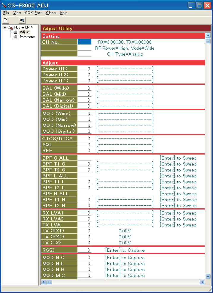
![- FREQUEY JUSTMENT Select an adjustment item using [ ] / [ ] keys, then set to the specified value using [ ] / [ ] keys on the connected P's keyboard.](/docs-images/89/99915922/images/16-0.jpg "JUSTMENT PLL LOK VOLTGE [RX LV] JUSTMENT ONITION hannel Lock voltage preset [LV (RX)] Receiving [RX LV] hannel Lock voltage preset [LV (RX)] Receiving [TX LV] hannel Lock voltage preset [LV (TX)] PLL")
16 - FREQUEY JUSTMENT Select an adjustment item using [ ] / [ ] keys, then set to the specified value using [ ] / [ ] keys on the connected P's keyboard. JUSTMENT PLL LOK VOLTGE [RX LV] JUSTMENT ONITION hannel Lock voltage preset [LV (RX)] Receiving [RX LV] hannel Lock voltage preset [LV (RX)] Receiving [TX LV] hannel Lock voltage preset [LV (TX)] PLL LOK VOLTGE REFEREE FREQUEY [REF] hannel Receiving hannel Receiving hannel : H : [.0 V] : H : [.0 V] : H : [.0 V] UNIT P screen : H P screen : H : H hannel : H Top onnect an RF power meter to the panel antenna connector. MESUREMENT OPERTION lick [I/O heck] in the lone menu to open the "I/O heck window." lick [Update (F)] button, then check the "LVIN" item on the S-F00 J's screen as below. lick [Update (F)] button, then check the "LVIN" item on the S-F00 J's screen. Loosely couple a frequency counter to the antenna connector. VLUE.0 V 0.. V (Verify) MHz I/O heck window -
17 - TRNSMIT JUSTMENT Select an adjustment item using [ ] / [ ] keys, then set to the specified value using [ ] / [ ] keys on the connected P's keyboard. JUSTMENT OUTPUT POWER [Power (Hi)] hannel JUSTMENT ONITION UNIT : H Top panel [Power (L)] hannel [Power (L)] hannel MOULTION hannel : H Top LE Preset [MO Narrow] : 0 panel [L (Narrow)] No audio applied to the JIG cable. Set an FM deviation meter same as; HPF : OFF LPF : 0 khz e-emphasis : OFF etector : (P P)/ Push [P0] key while transmitting. FM hannel : H Top EVITION onnect an audio generator to the JIG panel (NRROW) cable and set as; [MO N ] Frequency :.0 khz Level : 0 mv rms Set the FM deviation meter to same condition as "MOULTION LE." (NRROW) [MO N L] (NRROW) [MO N H] (WIE) [MO W ] (WIE) [MO W L] (WIE) [MO W H] (MILE) [MO M ] (MILE) [MO M L] (MILE) [MO M H] IGITL EVITION* [MO ] hannel hannel hannel hannel hannel hannel hannel hannel MESUREMENT OPERTION onnect an RF power meter to the antenna connector. VLUE.0 W : H.0 W : H.0 W : H : H onnect the FM deviation meter to the antenna connector through an attenuator. onnect the FM deviation meter to the antenna connector through an attenuator. Set to square wave form ±.0 to ±. khz : H ±.0 to ±. khz : H : H : H ±. to ±. khz : H : H Preset [igital Mode] : Top hannel : H panel Set the FM deviation meter to same condition as "MOULTION LE." [MO L] hannel [MO H] hannel TSS/TS EVITION [TSS/TS] : H 0 : H hannel : H Top No audio applied to the JIG cable. panel Set the FM deviation meter to same condition as "MOULTION LE." ; [EUR-0] only. *; Necessary only when the optional UT- is installed. onnect an FM deviation meter to the antenna connector through an attenuator. onnect an FM deviation meter to the antenna connector through an attenuator. ±. to ±. khz ±0. to ±0. khz -
18 - REEIVE JUSTMENT Select an adjustment item using [ ] / [ ] keys, then set to the specified value using [ ] / [ ] keys on the connected P's keyboard. JUSTMENT JUSTMENT ONITION MESUREMENT UNIT LOTION VLUE REEIVE SENSITIVITY NOTE: "REEIVE SENSITIVITY" must be adjusted before "S-METER." Otherwise, "S-METER" will not be adjusted properly. [PF T ] hannel : H Multi onnect the SIN meter Minimum distortion [PF T ] onnect the SSG to the antenna connec- connector with an Ω load to the JIG level cable. [PF T H] [PF T H] [PF T L] [PF T L] S-METER [RSSI] SQUELH [SQL] tor and set as; Frequency Level Modulation eviation Receiving hannel Frequency Receiving hannel Frequency Receiving :.000 MHz : +0 dµ ( dm) : khz : ±. khz : H :.000 MHz : H :.000 MHz ONVENIENT: The "REEIVE SENSITIVITY" can be adjustment automatically. : Put the cursor on "PF T /L/H LL" or "PF T /L/H LL" and then push [ENTER] key. : The connected P tunes PF's to peak levels automaticaly. or : Put the cursor on the one of "PF T /L/H" and "PF T /L/H" as desired. : Push [ENTER] key to start tuning. : Repeat and to perform additional PF tuning. hannel : H Push the [ENTER] key on the connected P's keyboard to set onnect the SSG to the antenna connec- "S" level. tor and set as; Frequency Level Modulation eviation Receiving Set the SSG as; Level Receiving :.000 MHz : + dµ ( dm) : khz : ±. khz : dµ ( dm) hannel : H External lose the squelch by adjusting the value of speaker [SQL] item on the S-F00 J's screen. onnect the SSG to the antenna connector and set as; Frequency Level Modulation eviation Receiving :.000 MHz : dµ ( dm) : khz : ±. khz Push the [ENTER] key on the connected P's keyboard to set "S" level. onnect an Ω speaker to the JIG cable. ; The output level of the standard signal generator (SSG) is indicated as the SSG's open circuit. Set the [SQL] to the value that the audio signals just appears. -
19 SETION PRTS LIST I-F0/F0/F0/T/S [FRONT UNIT] REF ORER H/V ESRIPTION M. LOTION I S.REG S-0M-K-G./. I S.I M0FP FJ /. I S.I M0FP FJ./. I S.I TTS/N./. I S.I NJM0V-TE./. Q S.TR S T00 R./ Q S.TR XP0-(TX)../0. Q S.TR UMGN TL./ Q S.TR UNRJ-(TX)./ Q S.TR UNRJ-(TX)./. Q S.TR TEU T0./ Q S.TR TEK T./. Q 0000 S.TR UNRJ-(TX) / Q 0000 S.TR UNRJ-(TX)./. Q 0000 S.TR UNRJ-(TX)./. Q 0000 S.FET SK0 TL /. Q 0000 S.TR UNRJ-(TX) 0./ S.IO MS-(TX) / S.IO MS-(TX)./ S.IO MS-(TX) / S.IO P TL./ S.IO P TL./ S.IO N0U T0./. R S.RES ERJGEJ X (. k /0 R S.RES ERJGEJ X ( k./. R S.RES ERJGEJ 0 X ( k./. R S.RES ERJGEJ 0 X ( k./. R S.RES ERJGEJ 0 X (0 k./. R S.RES ERJGEJ 0 X (0 k./. R S.RES ERJGEJ X ( k./. R S.RES ERJGEJ 0 X (00 k./. R S.RES ERJGEJ 0 X (0 k./. R S.RES ERJGEJ X ( k./. R S.RES ERJGEJ X ( k./ R S.RES ERJGEJ 0 X (00 k./. R S.RES ERJGEJ 0 X ( k./. R S.RES ERJGEJ 0 X ( k./. R S.RES ERJGEJ 0 X (0 k./. R S.RES ERJGEJ 0 X (0 k./0. R S.RES ERJGEJ 0 X (0 k./. R S.RES ERJGEJ 0 X (00 k./. R S.RES ERJGEJ 0 X (00 k./. R S.RES ERJGEJ 0 X (00 k./. R S.RES ERJGEJ 0 X (00 k./. R S.RES ERJGEJ 0 X (00 k./. R S.RES ERJGEJ 0 X (00 k./. R S.RES ERJGEJ 0 X (00 k./. R S.RES ERJGEJ 0 X (00 k /. R S.RES ERJGEJ X (0)./. R S.RES ERJGEJ X (0)./ R S.RES ERJGEJ 0 X (00 k./ R S.RES ERJGEJ 0 X ()./. R S.RES ERJGEJ 0 X ()./. R S.RES ERJGEJ 0 X ()./. R S.RES ERJGEJ 0 X ()./. R S.RES ERJGEJ 0 X ( k./. R S.RES ERJGEJ 0 X ( k /. R S.RES ERJGEJ 0 X (0 k./. R S.RES ERJGEJ X ( k 0./0. R S.RES ERJGEJ 0 X (00 k./0. R S.RES ERJGEJ X ( k./. R S.RES ERJGEJ X ( k./. R S.RES ERJGEJ 0 X (00)./. R S.RES ERJGEJ X [0-key type] only./. R S.RES ERJGEJ X [0-key type] only./. R S.RES ERJGEJ X (0 k./. R S.RES ERJGEJ 0 X (00 k./0. R S.RES ERJGEJ 0 X (00 k R [-key type] only / S.RES ERJGEJ 0 X (00 k [0-key type] only./ R S.RES ERJGEJ 0 X (0 k./. R S.RES ERJGEJ 0 X () /. R S.RES ERJGEJ X (. k./. R S.RES ERJGEJ X (. k./. R S.RES ERJGEJ X (. k./. R S.RES ERJGEJ X (0)./. [FRONT UNIT] REF ORER H/V ESRIPTION M. LOTION R S.RES ERJGEJ X (0)./0. R S.RES ERJGEJ 0 X (0 k 0./. R S.RES ERJGEJ 0 X (0 k./. R S.RES ERJGEJ-JPW./0. R S.RES ERJGEJ 0 X (00 k / S.TN TEESVMR./ S.TN TEESVMR./ S.TN TEESV 0MR./ S.TN TEESV 0MR 0./ S.TN TEESV 0MR 0./ S.ER EJ0EE0K./ S.ER EJ0E0K./ S.ER EJ0EE0K./ S.TN TEESV 0MR./ S.ER EJ0E0K 0./ S.ER EJ0E0K 0/ S.ER EJ0EE0K./ S.ER EJ0EE0K / S.ER EJ0E0K./ S.ER EJ0E0K 0/ 0000 S.ER EJ0EE0K./ S.ER EJ0E0K 0./ 0000 S.ER EJ0EE0K 0./ S.ER EJ0EE0K./ S.ER EJ0E0K 0/ S.ER EJ0E0K / S.ER EJ0EE0K 0/ S.ER EJ0EE0K./ S.TN TEESV MR./ S.ER EJ0E0K./ S.ER EJ0E0K./ S.TN TEESV MR / S.ER EJ0E0K / S.TN TEESV 0MR./ S.ER EJ0E0K./ S.ER EJ0EHK./ S.ER EJ0E0K./ S.ER EJ0EHJ./ S.TN TEESV 0MR./ 0000 S.ER EJ0EE0K./ S.ER EJ0E0K T./ S.ER EJ0EEK./ S.ER EJ0E0K./. J0 000 S.NR IMS-S-0Y./. J0 000 S.NR IMS-S-0Y./. J0 000 S.NR IMS-S-0Y./. S S.LE SML-MT T T./. S S.LE SML-MT T T./. S S.LE SML-MT T T./. S S.LE SML-0MT T T./. S S.LE SML-0MT T T./0. S S.LE SML-0MT T [0-key type] only T./. S S.LE SML-0MT T [0-key type] only T./. S S.LE SML-0MT T [0-key type] only T./. S S.LE SML-0MT T [0-key type] only T./. S L M-00TY- M MI SK- LP W WIR /0/00/W0/W0 W WIR /00/0/W0/W0 M.=Mounted side (T: Mounted on the Top side, : Mounted on the ottom side) S.=Surface mount -
20 [MIN UNIT] REF ORER H/V ESRIPTION M. LOTION I S.I LMXTMX/NOP./. I 000 S.I TFNG ( EL)./. I 0000 S.I MFP 00./. I 000 S.I KP-E/P./. I 0000 S.I NJM0F0-TE./0. I 000 S.I S-0NM-GTG./. I 0000 S.I NJM0V-TE./ I0 000 S.I UFS-E./. I 0000 S.I 0PWR./. I 0000 S.I 0PWR./. I 0000 S.I NMS T 0./. I 0000 S.I NJM0V-TE./. I 000 S.I HFTF0V /. I 000 S.I LT-I/SM /. I S.I MFP 00 T./. I 0000 S.I NJMF-TE./. I 0000 S.I 0PWR./. I 000 S.I 0PWR./. Q 0000 S.TR S-T R T 0./. Q 0000 S.TR S-T R T./. Q 0000 S.TR S-T R T./. Q 000 S.TR S0-O (TER F) T 0/. Q 000 S.TR S0-O (TER F)./. Q 0000 S.TR S-T R./. Q 000 S.TR S0-O (TER F)./. Q S.FET SK (TEL F) T 00./0 Q S.FET SK (TER) [US-0], [GEN-0]./ S.FET SK (TER F) [others]./. Q S.TR S T00 R T./. Q 0000 S.TR XP0-(TX). T 0./. Q S.TR S T0 Q./. Q S.TR S T0 Q 0./. Q S.TR S T0 Q T 0./. Q 000 S.TR S-L (TER F)./. Q 000 S.TR S-L (TER F)./. Q S.TR XP (TX)./. Q S.TR XP (TX)./0. Q 0000 S.TR UNRJ-(TX)./ Q 0000 S.TR UNRJ-(TX)./ Q 0000 S.TR S-O (TER F)./. Q 0000 S.TR UNRJ-(TX)./. Q 0000 S.TR UNRJ-(TX) /. Q 0000 S.TR XP0 (TX)./. Q0 000 S.FET TP0 (TEL F) 0./. Q 0000 S.TR UNRJ-(TX) T./. Q 0000 S.FET SK0 TL./ Q 0000 S.FET SK0-Y (TRIOM F)./. Q 0000 S.TR UNRJ-(TX)./. Q 0000 S.TR UNRJ-(TX) T./. Q S.FET SKUG-TL-E T./ Q 000 S.TR S-L (TER F) T./. Q 000 S.TR S-L (TER F) T./ Q 000 S.TR S-L (TER F)./. Q 0000 S.TR UNRJ-(TX)./0. Q 0000 S.FET SK0 TL T./ Q 0000 S.TR UNRJ-(TX) T./ S.VP HVTRF-E T./ S.VP HVTRF-E T 0./ S.VP SV (TPH) [US-0], [GEN-0] T./ S.VP SV (TPH F) [others] T./ S.VP SV (TPH) [US-0], [GEN-0] T./ S.VP SV (TPH F) [others] T./ S.VP SV (TPH) [US-0], [GEN-0] T./ S.VP SV (TPH F) [others] T./ S.VP SV (TPH) [US-0], [GEN-0] T./ S.VP SV (TPH F) [others] T./ S.VP HVTRF-E T./ S.VP HVTRF-E T./ S.VP SV (TPH F) T./ S.VP HVTRF-E T./ S.VP HVTRF-E T./ S.VP HVTRF-E T./ 0000 S.IO MS-(TX)./ S.IO SV0 (TPL F)./ S.IO MS0-(TX) T./ 0000 S.IO MS-(TX)./ S.IO MS0-(TX)./ S.VP HVTRF-E T 0./ S.VP HVTRF-E T 0./ S.IO MS-(TX) 0./ S.IO TL./ S.IO TL 00./ S.VP HV0TRF-E T./. [MIN UNIT] REF ORER H/V ESRIPTION M. LOTION 0000 S.VP HV0TRF-E T./ S.IO MS0-(TX)./ S.IO MS0-(TX)./ S.IO NETL T 0./ S.IO NETL T 0./ S.IO NETL 0./ S.IO NETL./ S.IO N0U T0 T./ S.ZEN M0-M (TX) T./ S.IO MS0-(TX)./ S.IO P0U T0./ 0000 S.IO MS-(TX) / S.IO P TL T./. FI S.MLH FL-0 (. MHz) T./. FI S.ER FW0KGF-R0 T /. FI S.ER FWK0KHF-R0 T./. FI S.MLH FL- (.0 MHz)./. X 0000 S.XTL R- (. MHz)./. X 0000 S.XTL R- (.0 MHz) T./. X 0000 S.XTL R- (. MHz) T./. X 0000 S.XTL R- (.0 MHz) T./. X S.R 0KY-R0 T./. L S.OL MLF0 RK-T./ L S.OL MLF0 RK-T T./ L S.OL MLF0 RK-T T./. L S.OL MLF0 RK-T T./. L S.OL MLF0E 00K-T T./ L S.OL MLF0 RK-T T./0 L S.OL LQWHNNJ0L T./. L 0000 S.OL TL 0.N T./. L S.OL MLF0E 00K-T T /. L S.OL MLF0 RK-T T./. L S.OL 0.-.-TL 0N T./. L S.OL MLF0E 00K-T T 0./. L S.OL LQWHNNJ0L T./. L S.OL MLF0 RK-T T 0./. L 0000 S.OL ELJRE R0GF T 0./ L 0000 S.OL ELJRF NJF./. L S.OL ELJRE RGF./. L 0000 S.OL ELJRE NGF 0./. L S.OL LQWHNNJ0L 00./. L S.OL LQWHNNJ0L T 0./. L S.OL LQWHNNJ0L T 0./ L S.OL LQWHNNJ0L T /. L S.OL LQWHNNJ0L T./. L 0000 S.OL ELJRE NGF T./. L 0000 S.OL ELJRE NGF T./. L S.OL ELJRF NJF./. L S.OL MLF0 RK-T./ L S.OL MLF0 RK-T./0. L S.OL ELJ RK-F./. L S.OL ELJRF R0JF./. R S.RES ERJGEJ X (0 k./. R S.RES ERJGEJ 0 X (0 k./. R S.RES ERJGEJ X (0 k./. R S.RES ERJGEJ X (0) T./. R S.RES ERJGEJ X (0 k./. R 0000 S.RY EXV0JX /. R S.RES ERJGEJ-JPW /0. R S.RES ERJGEJ X (. k./. R S.RES ERJGEJ X ( k./. R S.RES ERJGEJ X (. k./0. R S.RES ERJGEJ-JPW T./. R S.RES RR00P-- (. k T./. R S.RES RR00P-- (. k T./0. R S.RES RR00P-- (. k T./. R S.RES RR00P-- (. k T./. R S.RES ERJGEJ-JPW T./. R S.RES RR00P-- (. k T./. R S.RES RR00P-- (. k T./. R S.RES ERJGEJ-JPW T./. R S.RES ERJGEJ X (0) T./. R S.RES ERJGEJ X (0) T./. R S.RES ERJGEJ X (0) T / R S.RES ERJGEJ 0 X (0 k./ R S.RES ERJGEJ X ( k 0./0. R S.RES ERJGEJ X ( k./. R S.RES ERJGEJ X (. k./. R S.RES ERJGEJ 0 X (00 k T /. R S.RES ERJGEJ 0 X (00) T./0. R S.RES ERJGEJ X ( k 0./. R S.RES ERJGEJ 0 X (00) 0./. R S.RES ERJGEJ R X (.)./. R S.RES ERJGEJ 0 X (00 k./. M.=Mounted side (T: Mounted on the Top side, : Mounted on the ottom side) S.=Surface mount -
21 [MIN UNIT] REF ORER H/V ESRIPTION M. LOTION R S.RES ERJGEJ 0 X (00)./. R S.RES ERJGEJ-JPW./. R S.RES ERJGEJ X (. k./. R S.RES ERJGEJ 0 X (00)./. R S.RES ERJGEJ 0 X (0 k./. R S.RES ERJGEJ 0 X (00 k T 0./. R S.RES ERJGEJ 0 X (00 k T 0./. R S.RES ERJGEJ 0 X (0 k T 0./. R S.RES ERJGEJ 0 X (00 k T 0./. R S.RES ERJGEJ X (0 k T 0./. R S.RES ERJGEJ X (0) T./. R S.RES ERJGEJ 00 X (0) T 0./. R S.RES ERJGEJ X (0 k 0./. R S.RES ERJGEJ X (. k./. R S.RES ERJGEJ X (0 k 0./. R S.RES ERJGEJ X (0 k 0./ R S.RES ERJGEJ X ( k./. R S.RES ERJGEJ R X (.)./. R S.RES ERJGEJ 0 X ()./. R S.RES ERJGEJ X (0) T./. R S.RES ERJGEJ 0 X (00 k T./. R S.RES ERJGEJ 0 X (00 k T./. R S.RES ERJGEJ 0 X (0 k T./. R S.RES ERJGEJ 0 X (0 k T /. R S.RES ERJGEJ 0 X (00) T /. R S.RES ERJGEJ 0 X () T./. R S.RES ERJGEJ X (. k./. R S.RES ERJGEJ X (. k 0./. R S.RES ERJGEJ X (. k./. R S.RES ERJGEJ 0 X (00 k./. R S.RES ERJGEJ X (0)./. R S.RES ERJGEJ 0 X (00)./. R S.RES ERJGEJ 0 X (00 k./. R S.RES ERJGEJ X (. k T./. R S.RES ERJGEJ X (. k./. R S.RES ERJGEJ 0 X ()./. R S.RES ERJGEJ X ( k 0./. R S.RES ERJGEJ X (. k T./. R S.RES ERJGEJ-JPW T 0./. R S.RES ERJGEJ X (. k T./. R S.RES ERJGEJ X (. k T./. R S.RES ERJGEJ X (0 k /. R S.RES ERJGEJ X (. k./. R S.RES ERJGEJ X ( k T 0./. R S.RES ERJGEJ X (0) 0/. R S.RES ERJGEJ 0 X (0 k./. R S.RES ERJGEJ X ( k./ R S.RES ERJGEJ X (. k T /0. R S.RES ERJGEJ X (. k./. R S.RES ERJGEJ X (. k./. R S.RES ERJGEJ X (. k T./ R S.RES ERJGEJ X ( k./. R S.RES ERJGEJ 0 X (00 k./ R S.RES ERJGEJ X (0) /. R S.RES ERJGEJ 0 X (00 k./. R S.RES ERJGEJ X (. k./. R S.RES ERJGEJ X (0 k./. R S.RES ERJGEJ X (0 k /0. R S.RES ERJGEJ 0 X ( M T /. R S.RES ERJGEJ X (. k./. R S.RES ERJGEJ 0 X (00 k./. R S.RES ERJGEJ X ( k /. R S.RES ERJGEJ X (. k./. R S.RES ERJGEJ X ( k./. R S.RES ERJGEJ 0 X (0 k./. R S.RES ERJGEJ X (. k./ R S.RES ERJGEJ X ( k./. R S.RES ERJGEJ X ( k./ R S.RES ERJGEJ X ( k./ R S.RES ERJRKF 00 (0 k./. R 0000 S.RES ERJRKF 0 ( k./. R 0000 S.RES ERJRKF 00 (0 k./ R 0000 S.RES ERJRKF 0 ( k T./. R S.RES ERJGEJ 0 X ( k./ R S.RES ERJGEJ X (. k T /0. R S.RES ERJGEJ-JPW T /. R S.RES ERJGEJ X (0 k T./. R S.RES ERJGEJ X ( k T./. R S.RES ERJGEJ X ( k T./. R S.RES ERJGEJ X (0)./. R S.RES ERJGEJ X (0) T./. R S.RES ERJGEJ 0 X ( M T /. R S.RES ERJGEJ X ( k T./. R S.RES ERJGEJ 0 X (00 k T./. R S.RES ERJGEJ 0 X (00 k./ R S.RES ERJGEJ X (. k./. R S.RES ERJGEJ X ( k./. R S.RES ERJGEJ X ( k./. R S.RES ERJGEJ 0 X (00 k./. R S.RES ERJGEJ-JPW /. R S.RES ERJGEJ X ( k./. R S.RES ERJGEJ X ( k T./. [MIN UNIT] REF ORER H/V ESRIPTION M. LOTION R S.RES ERJGEJ X (0 k T./. R S.RES ERJGEJ X (. k./. R S.RES ERJGEJ X (. k./. R S.RES ERJGEJ X ( k./. R S.RES ERJGEJ X (. k./. R 0000 S.RES ERJGEJ X ( k./0. R S.RES ERJGEJ 0 X (00) T./. R S.RES ERJGEJ 0 X ( M T./. R S.RES ERJGEJ X (. k T./. R S.RES ERJGEJ X (0) T 0./. R S.RES ERJGEJ X ( k./. R S.RES ERJGEJ X ( k./0. R S.RES ERJGEJ X ( k T./0. R S.RES ERJGEJ X ( k T 0./. R S.RES ERJGEJ X (0 k./. R 0000 S.RES ERJRKF 0 (0 k T./. R S.RES ERJGEJ-JPW 0./. R S.RES ERJGEJ X (0 k./ R S.RES ERJGEJ X (. k./. R S.RES ERJGEJ X (0 k./. R S.RES ERJGEJ X ( k /. R S.RES ERJGEJ-JPW./. R S.RES ERJGEJ X (0 k./. R S.RES ERJGEJ 0 X (00 k /. R S.RES ERJGEJ 0 X (0 k T 0/. R S.RES ERJGEJ 0 X (00) T./. R S.RES ERJGEJ X (. k T./. R S.RES ERJGEJ 0 X (0 k./. R S.RES ERJGEJ X (. k./. R S.RES ERJGEJ 0 X (0 k 0./. R S.RES ERJGEJ X (. k./. R S.RES ERJGEJ 0 X (0 k T./. R S.RES ERJGEJ X (. k T 0./. R S.RES ERJGEJ X (0 k./. R S.RES ERJGEJ X (0 k 0./. R S.RES ERJGEJ 0 X ( k /. R S.RES ERJGEJ X (0) T 0./. R S.RES ERJGEJ 0 X (0 k T./. R S.RES ERJGEJ X (. k./. R S.RES ERJGEJ X ( k./. R S.RES ERJGEJ X ( k./. R S.RES ERJGEJ X ( k./. R S.RES ERJGEJ X (0 k T./. R S.RES ERJGEJ X ( k./. R S.RES ERJGEJ X ( k./. R S.RES ERJGEJ X ( k./. R S.RES ERJGEJ X ( k 0./. R S.RES ERJGEJ X ( k 0./0. R S.RES ERJGEJ X ( k./. R S.RES ERJGEJ 0 X (00) T./0. R S.RES ERJGEJ X ( k./. R 0000 S.RY EXV0JX./. R 0000 S.RY EXV0JX T 0./0. R 0000 S.RY EXV0JX./. R 0000 S.RY EXV0JX /. R 0000 S.RY EXV0JX./. R 0000 S.RY EXV0JX T./. R S.RES ERJGEJ X (0) T 0./. R S.RES ERJGEJ 0 X (0 k./. R S.RES ERJGEJ 0 X (00 k./. R S.RES ERJGEJ 0 X (0 k T 0./. R 0000 S.RY EXV0JX T./. R 0000 S.RY EXV0JX./. R 0000 S.RY EXV0JX T./. R S.RES ERJGEJ 0 X ( k./. R S.RES ERJGEJ 0 X (00)./. R S.RES ERJGEJ 0 X (00 k T./. R S.RES ERJGEJ 0 X (00 k T./. R S.RY EX-VV 0JV ( k./0. R S.RES ERJGEJ 00 X (0) T./. R S.RES ERJGEJ 0 X ( M T./. R S.RES ERJGEJ X ( k./0. R S.RES ERJGEJ X ( k./. R S.RES ERJGEJ X ( k 0./. R S.RES ERJGEJ 0 X ( k T./. R S.RES ERJGEJ 0 X (00 k T./. R S.RES ERJGEJ 0 X (0 k T./. R S.RES ERJGEJ 0 X (00 k T./0. R 0000 S.RY EXV0JX T./. R S.RES ERJGEJ 0 X ( k./. R S.RY EX-VV 0JV ( k T./0. R S.RES ERJGEJ 0 X ( k./. R 0000 S.RY EXV0JX./. R 0000 S.RY EXV0JX T./. R 0000 S.RY EXV0JX./. R S.RES ERJGEJ-JPW./. R S.RES ERJGEJ X ( k T./. R S.RES ERJGEJ 0 X (0 k./. R S.RES ERJGEJ X (0 k T./. R S.RES ERJGEJ X ( k T./. R S.RES ERJGEJ X ( k T./ R S.RES ERJGEJ 0 X ( k T./. M.=Mounted side (T: Mounted on the Top side, : Mounted on the ottom side) S.=Surface mount -
SERVICE MANUAL VHF/UHF FM TRANSCEIVER VHF/UHF DIGITAL TRANSCEIVER
 SERVIE MANUAL VHF/UHF FM TRANSEIVER VHF/UHF DIGITAL TRANSEIVER S-0HZ- May. 00 INTRODUTION This service manual describes the latest service information for the I-9A VHF/UHF FM TRANSEIVER, I-9AD VHF/UHF
Studio Transmitter Link
 UHF STL TRANSMITTER BPT-V/UHF TRANSMITTER SPECIFICATIONS TYPE solid state direct FM frequency synthesised crystal referenced thermal compensated FREQUENCY STABILITY better than 4 ppm0 -------------------------------------------+40
VHF MARINE TRANSCEIVER
 VHF MARINE TRANSCEIVER S-499XZ-C April 203 INTRODUCTION CAUTION This service manual describes the latest technical information for the IC-M73, IC-M73EURO VHF MARINE TRANSCEiVER, at the time of publication.
3%26)#% -!.5!, 6(& ic-v82
#% -!.5!, 6(& ic-v82") i-v8 TABLE OF ONTENTS SETION SPEIFIATIONS SETION INSIDE VIEWS SETION DISASSEMBLY INSTRUTIONS SETION IRUIT DESRIPTION - REEIVER IRUITS... - - TRANSMITTER IRUITS... - - PLL IRUITS... - - OTHER IRUITS...
i-v8 TABLE OF ONTENTS SETION SPEIFIATIONS SETION INSIDE VIEWS SETION DISASSEMBLY INSTRUTIONS SETION IRUIT DESRIPTION - REEIVER IRUITS... - - TRANSMITTER IRUITS... - - PLL IRUITS... - - OTHER IRUITS...
AKC Spectrum Analyzer User s Manual.
 AKC-1291 Spectrum Analyzer User s Manual u ano un ao Prohibiting to removal the cover e m Keep the power insert clean RF in/output rating oae o n DC Power nt Restore this instrument 1. Introduction 2.
SERVICE MANUAL UHF TRANSCEIVERS
 SERVIE MANUAL UHF TRANSEIVERS INTRODUTION This ser vice manual descr ibes the latest ser vice information for the I-F/I-FS/I-F/I-FS UHF TRANSEIVER at the time of publication. MODEL VERSION SYMBOL H FREQUENY
RT-178 / ARC-27 All schematics
 RT / ARC All schematics J I K P0 L A B M C P N D O E H G F P0 RT /ARC F L P0 A C D G J M P S B E K R H N SQ OFF GUARD REC MOD I k I B E i DRVR I g FINAL I g I ant SQ OFF MAIN REC SENS PHONE METER MIC SENS
SERVICE MANUAL SURVIVAL CRAFT 2-WAY RADIO
 SRVI MANUAL SURVIVAL RAFT -WAY RADIO INTRODUTION This service manual describes the latest service information for the I-GM00/ VHF MARIN TRANSIVR at the time of publication. MODL VRSION TX Hi-POWR I GM00
Monolithic Crystal Filters (M.C.F.)
") Monolithic Crystal Filters (M.C.F.) MCF (MONOLITHIC CRYSTAL FILTER) features high quality quartz resonators such as sharp cutoff characteristics, low loss, good inter-modulation and high stability over
Monolithic Crystal Filters (M.C.F.) MCF (MONOLITHIC CRYSTAL FILTER) features high quality quartz resonators such as sharp cutoff characteristics, low loss, good inter-modulation and high stability over
FM TRANSCEVERS S-14315XZ-C1 Jan. 2007
 FM TRNSVRS S-45XZ- Jan. 007 INTRODUTION This service manual describes the latest service information for the I-V85, I-V85 and I-V85-T FM TRNSIVRS at the time of publication. MODL VRSION SYMOL U.S.. [US]
SERVICE MANUAL. DUAL BAND FM TRANSCEIVER i2725e
 SERVIE MANUAL DUAL AND FM TRANSEIVER i7e INTRODUTION This service manual describes the latest service information for the I-7E DUAL AND FM TRANSEIVER at the time of publication MODEL I-7E VERSION Europe
Electrical Specifications at T AMB =25 C DC VOLTS (V) MAXIMUM POWER (dbm) DYNAMIC RANGE IP3 (dbm) (db) Output (1 db Comp.) at 2 f U. Typ.
 MAXIMUM POWER (dbm) DYNAMIC RANGE IP3 (dbm) (db) Output (1 db Comp.) at 2 f U. Typ.") Surface Mount Monolithic Amplifiers High Directivity, 50Ω, 0.5 to 5.9 GHz Features 3V & 5V operation micro-miniature size.1"x.1" no external biasing circuit required internal DC blocking at RF input &
Surface Mount Monolithic Amplifiers High Directivity, 50Ω, 0.5 to 5.9 GHz Features 3V & 5V operation micro-miniature size.1"x.1" no external biasing circuit required internal DC blocking at RF input &
VHF MOBILE TRANSCEIVERS
 VHF MOBILE TRANSCEIVERS S-44XZ-C Feb. 009 INTRODUCTION This service manual describes the latest technical information for the IC-F0 IC-F0 IC-F0/H IC-F06/H IC-F08H VHF MOBILE TRANSCEIVERS at the time of
SERVICE MANUAL. VHF MARINE TRANSCEIVER im602
 SERVIE MANUAL VHF MARINE TRANSEIVER im0 INTRODUTION This service manual describes the latest service information for the I-M0 VHF MARINE TRANSEIVER at the time of publication. MODEL I-M0 VERSION USA USA-
SERVICE MANUAL. VHF MARINE TRANSCEIVER ic-m422
 SERVICE MANUAL VHF MARINE TRANSCEIVER ic-m S-MZ-C-q Jul. 00 INTRODUCTION This service manual describes the latest service information for the IC-M VHF MARINE TRANSCEIVER at the time of publication. MODEL
DUAL BAND FM TRANSCEIVER. ic-2800h
 DUAL AND FM TRANSCEIVER ic-00h INTRODUCTION This service manual describes the latest service information for the IC-00H FM TRANSCEIVER at the time of publication. MODEL VERSION SYMOL IC-00H Europe Italy
COMMUNICATIONS RECEIVERS. ic-r1500 ic-r2500
 COMMUNICATIONS RECEIVERS ic-r ic-r S-MZ-C Jun. INTRODUCTION This service manual describes the latest service information for the IC-R and IC-R COMMUNICATIONS RECEIVERS at the time of publication. MODEL
SPBW06 & DPBW06 series
 /,, MODEL SELECTION TABLE INPUT ORDER NO. INPUT VOLTAGE (RANGE) NO LOAD INPUT CURRENT FULL LOAD VOLTAGE CURRENT EFFICIENCY (TYP.) CAPACITOR LOAD (MAX.) SPBW06F-03 310mA 3.3V 0 ~ 1500mA 81% 4700μF SPBW06F-05
SERVICE MANUAL. HF/ 50MHz ALL MODE TRANSCEIVER i703
 SERVICE MANUAL HF/ 0MHz ALL MODE TRANSCEIVER i0 INTRODUCTION This service manual describes the latest service information for the IC0 HF/0MHz ALL MODE TRANSCEIVER. MODEL IC0 VERSION Europe France Spain
SERVICE MANUAL. ic-f3 ic-f3s. ic-f4 ic-f4s VHF FM TRANSCEIVERS UHF FM TRANSCEIVERS
 SERVICE MANUAL VHF FM TRANSCEIVERS ic-f ic-fs UHF FM TRANSCEIVERS ic-f ic-fs INTRODUCTION This service manual describe the latest information for the IC-F/IC-FS and IC-F/IC-FS at the time of publication.
Instruction Execution Times
 1 C Execution Times InThisAppendix... Introduction DL330 Execution Times DL330P Execution Times DL340 Execution Times C-2 Execution Times Introduction Data Registers This appendix contains several tables
MAX4147ESD PART 14 SO TOP VIEW. Maxim Integrated Products 1 MAX4147 EVALUATION KIT AVAILABLE ; Rev 1; 11/96 V CC V EE OUT+ IN+ R t SENSE IN-
 -; Rev ; / EVALUATION KIT AVAILABLE µ µ PART ESD TEMP. RANGE - C to +5 C PPACKAGE SO TOP VIEW V EE V CC SENSE+ SENSE- R t R t R t R t MAX SENSE OUT SENSE+ SENSE- N.C. SHDN N.C. 3 5 R f R G R f 3 VDSL TRANSFORMER
ΜΕΛΕΤΗ ΚΑΙ ΠΡΟΣΟΜΟΙΩΣΗ ΙΑΜΟΡΦΩΣΕΩΝ ΣΕ ΨΗΦΙΑΚΑ ΣΥΣΤΗΜΑΤΑ ΕΠΙΚΟΙΝΩΝΙΩΝ.
 Τµήµα Ηλεκτρονικής ΜΕΛΕΤΗ ΚΑΙ ΠΡΟΣΟΜΟΙΩΣΗ ΙΑΜΟΡΦΩΣΕΩΝ ΣΕ ΨΗΦΙΑΚΑ ΣΥΣΤΗΜΑΤΑ ΕΠΙΚΟΙΝΩΝΙΩΝ. Σπουδαστής: Γαρεφαλάκης Ιωσήφ Α.Μ. 3501 Επιβλέπων καθηγητής : Ασκορδαλάκης Παντελής. -Χανιά 2010- ΠΕΡΙΛΗΨΗ : Η παρούσα
65W PWM Output LED Driver. IDLV-65 series. File Name:IDLV-65-SPEC
 ~ A File Name:IDLV65SPEC 07050 SPECIFICATION MODEL OUTPUT OTHERS NOTE DC VOLTAGE RATED CURRENT RATED POWER DIMMING RANGE VOLTAGE TOLERANCE PWM FREQUENCY (Typ.) SETUP TIME Note. AUXILIARY DC OUTPUT Note.
VHF/UHF DIGITAL TRANSCEIVER
 VHF/UHF DIGITAL TRANSCEIVER S-48XZ-C Apr. 009 INTRODUCTION This service manual describes the latest technical information for the IC-80AD and IC-E80D VHF/UHF DIGITAL TRANSCEIVER at the time of publication.
[1] P Q. Fig. 3.1
![[1] P Q. Fig. 3.1](/thumbs/79/80362156.jpg "[1] P Q. Fig. 3.1") 1 (a) Define resistance....... [1] (b) The smallest conductor within a computer processing chip can be represented as a rectangular block that is one atom high, four atoms wide and twenty atoms long. One
1 (a) Define resistance....... [1] (b) The smallest conductor within a computer processing chip can be represented as a rectangular block that is one atom high, four atoms wide and twenty atoms long. One
Surface Mount Multilayer Chip Capacitors for Commodity Solutions
 Surface Mount Multilayer Chip Capacitors for Commodity Solutions Below tables are test procedures and requirements unless specified in detail datasheet. 1) Visual and mechanical 2) Capacitance 3) Q/DF
the total number of electrons passing through the lamp.
 1. A 12 V 36 W lamp is lit to normal brightness using a 12 V car battery of negligible internal resistance. The lamp is switched on for one hour (3600 s). For the time of 1 hour, calculate (i) the energy
RSDW08 & RDDW08 series
 /,, MODEL SELECTION TABLE INPUT ORDER NO. INPUT VOLTAGE (RANGE) NO LOAD INPUT CURRENT FULL LOAD VOLTAGE CURRENT EFFICIENCY (Typ.) CAPACITOR LOAD (MAX.) RSDW08F-03 344mA 3.3V 2000mA 80% 2000μF RSDW08F-05
Installer ar505eng.exe
 GUIDE FOR CD ) COMPOSION PCR_ PCR_.pdf FYC PCR Aformat.pdf PCR Aformat.pdf PCR MANUAL.pdf Installer areng.exe README.txt ) DESCRIPTION PCR_.pdf The service manual for IC-PCR and IC-PCR including all service
High Performance Voltage Controlled Amplifiers Typical and Guaranteed Specifications 50 Ω System
 High Performance Voltage Controlled Amplifiers Typical and Guaranteed Specifications 50 Ω System Typical and guaranteed specifications vary versus frequency; see detailed data sheets for specification
65W PWM Output LED Driver. IDPV-65 series. File Name:IDPV-65-SPEC
 IDPV65 series ~ A File Name:IDPV65SPEC 07060 IDPV65 series SPECIFICATION MODEL OUTPUT OTHERS NOTE DC VOLTAGE RATED CURRENT RATED POWER DIMMING RANGE VOLTAGE TOLERANCE PWM FREQUENCY (Typ.) SETUP TIME Note.
Summary of Specifications
 Snap Mount Large High CV High Ripple 85 C Temperature The series capacitors are the standard 85 C, large capacitance, snap-in capacitors from United Chemi-Con. The load life for the series is 2,000 hours
SPEEDO AQUABEAT. Specially Designed for Aquatic Athletes and Active People
 SPEEDO AQUABEAT TM Specially Designed for Aquatic Athletes and Active People 1 2 Decrease Volume Increase Volume Reset EarphonesUSBJack Power Off / Rewind Power On / Fast Forward Goggle clip LED Status
Modbus basic setup notes for IO-Link AL1xxx Master Block
 n Modbus has four tables/registers where data is stored along with their associated addresses. We will be using the holding registers from address 40001 to 49999 that are R/W 16 bit/word. Two tables that
DC-DC Constant Current Step-Down LED driver LDD-300L LDD-350L LDD-500L LDD-600L LDD-700L CURRENT RANGE
 SPECIFICATION ORDER NO. LDD-00L LDD-0L LDD-00L LDD-00L LDD-700L CURRENT RANGE 00mA 0mA 00mA VOLTAGE RANGE Note. ~ VDC for LDD-00~700L/LW ; ~ 8VDC for LDD-00~700LS CURRENT ACCURACY (Typ.) ±% at VDC input
SERVICE MANUAL VHF AIR BAND TRANSCEIVERS
 SERVICE MANUAL VHF AIR BAND TRANSCEIVERS S-20HZ-C May. 2005 INTRODUCTION This service manual describes the latest service information for the IC-A22/E and IC-A3/E VHF AIR BAND TRANSCEIVERS at the time
38BXCS STANDARD RACK MODEL. DCS Input/Output Relay Card Series MODEL & SUFFIX CODE SELECTION 38BXCS INSTALLATION ORDERING INFORMATION RELATED PRODUCTS
 DCS Input/Output Relay Card Series STANDARD RACK MODEL 38BXCS MODEL & SUFFIX CODE SELECTION 38BXCS MODEL CONNECTOR Y1 :Yokogawa KS2 cable use Y2 :Yokogawa KS9 cable use Y6 :Yokogawa FA-M3/F3XD32-3N use
Potential Dividers. 46 minutes. 46 marks. Page 1 of 11
 Potential Dividers 46 minutes 46 marks Page 1 of 11 Q1. In the circuit shown in the figure below, the battery, of negligible internal resistance, has an emf of 30 V. The pd across the lamp is 6.0 V and
SERVICE MANUAL. HF TRANSCEIVER if7000
 SERVICE MANUAL HF TRANSCEIVER if7000 INTRODUCTION This service manual describes the latest service information for the IC-F7000 HF TRANSCEIVER at the time of publication. DANGER NEVER connect the transceiver
UHF TRANSCEIVERS S-14617XZ-C1 Nov. 2009
 UHF TRANSCEIVERS S-467XZ-C Nov. 2009 INTRODUCTION This service manual describes the latest technical information for the IC-F400/IC-F4002/IC-F4003/IC-F4006/ IC-F4008 UHF TRANSCEIVERS at the time of publication.
COMPONENTS LIST BASE COMPONENTS
 ITLIN TEHNOLOGY grifo PPENIX : R SSEMLY The GP F can be ordered in two different mode: completely mounted, tested and ready to use or in assembly kit. In this final condition the user can directly use
Εγκατάσταση λογισμικού και αναβάθμιση συσκευής Device software installation and software upgrade
 Για να ελέγξετε το λογισμικό που έχει τώρα η συσκευή κάντε κλικ Menu > Options > Device > About Device Versions. Στο πιο κάτω παράδειγμα η συσκευή έχει έκδοση λογισμικού 6.0.0.546 με πλατφόρμα 6.6.0.207.
Technical Specifications
 FLX-8X8A Chassis Technical Specifications Modular Input Cards... FLX-BI4, FLX-DI4, FLX-HI4, FLX-RI4 Analog Audio... Balanced or Unbalanced Stereo Audio (20 Hz to 20 khz) Supported Outputs Modular Output
Precision Metal Film Fixed Resistor Axial Leaded
 Features EIA standard colour-coding Non-Flame type available Low noise and voltage coefficient Low temperature coefficient range Wide precision range in small package Too low or too high ohmic value can
IDPV-45 series. 45W PWM Output LED Driver. File Name:IDPV-45-SPEC S&E
 IDPV5 series S&E ~ A File Name:IDPV5SPEC 0805 IDPV5 series SPECIFICATION MODEL OUTPUT INPUT OTHERS NOTE DC VOLTAGE RATED CURRENT RATED POWER DIMMING RANGE VOLTAGE TOLERANCE PWM FREQUENCY (Typ.) SETUP TIME
SERVICE MANUAL COMMUNICATIONS RECEIVER
 SERVICE MANUAL COMMUNICATIONS RECEIVER This service manual describes the latest service information for the IC-R at the time of publication. VERSION U.S.A. Europe U.K. S.E.Asia Other INTRODUCTION SYMBOL
0.635mm Pitch Board to Board Docking Connector. Lead-Free Compliance
 .635mm Pitch Board to Board Docking Connector Lead-Free Compliance MINIDOCK SERIES MINIDOCK SERIES Features Specifications Application.635mm Pitch Connector protected by Diecasted Zinc Alloy Metal Shell
SERVICE MANUAL MULTIBAND FM TRANSCEIVER
 SRVI MANUAL MULTIAND FM TRANSIVR INTRODUTION This service manual describes the latest service information for the I-TA/ at the time of publication. MODL VRSION U.S.A. Australia S..Asia urope U.K. Italy
SERVICE MANUAL COMMUNICATIONS RECEIVER
 SRVIC MANUAL COMMUNICATIONS RCIVR INTRODUCTION This service manual describes the latest service information for the IC-R at the time of publication. To upgrade quality, all electrical or mechanical parts
SERVICE MANUAL. VHF TRANSCEIVER i2200h
 SERVICE MANUAL VHF TRANSCEIVER i00h INTRODUCTION This service manual describes the latest service information for the IC-00H VHF TRANSCEIVER at the time of publication. MODEL VERSION Europe Taiwan U.S.A.
TRC ELECTRONICS, INC LED Driver Constant Voltage 45W MEAN WELL IDLV-45 Series
 LED Driver Constant Voltage 5W MEAN WELL IDLV5 Series ~ A File Name:IDLV5SPEC 0707 TRC ELECTRONICS, INC..888.6.95 LED Driver Constant Voltage 5W MEAN WELL IDLV5 Series TRC ELECTRONICS, INC. SPECIFICATION
NEC Silicon RFIC Amplifiers Low Power, Wideband & SiGe/SiGeC
 NEC Silicon RFIC Amplifiers Low Power, Wideband & SiGe/SiGeC Low Power Amplifiers ELECTRICAL CHARACTERISTICS (TA = 25 C) Range VCC ICC NF Gain RLIN RLOUT PdB ISOL @ 3dB (V) (ma) (dbm) Part down Package
Gearmotor Data. SERIES GM9000: We have the GM9434H187-R1
 SERIES GM9: We have the GM9434H187-R1 Gearmotor Data Item Parameter Symbol Units 5.9:1 11.5:1 19.7:1 38.3:1 65.5:1 127.8:1 218.4:1 425.9:1 728.1:1 1419.8:1 2426.9:1 4732.5:1 1 Max. Load Standard Gears
3%26)#% -!.5!, COMMUNICATIONS RECEIVERS ic-pcr1500 ic-pcr2500
#% -!.5!, COMMUNICATIONS RECEIVERS ic-pcr1500 ic-pcr2500") %)#% -!.!, COMMUNICAIONS RECEIVERS ic-pcr ic-pcr S-MZ-C Jun. INRODUCION CAUION his service manual describes the latest service information for the IC-PCR and IC-PCR COMMUNICAIONS RECEIVERS at the time
%)#% -!.!, COMMUNICAIONS RECEIVERS ic-pcr ic-pcr S-MZ-C Jun. INRODUCION CAUION his service manual describes the latest service information for the IC-PCR and IC-PCR COMMUNICAIONS RECEIVERS at the time
Prepolarized Microphones-Free Field
 Prepolarized Microphones-Free Field MP0 / MP3 / MP / MP / MP / MP / MP8 MP0 MP3 MP MP MP MP MP8 Standards (IEC7) I I I.3 ~ 0k 3 ~ 0k 0 ~.k 0 ~.k 0 ~ 70k 0 ~ k 0 ~ k Open-circuit Sensitivity (mv/pa) (±db)
Capacitors - Capacitance, Charge and Potential Difference
 Capacitors - Capacitance, Charge and Potential Difference Capacitors store electric charge. This ability to store electric charge is known as capacitance. A simple capacitor consists of 2 parallel metal
SERVICE MANUAL. HF MARINE TRANSCEIVER im710
 SERVIE MANUAL HF MARINE TRANSEIVER im0 INTRODUTION DANGER This service manual describes the latest service information for the I-M0 HF MARINE TRANSEIVER. NEVER connect the transceiver to an A outlet or
Current Sensing Chip Resistor SMDL Series Size: 0201/0402/0603/0805/1206/1010/2010/2512/1225/3720/7520. official distributor of
 Product: Current Sensing Chip Resistor SMDL Series Size: 0201/0402/0603/0805/1206/1010/2010/2512/1225/3720/7520 official distributor of Current Sensing Chip Resistor (SMDL Series) 1. Features -3 Watts
DIGITAL VOICE REPEATER. id-rp2000v
 DIGITAL VOI RPATR id-rp000v S-4308XZ- Dec. 006 INTRODUTION This service manual describes the latest service information for the ID-RP000V DIGITAL VOI RPATR at the time of publication. AUTION NVR connect
MS SERIES MS DESK TOP ENCLOSURE APPLICATION EXAMPLE FEATURE. Measuring instruments. Power supply equipments
 MS SERIES MS DESK TOP ENCLOSURE FEATURE Available in 176 sizes. Screws are not appeared on the surface. Usable as rack mount case with optinal mounting bracket. There are no ventilation hole for cover
SERVICE MANUAL. MF/HF MARINE TRANSCEIVER im802
 SERVICE MANUAL MF/HF MARINE TRANSCEIVER im0 INTRODUCTION This service manual describes the latest service information for the IC-M0 MF/HF MARINE TRANSCEIVER at the time of publication. MODEL IC-M0 VERSION
First Sensor Quad APD Data Sheet Part Description QA TO Order #
 Responsivity (/W) First Sensor Quad PD Data Sheet Features Description pplication Pulsed 16 nm laser detection RoHS 211/65/EU Light source positioning Laser alignment ø mm total active area Segmented in
Output Power: W. Exclusively distributed by Powerstax
 R Series, 50-150W Input Ranges : 9-75 VDC : Single - Dual /, / /, / Triple / ±, /, / ±0, Quad ± / ±, ± / : 50-150 W FEATURES General: to 100 Watts Wide Input Range : 10-7dc 2:1 & 3:1 Input Range High Conversion
Έλεγχος και Διασφάλιση Ποιότητας
 Έλεγχος και Διασφάλιση Ποιότητας Ενότητα 6: Κουππάρης Μιχαήλ Τμήμα Χημείας Εργαστήριο Αναλυτικής Χημείας General Successfully carry out the Preventive Maintenance Procedure and complete the Maintenance
SERVICE MANUAL MULTIBAND FM TRANSCEIVER
 SRVIC MANUAL MULTIBAND FM TRANSCIVR INTRODUCTION This service manual describes the latest service information for the IC-TA/ at the time of publication. MODL IC-TA IC-T VRSION U.S.A. Australia S..Asia
LS01-15B09SS LS01-15B12SS LS01-15B15SS LS01-15B24SS LS03-15B03SR2S LS03-15B05SR2S LS03-15B09SR2S LS03-15B12SR2S LS03-15B15SR2S LS03-15B24SR2S
 LS0 SS & LS0RS _ onverter. W SIP economic LS series.... W High performance & compact size series.... W ~0V wide input voltage LH series.... W 0 Low temperature & high reliability L0_LT series.... 00W LH
DUAL BAND FM TRANSCEVER. ic-e2820
 DUAL BAND FM TRANSCEVER ic-e S-XZ-C Apr. INTRDUCTIN This service manual describes the latest service information for the IC-E DUAL BAND FM TRANSCEVER at the time of publication. MDEL VERSIN EUR- IC-E EUR-
DC-DC Constant Current Step-Down LED driver LDD-300L LDD-350L LDD-500L LDD-600L LDD-700L CURRENT RANGE
 SPECIFICATION ORDER NO. LDD-00L LDD-0L LDD-00L LDD-00L LDD-700L CURRENT RANGE 00mA 0mA 00mA 00mA VOLTAGE RANGE Note. ~ VDC for LDD-00~700L/LW ; ~ 8VDC for LDD-00~700LS CURRENT ACCURACY (Typ.) ±% at VDC
HIS series. Signal Inductor Multilayer Ceramic Type FEATURE PART NUMBERING SYSTEM DIMENSIONS HIS R12 (1) (2) (3) (4)
 (2) (3) (4)") FEATURE High Self Resonant Frequency Superior temperature stability Monolithic structure for high reliability Applications: RF circuit in telecommunication PART NUMBERING SYSTEM HIS 160808 - R12 (1) (2)
FEATURE High Self Resonant Frequency Superior temperature stability Monolithic structure for high reliability Applications: RF circuit in telecommunication PART NUMBERING SYSTEM HIS 160808 - R12 (1) (2)
Multilayer Chip Inductor
 Features -Monolithic structure for high reliability -High self-resonant frequency -Excellent solderability and high heat resistance Construction Applications -RF circuit in telecommunication and other
HF/VHF/UHF ALL MODE TRANSCEVER
 HF/VHF/UHF ALL MODE TRANSCEVER S-XZ-C June. 00 INTRODUCTION CAUTION This service manual describes the latest service information for the IC-0MKIIG HF/VHF/UHF ALL MODE TRANSCEVER at the time of publication.
PTC FUNCTION for Delta C2000 and CP2000
 FUNCTION for Delta C2000 and CP2000 CONTENTS: GENERAL... 2. for motor temperature protection... 2.2 Standards... 2.3 Motor layout... 2.4 characteristic... 2.4. Definitions... 3.4.2 curve... 3.4.3 switching
DIGITAL VOICE REPEATER. id-rp4000v
 DIGITAL VOI RPATR id-rp4v S-1439XZ-1 Dec. 26 INTRODUTION This service manual describes the latest service information for the ID-RP4V DIGITAL VOI RPATR at the time of publication. To upgrade quality, any
DRA-60 series LPS. 60W Single Output Switching Power Supply. File Name:DRA-60-SPEC Sicherheit ID
 PS Bauartgepruft Sicherheit egelma ge od o s be wac g www. tuv.com ID 2000000000 SPECIFICATION MODE DRA-60-12 DRA-60-24 DC VOTAGE 12V 24V CONSTANT CURRENT REGION 3 ~ 12V 3 ~ 24V RATED CURRENT 5A 2.5A CURRENT
15W DIN Rail Type DC-DC Converter. DDR-15 series. File Name:DDR-15-SPEC
 DIN Rail Type DC-DC Converter ± : DIN Rail Type DC-DC Converter SPECIFICATION MODEL OUTPUT INPUT PROTECTION ENVIRONMENT SAFETY & EMC (Note 5) OTHERS DC VOLTAGE RATED CURRENT CURRENT RANGE RATED POWER RIPPLE
Second Order RLC Filters
 ECEN 60 Circuits/Electronics Spring 007-0-07 P. Mathys Second Order RLC Filters RLC Lowpass Filter A passive RLC lowpass filter (LPF) circuit is shown in the following schematic. R L C v O (t) Using phasor
Downloaded from
 200GTL ALIGNMENT REVISION: 1.0 BURKE ALIGNMENT PROCEDURE Downloaded from www.cbradio.nl MODEL: 200GTL REVISION: 1.2 DATE: 02/14/06 PREPARED BY: BURKE Total Pages: 6 pages Page:1 print date: 9/23/09 200GTL
15W DIN Rail Type DC-DC Converter. DDR-15 s e r i e s. File Name:DDR-15-SPEC
 DIN Rail Type DC-DC Converter ± : DIN Rail Type DC-DC Converter SPECIFICATION MODEL OUTPUT INPUT PROTECTION ENVIRONMENT SAFETY & EMC (Note 5) OTHERS NOTE DC VOLTAGE RATED CURRENT CURRENT RANGE RATED POWER
SERVICE MANUAL. VHF AIR BAND TRANSCEIVER ia110
 SRVI MANUAL VHF AIR AND TRANSIVR ia0 INTRODUTION This service manual describes the latest service information for the I-A0 VHF AIR AND TRANSIVR at the time of publication. L VRSION SYMOL General GN I-A0
ISM 868 MHz Ceramic Antenna Ground cleared under antenna, clearance area mm x 8.25 mm. Pulse Part Number: W3013
 W0 Datasheet version.. Ceramic Antenna. (0/08). Ceramic Antenna Ground cleared under antenna, clearance area 0.80 mm x 8.5 mm. Pulse Part Number: W0 Features - Omni directional radiation - Low profile
ULX Wireless System USER GUIDE SUPPLEMENT RENSEIGNEMENT SUPPLÉMENTAIRES INFORMACION ADICIONAL. M1 ( MHz)
") ULX Wireless System USER GUIDE SUPPLEMENT RENSEIGNEMENT SUPPLÉMENTAIRES INFORMACION ADICIONAL M1 (662 698 MHz) 2003, Shure Incorporated 27B8733A (Rev. 4) Printed in U.S.A. SPECIFICATIONS ULX1 Transmitter
ULX Wireless System USER GUIDE SUPPLEMENT RENSEIGNEMENT SUPPLÉMENTAIRES INFORMACION ADICIONAL M1 (662 698 MHz) 2003, Shure Incorporated 27B8733A (Rev. 4) Printed in U.S.A. SPECIFICATIONS ULX1 Transmitter
CSK series. Current Sensing Chip Resistor. Features. Applications. Construction FAITHFUL LINK
 CSK series Current Sensing Chip Resistor Features» 3 Watts power rating in 1 Watt size, 1225 Package» Low TCR of ±100 PPM/ C» Resistance values from 1m to 1 ohm» High purity alumina substrate for high
1000 VDC 1250 VDC 125 VAC 250 VAC J K 125 VAC, 250 VAC
 Metallized Polyester Film Capacitor Type: ECQE(F) Non-inductive construction using metallized Polyester film with flame retardant epoxy resin coating Features Self-healing property Excellent electrical
6.003: Signals and Systems. Modulation
 6.003: Signals and Systems Modulation May 6, 200 Communications Systems Signals are not always well matched to the media through which we wish to transmit them. signal audio video internet applications
Input Ranges : 9-75 VDC
 D Series, 10- Input Ranges : 9-75 VDC : Single 3.3V - 24V Bipolar ±5.0V, ±12V, ±15V Dual +5.0V / Triple +5.0V / ±12V +5.0V / ±15V Power: 6.6 to 15 W The D series DC-DC converters feature high power density,
VHF FM REPEATER S-14425XZ-C1 Jun. 2008
 VHF FM REPEATER S-XZ-C Jun. This service manual describes the latest service information for the IC-FR IC-FR VHF FM REPEATER at the time of publication. MODEL VERSION INTRODUCTION CH. SPACING (khz) POWER
MSN DESK TOP ENCLOSURE WITH STAND / CARRYING HANDLE
 MSN SERIES MSN DESK TOP ENCLOSURE WITH STAND / CARRYING HANDLE W H FEATURE Available in 176 sizes. Stand / carrying handle can be adjusted in 30 degree. Maximum load is kg. There are no ventilation hole
Aluminum Electrolytic Capacitors (Large Can Type)
") Aluminum Electrolytic Capacitors (Large Can Type) Snap-In, 85 C TS-U ECE-S (U) Series: TS-U Features General purpose Wide CV value range (33 ~ 47,000 µf/16 4V) Various case sizes Top vent construction
Aluminum Electrolytic Capacitors (Large Can Type) Snap-In, 85 C TS-U ECE-S (U) Series: TS-U Features General purpose Wide CV value range (33 ~ 47,000 µf/16 4V) Various case sizes Top vent construction
VHF MOBILE TRANSCEIVERS
 VHF MBILE TRANSCEIVERS S-47XZ-C Feb. 0 This service manual describes the latest technical information for the IC-F50, IC-F50, IC-F50 and IC-F50H VHF MBILE TRANSCEIVER, at the time of publication. MDEL
Digital motor protection relays
 Digital motor protection relays Specification DMP -S & DMP -Sa DMP -T & DMP -Ta Model No. DMP06-S/Sa DMP60-S/Sa DMP06-T/Ta DMP60-T/Ta Wiring Screw type Tunnel type Panel mount Unit or Extension Note1)
NPN SILICON OSCILLATOR AND MIXER TRANSISTOR
 FEATURES NPN SILICON OSCILLATOR AND MIXER TRANSISTOR LOW COST HIGH GAIN BANDWIDTH PRODUCT: ft = MHz TYP LOW COLLECTOR TO BASE TIME CONSTANT: CC r b'b = 5 ps TYP LOW FEEDBACK CAPACITANCE: CRE=.55 pf TYP
COMMUNICATIONS RECEIVER
 COMMUNICATIONS RECEIVER S-XZ-C-q Oct. This service manual describes the latest service information for the IC-R COMMUNICATIONS RECEIVER at the time of publication. MODEL VERSION FREQUEY COVERAGE (MHz)
SERVICE MANUAL. HF/50MHz ALL MODE TRANSCEIVER. i756pro
 SERVICE MANUAL HF/0MHz ALL MODE TRANSCEIVER ipro INTRODUCTION This service manual describes the latest service information for the IC-PROII HF/0MHz ALL MODE TRANSCEIVER. VER. # # # # # #0 VERSION U.S.A.
Aluminum Electrolytic Capacitors
 Aluminum Electrolytic Capacitors Snap-In, Mini., 105 C, High Ripple APS TS-NH ECE-S (G) Series: TS-NH Features Long life: 105 C 2,000 hours; high ripple current handling ability Wide CV value range (47
ΚΥΠΡΙΑΚΗ ΕΤΑΙΡΕΙΑ ΠΛΗΡΟΦΟΡΙΚΗΣ CYPRUS COMPUTER SOCIETY ΠΑΓΚΥΠΡΙΟΣ ΜΑΘΗΤΙΚΟΣ ΔΙΑΓΩΝΙΣΜΟΣ ΠΛΗΡΟΦΟΡΙΚΗΣ 19/5/2007
 Οδηγίες: Να απαντηθούν όλες οι ερωτήσεις. Αν κάπου κάνετε κάποιες υποθέσεις να αναφερθούν στη σχετική ερώτηση. Όλα τα αρχεία που αναφέρονται στα προβλήματα βρίσκονται στον ίδιο φάκελο με το εκτελέσιμο
IDPV-25 series. 25W PWM Output LED Driver. File Name:IDPV-25-SPEC S&E
 5W PWM Output LED Driver IDPV5 series S&E ~ A File Name:IDPV5SPEC 0805 5W PWM Output LED Driver IDPV5 series SPECIFICATION MODEL IDPV5 IDPV5 4 IDPV5 6 IDPV5 48 IDPV5 60 DC VOLTAGE V 4V 6V 48V 60V CONSTANT
VHF/UHF DIGITAL TRANSCEIVER
 VHF/UHF DIGITAL TRANSCEIVER S-9XZ-C Apr. 9 INTRDUCTIN This service manual describes the latest technical information for the ID-88H and ID-E88 VHF/UHF DIGITAL TRANSCEIVER at the time of publication. CAUTIN
ISM 900 MHz Ceramic Antenna Ground cleared under antenna, clearance area mm x 8.25 mm. Pulse Part Number: W3012
 W0 Datasheet version.. Ceramic Antenna. (0/08). Ceramic Antenna Ground cleared under antenna, clearance area 0.80 mm x 8.5 mm. Pulse Part Number: W0 Features - Omni directional radiation - Low profile
Smaller. 6.3 to 100 After 1 minute's application of rated voltage at 20 C, leakage current is. not more than 0.03CV or 4 (µa), whichever is greater.
, whichever is greater.") Low Impedance, For Switching Power Supplies Low impedance and high reliability withstanding 5000 hours load life at +05 C (3000 / 2000 hours for smaller case sizes as specified below). Capacitance ranges
Low Impedance, For Switching Power Supplies Low impedance and high reliability withstanding 5000 hours load life at +05 C (3000 / 2000 hours for smaller case sizes as specified below). Capacitance ranges